Advertisement
Quick Links
© June. 2005 by Rotary Lift. All rights reserved. CO6241.12
SPOA3TE
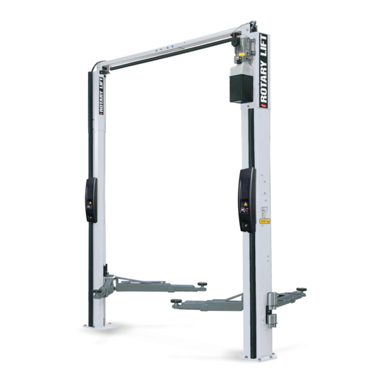
600 Series
Two Post Surface Mounted Lifts
SPOA3T Series Capacity:
3000 kg (6600 lbs.)
750 kg (1650 lbs.) per arm
LP20324
I
I
N
N
S
S
T
T
A
A
L
L
L
L
TUV
A
A
Rheinland
T
T
I
I
O
O
N
N
I
I
N
N
S
S
T
T
R
R
U
U
C
C
T
T
I
I
O
O
N
N
S
S
IN20396
Rev. A 6/21/2005
Advertisement

Related Manuals for Rotary SPOA3TE 600 Series


Summary of Contents for Rotary SPOA3TE 600 Series
- Page 1 SPOA3TE 600 Series Two Post Surface Mounted Lifts SPOA3T Series Capacity: 3000 kg (6600 lbs.) Rheinland 750 kg (1650 lbs.) per arm LP20324 IN20396 © June. 2005 by Rotary Lift. All rights reserved. CO6241.12 Rev. A 6/21/2005...
- Page 2 Fig. 1 Bay Layout Table A 10'-3" (3121mm) Outside baseplate to baseplate. B 2'-5" (737mm) C 1'-9-1/2" (547mm) D 8'-5" (2560mm) Between columns. E 9'-0" (2743mm) Minimum to nearest obstruction. F 15'-0" (4572mm) Minimum to nearest obstruction. G 7'-8-1/8" (2340mm) Inside baseplate to baseplate. H 11'-9"...
- Page 3 1. Lift Location: 5. Concrete and Anchoring (Anchors Not Provided): Use architects plan when available to locate lift. Fig. 1 shows dimensions of a typical bay layout. Note: Recommended anchors - Hilti HSA-A stud anchor 2. Lift Height: 20mm dia. x 170mm Lg. or equal. See Fig.
- Page 4 6. IMPORTANT Using the horse shoe shims provided, shim each column base until each column is plumb, Fig. 5a. If one column has to be elevated to match the plane of the other column, full size base shim plates should be used (Reference Shim Kit). Recheck columns for plumb.
- Page 5 7. Overhead Assembly: Assemble overhead, Fig 6. Adjust to dimension, shown. Install (4) M10 x 20Lg. HHCS and Flanged lock nuts, (2) Each Side. DO NOT TIGHTEN. (4) M10 x 20Lg. HHCS Fig. 6 8'-9-1/2" (2676mm) 8. Overhead Switch Installation: Mount switch assembly towards power unit column using (2) M6 x 20 lg.
-
Page 6: Power Unit
Install power unit onto column extension, Fig. 11. Slide bolt/nut 10. Overhead: With a ladder by each column, two people position the overhead combination into top set of holes and down to bottom of slot. Install assembly onto column mounting brackets and fasten with (2) M10 x HHCS, Vibration Pad, and Flanged HHCS in bottom power unit holes 20mm HHCS and (2) M10 lock nuts, Fig. - Page 7 12. Installing Locking Latches: A) Install locking latches, lock hole covers, (1 hose clamp each A (2 each column) M6 x 1.0 x 12Lg. carriage bolt side) and lower column hole plugs onto columns, Fig. 13. B (2 each column) M6 x 1.0 lock nut C (3 each column) M10 x 1.5 x 20Lg.
-
Page 8: Oil Filling
13. Installing Upper Enclosure Mounting Studs: 16. Flared Fittings Tightening Procedure: Flared Fittings Tightening Procedure A) Install (6) M6 x 12 carriage bolts and mounting studs, Fig. 1. Screw the fittings together finger tight. Then, using the proper size 14. Mounting studs protrude outward from column. wrench, rotate the fitting 2-1/2 hex flats. - Page 9 HOSE DETAIL M10 x 1.5 x 20Lg. carriage bolt Hose clamp M10 lock nut M10 x 1.5 x 20Lg. HHCS Overhead hose Fig. 15 Power unit hose Fill breather cap Review step 15 Fig. 15a...
- Page 10 18. Installing Lower Enclosure Mounting Studs, (Adapter Holders, and Tool Holders Optional): A) Install lower enclosure mounting studs, (adapter holders and tool holders optional), Fig. 16 B) (Install adapters optional), Fig. 16. Fig. 16 Fig. 16 Detail Power unit column M6 x 1.0 x 16mm carriage bolt M6 x 1.0 lock nut Tool holder (Optional)
- Page 11 C) Push cable 1 up until the stud is out of the carriage top opening. 19. Equalizing Cables: A) Slightly raise each carriage assembly and depress the locking latch D) Run a nylon insert locknut onto cable 1 stud so 13mm of the stud assembly and lower carriages to lowest latch postion, Fig.
- Page 12 NOTES: Unit not suitable for use in unusual conditions. Contact Rotary Lift for moisture and dust environment duty unit. MOTOR OPERATING DATA - SINGLE PHASE (*F MODELS) LINE VOLTAGE POWER...
- Page 13 3 Phase Installation Fig. 21 Detail Fig. 21 Facility power cable. Back side of disconnect. Grounding screw attached to back plate. Power Unit Area Slave Enclosure Latch2 Motor Overhead Overhead Motor Relay Coil Coil Latch1 Latch1 Fig. 21a NP812 Master Enclosure REV.
- Page 14 21. Electrical Continued: A) Wire overhead switch, Fig. 21a and Fig.23. B) Route overhead cable along hydraulic hose and plug into harness on back plate of master control panel. C) Attach plug from harness of master control panel into the master side lock solenoid.
- Page 15 Fig. 23 Fig. 23 Detail Wire overhead switch Attach plug end of overhead switch cable into harness located on master control back plate. Attach plug from harness of master control panel into the master side lock solenoid. Attach 6 position plug on slave solenoid cable to 6 position plug on master side wiring harness.
- Page 16 22. Installing The Master Control Cover: D) Enclosures will attache to column with Attach the switch contactors from harness on back plated of master M6 x 1.0 x 10Lg. flanged BHCS and rubber washers, Fig. 25. control to the master control cover. Tabs that lock switch contactors into E) Slave cover attaches to column with (3) M6 x 1.0 x 10Lg.
- Page 17 Fig. 25 Detail Cut to fit gaskets and install them on the master and slave covers. Wire tie all hoses and cables together making sure that there are not kinks or crimps in the cables and hoses. NOTE: Transparent hose guard should be placed at top of enclosure to prevent hose chafing.
-
Page 18: Initial Start-Up
24. Initial Start Up: CAUTION Turn disconnect to ON position from the master control panel, Fig. 26. NOTE: For further operation instructions refer to the operation and maintenance guide included with this literature package. ® LOWER TO LOCKS Fig. 26 ®... - Page 19 Fig. 29a Fig. 28 Fig. 29a Front Arm Guard Detail (2) Straps Fig. 28 Detail (2) Arm guard assemblies TOP will be marked on top side of restraint (4) 1/4-20NC Hex FLgd Wzlock nuts Pltd gear. Note beveled orientation (3) Each arm - 3/8"-16NC x 1-1/2" HHCS (3) Each arm - 3/8"...
- Page 20 27. Door Bumper Installation: Install door bumpers and finger guards, Fig. 30. 28. Wheel Spotting Dish: Position wheel spotting dish, for appropriate lift model, as illustrated in Fig. 1. Drill (2) 3/8" holes 2-1/2" deep in concrete floor using holes in wheel spotting dish as guide.
- Page 21 30. Oil Bleeding: Press on touch pad and raise lift about 609mm Open cylinder bleeders approximately, 2 turns. Close bleeders when fluid streams. Press on the touch pad to fully lower lift. Fill tank until it reaches the MIN______ mark on the tank. System capacity is (18) liters. Replace fill-breather cap.
- Page 22 NOTES...
- Page 23 NOTES...
- Page 24 Thank You Trained Operators and Regular Maintenance Ensures Satisfactory Performance of Your Rotary Lift. Contact Your Nearest Authorized Rotary Parts Distributor for Genuine Rotary Replacement Parts. See Literature Package for Parts Breakdown. European World Wide Contact Information Headquarter World Headquarters/USA: 1.812.273.1622...
Need help?
Do you have a question about the SPOA3TE 600 Series and is the answer not in the manual?
Questions and answers