Table of Contents
Advertisement
Quick Links
Advertisement
Table of Contents

Related Manuals for mru MONTEC


Summary of Contents for mru MONTEC
- Page 1 1 Table of contents MONTEC MANUAL 7202EN...
- Page 2 Email: info@mru.de Homepage: www.mru.eu MRU GmbH is not liable for damage or injury resulting from the incorrect interpretation of information in this manual or from the incorrect use of this manual. FOR MORE INFORMATIONS ABOUT COMPANY MRU PLEASE VISIT OUR WEBSITE...
- Page 3 1 Table of contents Legal information / Copyright notice Original operating instructions © 2024 by MRU All rights reserved No part of this work may be reproduced in any form (print, photocopy, electronic media or any other process) or processed,...
-
Page 4: Table Of Contents
General important information for the operator of the measuring device MRU warranty conditions Disposal take-back guarantee Return of devices Packaging 2.10 Taking back parts containing harmful substances 2.11 The company MRU GmbH Notes on device and safety Qualification Instructions on the safe operation of the device 3.2.1 Visual inspection 3.2.2... - Page 5 Carrying out tests with (optional) wireless accessories 7.2.1 Wireless temperature measuring clamps 7.2.2 Operating the wireless temperature measuring clamps with the digital manifold gauge Maintenance of the MRU measuring device Maintenance Cleaning the valve block Technical data General technical data digital manifold gauge Measured values...
- Page 6 1 Table of contents Customer service, service centres...
-
Page 7: Introduction And Basic Conditions
2.2 General information on the manual • This manual will enable you to understand and safely operate this MRU analyser. • Please read this manual carefully. • Familiarise yourself with the product before using it. -
Page 8: Safety Signs
2 Introduction and basic conditions 2.3 Safety signs These safety instructions are used in this manual DANGER Refers to an imminent danger that will lead to serious physical injury or death if ignored. WARNING Indicates an imminent danger which, if ignored, can lead to serious physical injury, damage to property or death CAUTION Indicates a potentially hazardous situation which, if not avoided,... - Page 9 2 Introduction and basic conditions Mandatory Figure Meaning symbol number M002 Observe the operating instructions M004 Use eye protection M008 Use foot protection M009 Use hand protection...
-
Page 10: General Important Information For The Operator Of The Measuring Device
Hazards must be identified and suitable countermeasures taken as part of a risk assessment. When using the MRU measuring devices to measure other devices or systems, the manufacturer’s documentation of the system or device manufacturer must be observed. -
Page 11: Mru Warranty Conditions
The return delivery must be free of charge for us. Parts containing hazardous substances are: e.g. electrochemical sensors. 2.8 Return of devices MRU GmbH is obliged to take back all analysers delivered after 13 August 2005 for proper disposal. The device must be returned to MRU with postage prepaid. -
Page 12: The Company Mru Gmbh
2.11 The company MRU GmbH From left to right: Production - Sales, administration and development - Customer service The measuring device is manufactured by MRU GmbH in Neckarsulm-Obereisesheim, a medium-sized company that has specialised in the development, production and sale of high-quality emission analysis systems since 1984. -
Page 13: Notes On Device And Safety
They are informed about all the risks involved in their work, are able to recognise risks themselves when carrying out their work and have a suitable switching authorisation. You can contact the MRU service for repairs, calibrations, retrofitting and disposal issues. Qualification Instructed... -
Page 14: Instructions On The Safe Operation Of The Device
➢ Only use original spare parts. ➢ Only operate the device with the power supply unit supplied. ➢ Do not store the device together with solvents, acids or other aggressive substances. 3.3 Data security MRU uses internationally available standard transmission systems for data transfer. -
Page 15: Intended Use
Any other use deviating from this is not permitted. Any other use is not in accordance with the intended use. MRU is not liable for this. Any guarantee or warranty is void. Non-compliance with the operating instructions is not in accordance with the intended use. -
Page 16: Environmental Protection
Dispose of the digital manifold gauge in accordance with the regulations applicable at the place of disposal or send it back to MRU return postage prepaid. -
Page 17: Description Of The Device
4 Description of the device 4 Description of the device 4.1 Rating plate The respective configuration of your device can be read off the rating plate. Rating plate Description Serial number Model Voltage supply IP protection Radio frequency Wireless certification ID Labels... -
Page 18: Commissioning
5 Commissioning 5 Commissioning REREQUISITE CAUTION Falling down of the digital manifold gauge The result can be bruising of the foot ➢ Wear safety boots ➢ Use the hook (Figure 1/10) to attach the digital manifold M008 gauge. ➢ Do not hold devices, especially when they are connected to a system, in your hand and secure the devices against falling down. -
Page 19: Unpacking The Device
5 Commissioning 5.1 Unpacking the device CAUTION Weight of the device Impact and crushing injuries ➢ Always put the device down safely. ➢ Unpack the device in a location where you are M008 undisturbed. ➢ Observe the weight and the dimensions of the device; in case of doubt, lift the device with two persons or use a lifting device. -
Page 20: Operation
6 Operation 6 Operation 6.1 Overview digital manifold gauge Montec front Montec back... - Page 21 6 Operation Description Display Mouldings allow the digital manifold gauge to be securely gripped by hand Screw-in socket with screwed-on protection caps ℹ The protection caps protect the screw-in sockets against mechanical damage and contamination. Be sure not to lose the protection caps! Inspection glass Keypad ℹ...
-
Page 22: Connections Digital Manifold Gauge
6 Operation 6.2 Connections digital manifold gauge Connections Montec valve block Connections Montec back... -
Page 23: Shut-Off Valves
6 Operation Description Connection low pressure Connection test gas or refrigerant Connection vacuum pump Connection high-pressure side Screw-in socket to screw down unused connecting hoses Drilled hole for theft protection Earth connection USB-C connection Type K socket (thermocouple socket) high temperature Type K socket (thermocouple socket) low temperature Ambient temperature sensor Fold-out hook to attach the digital manifold gauge at a... - Page 24 6 Operation • The front left shut-off valve opens or closes the connection to the gas cylinder with refrigerant or test gas.
- Page 25 6 Operation CAUTION Pressure or vacuum in the valve block Stress and premature wear of the gaskets between valve block and shut-off valve can be the result. ➢ Ensure that after the completion of work, there is no pressure or vacuum in the valve block between the shut-off valves.
-
Page 26: Valve Block
6 Operation 6.2.2 Valve block Figure 4: Valve block – schematic representation Description Connection low-pressure side Connection high-pressure side Connection refrigerant/test gas Connection vacuum generation Pressure sensor low-pressure side Vacuum sensor Pressure sensor high-pressure side Shut-off valve low-pressure side Shut-off valve high-pressure side 10 Shut-off valve refrigerant/test gas 11 Shut-off valve vacuum generation The schematic diagram is also displayed in the menu Device... -
Page 27: Control Elements Of The Digital Manifold Gauge Display
6 Operation 6.3 Control elements of the digital manifold gauge display Keypad Description Function key F1 multiple assignment Function key F2 multiple assignment Switch digital manifold gauge on and off Calling the Home menu Direction keys up, down, left, right - to navigate the menus... -
Page 28: Switching The Digital Manifold Gauge On And Off
6 Operation 6.4 Switching the digital manifold gauge on and off 6.4.1 Switching on ▶ Press the ON/OFF to switch on the digital manifold gauge. ✔ You will see the Home menu, the device is switched on. 6.4.2 Switching off ▶... - Page 29 6 Operation...
-
Page 30: Display Of The Digital Manifold Gauge
6 Operation 6.5 Display of the digital manifold gauge This chapter describes the menu navigation that is shown on the display of the digital manifold gauge. ℹ Navigate or change the displayed values with the arrow keys up, down, right and left. Confirm your selection or select the next submenu with the function key F2 depending on the instructions in the... - Page 31 6 Operation Designation Menu bar Rolling up/down State of charge of digital manifold gauge battery Field with multiple assignments: • In submenus return • Zeroing P=0 Field with multiple assignments: • Selection OK • Measurements Start Subitems of the Home menu Variable field...
-
Page 32: Superheat/Subcooling
6 Operation 6.5.2 Superheat/Subcooling Under the menu item Superheat/Subcooling you will find the measured values of the sensors you have connected, a possibility for zeroing and for selecting the refrigerant. ▶ Select the menu item Superheat/Subcooling in the Home menu. Superheat/Subcooling menu Designation Superheat / Subcooling menu... - Page 33 6 Operation To achieve a meaningful measuring result it is crucial to take into account the local conditions. This can only be ensured by zeroing before every measurement. The pressure in the system can for instance be influenced by factors such as solar radiation and temperature change in the measuring range.
- Page 34 ✔ You reach the Home menu. CAUTION Pressure sensor defective Hence, the measurement is not reliable ➢ Put the digital manifold gauge out of operation if the pressure sensor does not display anything. Have the digital manifold gauge examined by your MRU Service Center.
-
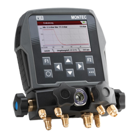
Page 35: Evacuation
6 Operation 6.5.3 Evacuation Under the menu item Evacuation you find settings regarding the evacuation measurement of your system. The vacuum sensor of the digital manifold gauge is used for that purpose. ▶ Select the menu item Evacuation in the Home menu. Here you can specify the following values for the vacuum retention test: •... - Page 36 6 Operation Evacuation menu Description Evacuation menu ✔ Y axis (pressure) Measured ambient air temperature return to setting the evacuation target and maximum vacuum ▶ Press You are taken to the menu where you can set the evacuation target and the maximum vacuum stop the measurement X axis in sec Set evacuation target...
- Page 37 6 Operation Pressure gradient: Pressure value outside the measuring range of the vacuum sensor Description The pressure gradient ∆P specifies an orientation value by how many mbar per second the pressure drops or rises. Here the pressure ∆P drops by -17.4 mbar/s. The pressure gradient is calculated from one of the two pressure sensors (high pressure/low pressure sensor).
-
Page 38: Leak Test
6 Operation 6.5.4 Leak test Under the menu item Leak test you find the graphical representation of the pressure gradient of the connected measuring instruments over time. ▶ In the Home menu, select the menu item Leak test. Menu leak test Description Leak test Y axis (pressure) - Page 39 6 Operation ▶ You are asked whether you really would like to carry out zeroing after you have pressed ▶ You are asked “Carry out zeroing?”. Use the arrow keys up and down to select “No”. ✔ You did not carry out zeroing. Start / Stop of measurement ▶...
-
Page 40: Refrigerant Info
6 Operation 6.5.5 Refrigerant info Under the menu item Refrigerant info you obtain information on the refrigerant you would like to work with. ▶ Select the menu item Refrigerant info. Display Refrigerant info ▶ Use up and down to navigate between the setting options 1 to 4. - Page 41 The values under Refrigerant information serve as guidelines. Despite thorough research, we can accept no liability for the correctness of all values. MRU in particular assumes no liability for any damage or consequences arising from the use of the refrigerant...
-
Page 42: Settings
6 Operation 6.5.6 Settings Under the menu item Settings you find the device settings, such as language and display brightness, resetting to default settings and many other customisable applications. In the Home menu, select the menu item Settings. Settings menu, first display Settings menu rolled down, further setting options... - Page 43 6 Operation Description Settings menu Display: Configure the display settings according to your requirements. ▶ Select Display to set the following in the submenu with left and right: • LCD brightness (in % from 20 -100) • LCD dimming (from 0 min (Off) to 20 min) ℹ...
- Page 44 6 Operation ✔ You have switched the keyboard beep on or off. Wireless sensors: Turn the submenu Wireless in the Home menu ON or OFF. ▶ Use left and right to turn the submenu Wireless ON or OFF. ✔ You have turned the submenu Wireless in the Home menu ON or OFF.
- Page 45 6 Operation • Serial number Return to the Settings menu: ▶ Select return to return to the Settings menu. ✔ You have returned to the Settings menu. Return ▶ Press ✔ You reach the Home menu. Selection OK CAUTION The digital manifold gauge moves in an unpredictable manner as refrigerant flows through it at high pressure.
- Page 46 6 Operation ➢ Check the sound condition of the connection hoses. ➢ Ensure that the connection hoses have been correctly screwed in and tightened hand-tight. Only start work once you have done so. CAUTION Gasket in the shut-off valve or hose connection damaged This can result in leaks at the shut-off valve or hose connection.
- Page 47 6 Operation...
-
Page 48: Hoses
6 Operation 6.6 Hoses The digital manifold gauge comes with four hoses. These are exclusively intended for use within the scope of the technical data of the digital manifold gauge. Hoses Description Straight screwed connection - recommended connection of the hose with the digital manifold gauge Angled screwed connection –... -
Page 49: Long-Term Measurement
6 Operation Hose marked in blue; recommended application: Low pressure Hose marked in red; recommended application: High pressure Hose marked in yellow; recommended application: Test gas/refrigerant 6.7 Long-term measurement When you carry out a long-term measurement, you can dim and switch off the display to save electricity. -
Page 50: Initial Filling Of Heat Pumps And Refrigeration Systems
6 Operation 6.8 Initial filling of heat pumps and refrigeration systems Your safety takes top priority when you commission systems or carry out maintenance. WARNING Refrigerant escaping from leaking systems Personal injuries and environmental damage can be the result. ➢ Carry out a leak test before filling a system. CAUTION Uncontrollably whipping hoses Pressure can cause the hose to whip uncontrollably when it is... -
Page 51: Pressurising The System With Test Gas
6 Operation 6.8.1 Pressurising the system with test gas ℹ The most common test gas for leak tests on heat pumps or refrigeration systems is nitrogen or forming gas. Leak test; connection digital manifold gauge, system and test gas Description Heat pump/refrigeration system Test gas cylinder Shut-off valve low-pressure side... - Page 52 6 Operation REREQUISITE ☑ Make sure that the test gas cylinder is closed. ☑ The digital manifold gauge is switched off, all the shut-off valves are closed. ☑ You have connected all connections as specified in the figure above. Connect the high-pressure side of the heat pump or refrigeration system with the high-pressure side of the digital manifold gauge and also connect the low-pressure sides with each other and the test gas cylinder with the screwed...
-
Page 53: Carrying Out Evacuation And Leak Test
6 Operation rubber gaskets. Replace any damaged gaskets and check the system leak tightness again. 6.8.2 Carrying out evacuation and leak test Evacuating the system; connection digital manifold gauge, system and vacuum pump Description Refrigeration system or heat pump Vacuum pump Shut-off valve low-pressure side Shut-off valve vacuum pump Shut-off valve high-pressure side... - Page 54 6 Operation REREQUISITE ☑ The vacuum pump is off. ☑ The digital manifold gauge is switched off, all the shut-off valves are closed. ☑ You have connected all connections as specified in the figure above. Connect the high-pressure side of the heat pump or refrigeration system with the high-pressure side of the digital manifold gauge, and the low-pressure sides with each other and connect the vacuum pump with the screwed connection...
-
Page 55: Filling In Refrigerant
6 Operation rubber gaskets. Replace any damaged gaskets and check the system leak tightness again. 6.8.3 Filling in refrigerant NOTE Refrigerant at the vacuum sensor can falsify the measurement as the refrigerant has a lower thermal conductivity than air or nitrogen. - Page 56 6 Operation Shut-off valve high-pressure side Connection low-pressure side Connection test gas Connection high-pressure side REREQUISITE ☑ Ensure that the refrigerant cylinder is closed. ☑ The digital manifold gauge is switched off, all the shut-off valves are closed. ☑ You have connected all connections as specified in the figure above.
- Page 57 6 Operation...
-
Page 58: Temperature Measurement
6 Operation 6.9 Temperature measurement 6.9.1 Wired temperature measuring clamps When checking a system’s function and measuring the subcooling and superheat values, you can use the wired temperature clamps. Connection temperature clamp to type K socket Description Digital manifold gauge Type K socket low temperature range Type K socket high temperature range Temperature clamps... - Page 59 6 Operation ✔ The measuring result is shown on the display of the digital manifold gauge. ℹ Pay attention that the time of the setting Automatic off after [h] is greater than the expected time of your long-term measurement and the set time of the setting LCD off after [h] to avoid you interrupting your measurement inadvertently.
-
Page 60: Options
7 Options 7 Options 7.1 Accessories The optional accessory parts described in this section can be supplied with the digital manifold gauge. Digital manifold gauge with options... - Page 61 Charging the digital supply unit manifold gauge Wired temperature clamps Temperature measurements at heat pumps or refrigeration systems Charging cable Montec Charging cable of the power supply unit digital manifold gauge is located underneath the digital manifold gauge, not illustrated...
-
Page 62: Carrying Out Tests With (Optional) Wireless Accessories
7 Options 7.2 Carrying out tests with (optional) wireless accessories 7.2.1 Wireless temperature measuring clamps When you check the function of a system, you can use the wireless temperature clamps. Wireless temperature measuring clamp Description View bottom side left View upper side left View with open clamp bottom right hand side The LED blinks blue when the temperature measuring clamp is switched on and sends data. - Page 63 7 Options Clamp handle Temperature sensor Recess to open the battery compartment Battery compartment for 2x AA batteries Rating plate Commissioning the wireless temperature measuring clamps: ▶ Open the battery compartment. ▶ Insert the batteries. ▶ Press On for 1 sec. ℹ...
-
Page 64: Operating The Wireless Temperature Measuring Clamps With The Digital Manifold Gauge
Wireless sensors are supported from software version 1.00.00. If your digital manifold gauge still runs on an earlier version, please contact your MRU Service Centre. To activate the wireless sensor settings: ▶ Select Settings from the Home menu. ▶ Use the arrow keys left and right to set the wireless sensors to ON. - Page 65 7 Options ▶ Return to the Home menu. Managing wireless sensors: ▶ Select Wireless sensors from the Home menu. Home menu - wireless sensors Description Home menu Submenu Wireless sensors The menu is only displayed if the wireless sensors are set to ON in the submenu Settings.
- Page 66 7 Options Working with the wireless temperature measuring clamps: Menu wireless sensors Description Menu Wireless sensors First sensor in the list of wireless sensors Second sensor in the list of wireless sensors Third sensor in the list of wireless sensors Select / deselect the sensor (hook / unhook) Selected and deselected sensors Name of sensor...
- Page 67 7 Options ▶ Switch on the sensor. NOTE Always ensure that you check the charge state of your batteries before you start a measurement. ▶ Select the desired sensor with the arrow keys down and up Press Select. ▶ Change to the menu Cold/Heat via the Home menu. ✔...
- Page 68 7 Options The measured value of the wired temperature measuring clamps is always shown on the side where the wired temperature measuring clamp is plugged into the type K socket. Measured value of the wireless temperature measuring clamps The display position is variable. Selection of display position Select the display position with the arrow keys left and right...
-
Page 69: Maintenance Of The Mru Measuring Device
8 Maintenance of the MRU measuring device 8 Maintenance of the MRU measuring device 8.1 Maintenance Maintenance point Activity Interval Valves Check valves for leak Before every assignment tightness, have leaking valves replaced at your MRU Service Centre. Connecting hoses... -
Page 70: Cleaning The Valve Block
Repeat the steps as required at least three times or until the contaminations have been removed. ℹ If an incorrect refrigerant has been used, for instance ammonia (NH3), have the digital manifold gauge checked by your MRU Service Centre. ✔ You have cleaned the digital manifold gauge. -
Page 71: Technical Data
9 Technical data 9 Technical data 9.1 General technical data digital manifold gauge Specification Value Operating temperature -20°C ... +50°C Storage temperature -20°C ... +50°C / -4°F ... 122°F Li-Ion, >20h (brightness 100%) Internal rechargeable battery, operating time >40h (brightness 50%) >150h (display off) Rel. -
Page 72: Measured Values
9 Technical data 9.2 Measured values Temperature measurement T1, T2 Number of thermocouple type K inputs Measuring range -40 °C .. 999°C Accuracy abs. / of measured values ±1°C / 0.50% Pressure Details on measurement accuracy Number of pressure sensors Measuring range -1...50 bar Overload... -
Page 73: Temperature Clamp Wdt
9 Technical data 9.4 Temperature clamp WDT Specification Value Operating temperature -20°C ... +45°C Storage temperature -20°C ... +50°C / -4°F ... 122°F Weight 0.1 kg Width: 22 mm, Dimensions Height: 120 mm Depth: 70 mm Material PA6GF30 Sensor type Type K thermocouple Measuring range -40°C ... -
Page 74: Indications Or Malfunctions
Device switches off The battery is empty. Recharge the battery. automatically. If the battery discharges too fast, have the battery replaced at your local MRU Service Centre. The device cannot be The battery is empty. Recharge the battery. switched on. -
Page 75: Decommissioning
ℹ Information on the disposal of your device can be obtained from your MRU Service Centre. Parts containing hazardous substances, such as electrochemical sensors, batteries or rechargeable batteries can be sent back to MRU. The return shipment must be free of charge for MRU. -
Page 76: Declaration Of Conformity
12 Declaration of Conformity 12 Declaration of Conformity... -
Page 77: Photo Credits
13 Photo credits 13 Photo credits M002: Von ISO - ISO 7010 - M002Eigenes Werk, CC BY-SA 3.0, https://commons.wikimedia.org/w/index.php?curid=27519901 M004: Von ISO - ISO 7010 M004Eigenes Werk, Gemeinfrei, https://commons.wikimedia.org/w/index.php?curid=26466677 M008: Von ISO - ISO 7010 M008Eigenes Werk, Gemeinfrei, https://commons.wikimedia.org/w/index.php?curid=26466756 By ISO - ISO 7010 - M009Own work, Public Domain, https://commons.wikimedia.org/w/index.php?curid=26466778 W071: Von Clemenspool –... - Page 78 MRU customer service can be contacted by telephone, fax and email: Tel.: +49 (0) 7132 - 99 62 61 Fax: +49 (0) 7132 - 99 62 60 service@mru.de To find your nearest MRU service centre for your MRU products, please visit our website: https://www.mru.eu/service/regionale-servicestellen/...
Need help?
Do you have a question about the MONTEC and is the answer not in the manual?
Questions and answers