mru MGAprime User Manual
Hide thumbs
Also See for MGAprime:
- User manual (126 pages) ,
- User manual (8 pages) ,
- User manual (123 pages)
Table of Contents
Advertisement
Quick Links
Advertisement
Table of Contents

Related Manuals for mru MGAprime


Summary of Contents for mru MGAprime
- Page 1 USER MANUAL prime 9452EN-PR...
- Page 2 Legal notices / Intellectual property rights comments Original user manual © 2018 by MRU No part of this manual my be published in any form (print, photocopy, electronic media or any other publication form) without a written approval by the publisher.
-
Page 3: Table Of Contents
Content 1 Introduction ..........................5 Intended use ............................5 About us ...............................6 2 Information for product and safety ..................7 Safety manual ............................7 Safety precautions ..........................7 3 Description ........................... 8 Task ................................8 Gas flow diagram ..........................8 The measuring instrument ......................9 Connectors ............................10 Probes .............................. - Page 4 8 Data memory..........................24 Organization of the Data memory ..................24 Information about the data memory ..................24 Site administration ........................24 Data transfer via USB (CSV export) ..................26 Export of measurements ......................26 9 Extras ............................27 Access key ............................27 Internal Log Settings ........................
-
Page 5: Introduction
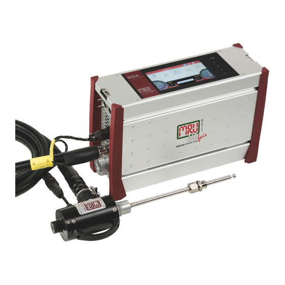
Please ensure to hand over all documents to when handing the analyz- er over to others. Intended use The Analyzer MGAprime is designed for the gas analysis of flue gases, as they are emitted from gas/oil burners, engines, or heating and power appliances. -
Page 6: About Us
Introduction About us The Analyzer is produced by the MRU GmbH in Neckarsulm, Germany (founded in 1984), a medium sized company that specializes in develop- ing, producing and marketing high quality emission monitoring analyz- ers. MRU GmbH produces a wide range of instruments, from standard analyzers up to tailor made industrial analyzers. -
Page 7: Information For Product And Safety
Information for product and safety Information for product and safety Safety manual All general information and safety precautions of MRU products are listed in the supplied separate safety manual. Therefore this manual must be read and observed before the first use of the instrument. -
Page 8: Description
Description Description Task The instrument is designed for the gas analysis of flue gases, as they are emitted from gas/oil burners, engines, or heating and power appliances. The instrument is intended to support the user in control and indicative measurements in an efficient, accurate and reliable way The instrument provides a full set of all equipment and sensors required for a emission control measurement: y heated probe incl heated filter... -
Page 9: The Measuring Instrument
Description Fresh air inlet Sample gas inlet Condensate outlet Diff. Pressure connector Vent collection box Vent outlet Sample gas filter (PTFE) Dust filter Auto-zero solenoid valve Sample gas pump Double stage gas cooler Sample flow sensor Oxygen sensor Vent pump O2-ECS or O2 paramagnetic Infrared (NDIR) bank 10 Acrodisc PTFE filter... -
Page 10: Connectors
Description Connectors Loudspeaker Ethernet (LAN) USB socket Second USB socket (Option) RS485 (Option) Analog outputs 4 ... 20 mA Mains power supply Sample gas filter Condensate outlet port Sample gas outlet port (VENT) Hose connection DN 4/6 Hose connection DN 4/6 Fresh air inlet port Sample gas inlet port Outlet fan of gas cooler... -
Page 11: Gas Sampling Probe "Tr
Description Gas sampling probe “TR” Heated probe with heated and exchangeable glass filter. The probe tube includes a gas temperature sensor and is available in different tube lenghts. Probe handle Probe tube Fast locking coupling Probe cone Cable plug (14-pin) Heated hose line Cable coupler (5-pin) Fast locking coupling... -
Page 12: Ir Measurement
Description IR measurement The instruments NDIR gas sensor is able to detect up to 8 different gases. It is most advanced in terms of its long-term stability due to a dedicated stabilization technology including a permanent zeroing by operating the bench at two different gas pressure values. -
Page 13: Operation
Operation Operation Commissioning The instrument is delivered as a complete assembly ready for use. f Check the instrument regarding condition and integrity after delivery. f Connect the instrument to the power grid. Ö The instrument switches on and start the operating system. Ö... -
Page 14: Operating Panel
Operation Operating panel All functions are controlled via the touch surface of the instrument. Dif- ferent gestures are available in the individual menus and windows. Power-on and reset Reserve Reserve LED display mains operation/battery charging mode Reserve Current flow rate Current temperatures heated hose Selected measuring program, e.g. -
Page 15: Settings
Settings Settings After the analyzer has been inspected and is ready for start-up it can be switched on and personalized settings can be entered. These settings can be changed at any time. Analyzer settings After the analyzer has been inspected and is ready for start-up it can be switched on and personalized settings can be entered. -
Page 16: Setting Time And Date
Settings Negative gas on/off Negative gas readings Caused by tem- readings perature drift of a sensor are suppressed (shown as zero) or displayed on/off VNC Viewer for remote control via LAN Reference tem- Calculation of the values for a standard perature state at reference temperature Interval... - Page 17 Settings The measurement window for gas analysis can be configured and adapt- ed to your needs. The measuring window initially displays 12 measured values, by a scrolling gesture it will display more values. Moving a value field f Touch and hold the value field. Ö...
-
Page 18: Gas Flow Measurement
Settings Gas flow measurement Set up measurement window With the flow measurement option are further measurements available: y v-flow y Flow rate y Mass flow carbon Parameter for gas flow measurement f Choose the right context button - menu item “gas flow measurement”. MGA prime 18 / 44 Version 1... -
Page 19: Measurement
Measurement Measurement Preparation of each measurement 6.1.1 Power supply The analyzer can be operated with an internal battery to warm up the instrument or to use internal instrument functions. A mains connection is required for the measurement including heated gas sampling probe and heating hose. -
Page 20: Operating Temperature
Measurement f The flow rate of the gas should be within the specified range. Other- wise, please check probe and filter for clogging f Temperatures of NDIR and heating hose should be within the specified range in order to guarantee a sufficient measuring accuracy. In the Extras menu under “Connections”... -
Page 21: Instrument Leak Test
Measurement y Heating the probe and the heating hose y Warm up the NDIR bench (if available) y After the operating temperatures have been reached, the gas pump is switched on and the analyzer takes the zero point with fresh air. y After the zeroing, the analyzer is ready for operation If a new zero point is required by further heating the instrument, it can be started via the context menu. -
Page 22: Store The Measurement Results
Measurement 6.2.2 Store the measurement results The measured values can be stored in a site via the context menu / Store menu entry. The measurement itself continues until switch off of the analyzer. Continuous data logging A continuous measurement logging is possible via the context menu / “Start logging”. -
Page 23: Maintenance And Cleaning
Check the round filter at the front of the instrument and replace if necessary. Maintenance An annual service check and if necessary adjustment of the sensors at an MRU service department (www.mru.eu) are recommended for the pres- ervation of value. MGA prime Version 1... -
Page 24: Data Memory
Data memory Data memory Organization of the Data memory Basis of the data memory of the analyzer is a set of sites stored in the instrument. Every site exists of a unique site number and 12 freely usable text lines which can have, e.g., the address, customer name etc. The instrument can store up to 1.000 different sites. - Page 25 Data memory y Changes in the site description may be entered and stored y A site may be deleted by the “delete” button. y Measurements assigned to the selected site are displayed when the “Measurement” button is activated. In the menu Measure you can see stored measurements MGA prime Version 1 25 / 44...
-
Page 26: Data Transfer Via Usb (Csv Export)
Data memory Data transfer via USB (CSV export) The data exchange format is CSV. A character-separated values (CSV) file is a simple text format for a database table. Each record in the table is one line of the text file. Each field value of a record is separated from the next by a character. -
Page 27: Extras
Extras Extras IIn the Extras menu, the time / date setting (chapter 5.2) and the connec- tion possibilities of the instrument (chapter 3.4) are further menu items for service purposes available. The first menu items have already been explained during “settings”. Access key The entry of an access key (password) is for maintenance action and allows experienced users to operate on the operating system level. -
Page 28: Service Values
This screen displays a number of internal parameters and their values. In case of unexpected behavior of the instrument it might be helpful to communicate those values to our worldwide service staff: www.mru.eu Analog output setup (4 – 20 mA) There are 8 analog outputs available (4-20 mA). -
Page 29: Setting Of Lower Limit (4 Ma)
Extras 9.4.1 Setting of lower limit (4 mA): This setting determines the lower end value, corresponding to 4 mA. If the measured value falls below the set value, the analog output stops at 4 mA. 9.4.2 Setting of upper limit (20 mA): This setting determines the upper end value, corresponding to 20 mA. -
Page 30: Pin Assignment Of The 4-20 Ma Interface
Extras 9.4.4 Pin assignment of the 4-20 mA interface Info In the Info menu, version information and installed options can be viewed. Options MGA prime 30 / 44 Version 1... -
Page 31: Information On The Instrument Components
Information on the instrument components 10 Information on the instrument components Especially for service or inquiry This menu can be selected from the main menu with the adjacent but- ton. In addition to special instrument information and the possibility of instru- ment matching for service stations, a firmware update is also possible. -
Page 32: Specifications
Specifications 11 Specifications 11.1 NDIR measured values Range Resolution Accuracy 1 ppm 250 - 4000 ppm 1 ppm 200 - 1000 ppm 1 ppm 200 - 4000 ppm Repeatability: 1% v.MB. 40 Vol% 0,01 Vol% (CH4: 2% v. MB) 8h-Drift: 1% v.MB. 200 - 10000 ppm 1 ppm Linearity: 2% v. -
Page 33: Gas Sampling And Conditioning
Specifications 11.4 Gas sampling and conditioning 11.4.1 Electrochemical-, temperature- and pressure sensors Electrochemical sensor Long Life Measuring range 0 - 25 Vol% Resolution 0,01 Vol% Abs. accuracy ± 0,2 Vol% Response time T90 < 20s Years expected lifetime (@air) 5 Jy Paramagnetic sensor Measuring range 0 - 25 Vol%... -
Page 34: Calculated Values
Specifications 11.5 Calculated values Velocity based on differential pressure mea- surement with Pitot tube Typical measuring range 3 m/s - 100 m/s Accuracy at 3 m/s 1 m/s Accuracy > 12 m/s ± 1% (reading) Resolution 0,1 m/s Absolute pressure measurement •... -
Page 35: Fuel Types
Specifications 11.6 Fuel types This list is for Germany only. Fuel types from other countries can be obtained from MRU GmbH: Web page: www.mru.eu Germany O max 20,96 Fuel Test gas 0,00 0,00 0,000 Natural gas (LL) 11,8 0,37 0,66... -
Page 36: Appendix
12 Appendix 12.1 Error diagnosis regarding the measuring instrument Fault indication Possible causes Repair Gas cooler is faulty! Gas cooler faulty Contact MRU service The system will shut department down… Battery is discharged Connect instrument Undervoltage!!! to power grid. The System will shut down…... -
Page 37: Insert A Static Ip-Address
Appendix Fault indication Possible causes Repair Condensate or water has been f To continue operation it has detected behind the gas cooler to be ensured that no water stage. To protect the sensors will be fed to the sensors. the pump has been switched f Remove sample line. - Page 38 Appendix f Put the switch on “DHVF is active”” f Choose the desired IP address, subnet mask, standard gateway and preferred DNS server. f Confirm with “OK”. Ö The modification will be active after restart. The input of subnet mask occurs to following principle: MGA prime 38 / 44...
-
Page 39: Settings For The Software Mru4Win
Select the “display setting” in the main menu using the context key. Ö The IP address is shown at the top line. f Modbus slave ID set to 1. Adjust MRU 4 Win to PC f The Modbus must be activated in the Setting menu f „Create a Modbus Device“... - Page 40 Appendix f The IP address of the analyzer must be inserted. Ö After these settings, the analyzer connect to the PC. Info about the network MGA prime 40 / 44 Version 1...
-
Page 41: Spare Parts
Appendix 12.3 Spare parts Part number Spare part 56879A PTFE Round filter 61158 Probe filter sintered metal 2 µm 61157 Probe filter sintered metal 20 µm 10825 Mineral wool filter element 59799 O-ring 16 x 1,5 61066 O-ring 12 x 2 61333 O-ring 10 x 2 60074... -
Page 42: Declaration Of Conformity
Declaration of conformity 13 Declaration of conformity MGA prime 42 / 44 Version 1...
Need help?
Do you have a question about the MGAprime and is the answer not in the manual?
Questions and answers