Table of Contents
Advertisement
Carefully read the instructions provided in this manual
before installing the product, before any use of the
product and before any maintenance. Be sure to follow
the safety instructions. Failure to follow these
instructions may result in accidents and/or damage.
Keep this manual so that you can refer to the
instructions in the future.
*PC compatibility (Windows
endorsed by Sony Interactive Entertainment.
For PlayStation
PlayStation
User Manual
®
4 consoles and PC*
®
®
10/11) not tested or
5 consoles,
Advertisement
Table of Contents

Related Manuals for Thrustmaster T598


Summary of Contents for Thrustmaster T598
- Page 1 For PlayStation 5 consoles, ® PlayStation 4 consoles and PC* ® User Manual Carefully read the instructions provided in this manual before installing the product, before any use of the product and before any maintenance. Be sure to follow the safety instructions. Failure to follow these instructions may result in accidents and/or damage.
-
Page 2: Table Of Contents
TABLE OF CONTENTS 1. BOX CONTENTS ..........6 2. FEATURES ............8 3. INFORMATION REGARDING USE OF THE WHEEL RIM............ 14 4. INFORMATION REGARDING USE OF THE PEDAL SET ............ 24 5. INSTALLING THE BASE ON A TABLE OR DESK ............28 6. - Page 3 9. INSTALLATION ..........50 On a PlayStation®4 console ..... 50 On a PlayStation®5 console ..... 56 On PC* ............62 Automatic calibration of the racing wheel and pedals ........... 74 10. MAPPING FOR PLAYSTATION®4 CONSOLES OR PLAYSTATION®5 CONSOLES ....76 Using the encoders ........
- Page 4 This manual will help you install and use your T598 under the best conditions. Before getting started racing, carefully read the instructions and the warnings: they will help you get the most enjoyment out of your product.
- Page 5 Updating the firmware In order for the base to function properly with video games, it is essential that the firmware be updated. carry update, please visit https://support.thrustmaster.com/product/T598p/. Select Firmware and follow the instructions, including the download and installation procedure.
-
Page 6: Box Contents
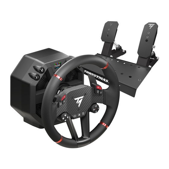
Box contents T598 Servo Base SportCar Steering Wheel Raceline Pedals LTE... -
Page 8: Features
Features ❶ ❷ Screen ❸ button (Settings) ❹ L3 and R3 buttons ❺ MODE button Quick release wheel rim attachment system... - Page 9 ❼ ❻ On/Off button ❽ Power port Shifter* or handbrake* connection port ❾ Pedal set connection port ❿ Unused port — Feature available soon ⓫ USB-C port *Sold separately...
- Page 10 ⓬ L2 and R2 buttons ⓭ Action buttons ⓮ Directional buttons ⓯ Encoder selector, E+, E- and EP functions, and LED indicating the active encoder ⓰ SHARE button on PS4 ® consoles / CREATE button on consoles ® ⓱ PS button ⓲...
- Page 11 ⓳ Quick release wheel rim attachment system ⓴ Magnetic paddle shifters...
- Page 12 Spring retaining rod Brake pedal jack connector Accelerator pedal jack connector Brake pedal spring (one support, one buffer, one washer and two springs (weak or strong resistance)) Accelerator pedal spring (one support and one spring)
- Page 13 Carpet Grip non-slip supports Pedal stop rods (one rod, one wing nut, one curved washer and one washer) Double jack/RJ12 cable Base mounting bracket Rubber protective cover Power supply cables...
-
Page 14: Information Regarding Use Of The
Information regarding use of the wheel rim Documentation Before using this product, carefully read this documentation again and keep it for future reference. - Page 15 2. Uninstall the old PC driver, and then install the new PC driver available in the Drivers section. Also install the My Thrustmaster Panel software available in the Software section. Once this is done, restart the computer. 3. Open...
- Page 16 Electrical shock − Keep the product in a dry location and do not expose it to dust or sunlight. − Use the product in an environment with a temperature between 15°C and 30°C. − Do not twist or pull on the connectors and cables. −...
- Page 17 any abnormal sounds, heat or odors), stop using the device immediately, power off the base, unplug the power supply cable from the wall outlet and disconnect the other cables. − When you are not using the base, power it off using the On/Off button.
- Page 18 Power supply − Only use the power supply indicated in the user manual. − Only use the power supply with the electrical network voltage and frequency indicated on the power supply’s rating plate. Securing the gaming area − Do not place any object in the gaming area which may disrupt the practice of the user, or which may provoke inappropriate...
- Page 19 Information regarding the power supply Published Value Unit information Manufacturer’s GUILLEMOT name or CORPORATION S.A. trademark 414 196 758 R.C.S. Business number Vannes Address 2 Rue du Chêne Héleuc 56910 Carentoir France Model identifier A1001-1636000D Input voltage 100 – 240 Input AC 50 –...
- Page 20 Heat dissipation surface To ensure optimal heat dissipation, you must comply with all of the following points: − Position the base at least 10 cm away from any wall surfaces. − Do not place the base in any tight spaces. −...
- Page 21 During intensive use, you may notice a slight odor emanating from the base. This specific case mainly occurs with new products: it is normal, and subsides over time.
- Page 22 Injuries due to Force Feedback and repeated movements Playing with a Force Feedback racing wheel may cause muscle or joint pain. To avoid any problems: − Avoid overly-long gaming periods (more than 2 hours). − Take a 10 to 15-minute break after each hour of play. −...
- Page 23 Risk of unforeseen, powerful and rapid rotations: never place a hand or an arm through the openings in the wheel rim, or in the wheel’s trajectory of rotation. When using the product, always leave both hands correctly positioned on the wheel without ever completely letting go.
-
Page 24: Information Regarding Use Of The
For safety reasons, never use the pedal set with bare feet or while wearing only socks on your feet. Thrustmaster ® disclaims all responsibility in the event of injury resulting from use of the pedal set without... - Page 25 Electrical shock − Keep the product in a dry location and do not expose it to dust or sunlight. − Do not twist or pull on the connectors and cables. − Follow the connection directions. − Do not spill any liquid on the product or its connectors.
- Page 26 Injuries due to repeated movements Playing with a pedal set may cause muscle or joint pain. To avoid any problems: − Avoid overly-long gaming periods (more than 2 hours). − Take a 10 to 15-minute break after each hour of play. −...
- Page 27 Pedal set pinch hazard when playing − Keep the pedal set out of children’s reach. − During gaming sessions, never place your fingers (or other parts of your body) on or near the pedal arms.
-
Page 28: Installing The Base On A Table
Installing the base on a table or desk Before each use, verify that the base is still properly attached to the support, as per this manual’s instructions. Solidity of the support Take into account your support’s material, in order to ensure that it is possible to mount a high-torque base on the support. - Page 29 1. Position the mounting plate underneath the base, lining up the perforations. 2. Tighten the four mounting screws clockwise using the 5-mm Allen wrench.
- Page 30 3. Install the rubber protective cover at the back of the mounting plate, in order to protect your support. 4. Insert the brackets on each side of the mounting plate. Make sure that the bracket slots are correctly positioned on the plate. 5.
-
Page 31: Installing The Base On A Cockpit
Installation plans for cockpits are available at: https://support.thrustmaster.com/product/T598p/ in the Manual section. -
Page 32: Installing The Wheel Rim On
Installing the wheel rim on the base 1. Make sure the base is powered off and the base’s locking lever is in the open position. 2. Insert the wheel rim into the base. - Page 33 3. Lower the locking lever. Pinch hazard Do not leave your finger in the locking system when lowering the lever. Before each use, verify that the base is still properly attached to the support, as per the manual’s instructions for the base.
-
Page 34: Assembling The Pedal Set
Assembling the pedal set Pinch hazard Before assembling the pedal set, make sure your fingers are not between the pedal arms and the base of the pedal set when lowering the pedals. Required elements:... - Page 35 1. Insert stop into corresponding perforations in the base of the pedal set: the rod and the curved washer on one side of the pedal, the washer and wing nut on the other side. Repeat the procedure on the other pedal. 2.
- Page 36 Brake pedal: The parts making up the brake pedal spring are in the BRAKE box. There are two springs with different resistances: − A1 spring (long, black): weak resistance; − A2 spring (short, grey): strong resistance. Set aside the spring that you do not want to use. 3.
- Page 37 4. Compress the brake pedal spring using the support, to insert the retaining rod into the slots in the pedal set base. To adjust the brake pedal’s resistance, you can place the spring retaining rod in different positions. For more information on adjusting the brake pedal’s Pedal set mechanical resistance, please read the settings...
- Page 38 Accelerator pedal: The parts making up the accelerator pedal spring are in the GAS box, which contains a single B1 spring (very long, grey). 5. Insert all the parts of the accelerator pedal spring on the metal rod in the following order: spring and support.
- Page 39 To adjust the accelerator pedal’s resistance, you can place the spring retaining rod in different positions. For more information on adjusting the accelerator Pedal set pedal’s resistance, please read the mechanical settings section. A video showing assembly of the pedal set is available here: https://support.thrustmaster.com/product/T598p/.
-
Page 40: Pedal Set Mechanical Settings
Pedal set mechanical settings Adjusting the height of the pedals The height of the brake pedal and accelerator pedal can be adjusted. There are four possible positions for each pedal. Brake pedal: Accelerator pedal:... - Page 41 1. Use the included T20 Torx wrench to unscrew the two screws holding the pedal head in place. 2. Select the new pedal head position. 3. Reinsert and retighten the two screws holding the pedal head in place.
- Page 42 Modifying the brake pedal’s resistance Two springs are included for adjusting the brake pedal’s resistance: − A1 spring (long, black): weak resistance; − A2 spring (short, grey): strong resistance. The three slots at the back of the pedal set base are used to adjust the resistance setting.
- Page 43 1. To release the spring retaining rod from the slots, compress the spring using the support. 2. Remove all of the pedal spring’s parts. 3. Insert the new spring onto the pedal’s metal rod.
- Page 44 4. Insert the other parts of the brake pedal spring onto the metal rod in the following order: washer, buffer and support. On the support, the UP marking must point upwards. 5. To insert the spring retaining rod into the slots (P1, P2 or P3), compress the spring using the support.
- Page 45 Modifying the accelerator pedal’s resistance Only one spring is included for the accelerator pedal (B1 spring: very long, grey, weak resistance). The three slots at the back of the pedal set base are used to adjust the resistance setting. B1 spring Position Resistance...
- Page 46 1. To release the spring retaining rod from the slots, compress the spring using the support. 2. To insert the spring retaining rod into the slots (P1, P2 or P3), compress the spring using the support. To prevent any calibration problems, we recommend that you restart the base after changing the spring.
-
Page 47: Carpet Grip Non-Slip Supports
Carpet Grip non-slip supports The Carpet Grip non-slip supports prevent the Raceline Pedals LTE pedal set from moving when used on a carpet or rug. Do not use the Carpet Grip non-slip supports on a soft floor or parquet flooring, as this may damage the floor covering (e.g., scuffs, scratches). - Page 48 Assembly To install the Carpet Grip non-slip supports, clip them to the back of the pedal set. To ensure that the supports are effective, position the teeth towards the back of the pedal set.
- Page 49 Disassembly To remove the Carpet Grip non-slip supports: 1. Release the springs from the notches. 2. Press the clip of each non-slip support. Do not pull on the sides of the Carpet Grip non-slip supports to remove them. You risk breaking the supports.
-
Page 50: Installation
Installation On a PlayStation 4 console ® *Not included... - Page 51 1. Power on your PlayStation 4 console. ® 2. Connect the double jack/RJ12 cable to the RJ12 connector on the base and the Raceline Pedals LTE pedal set. The jack connector with the B marking (Brake) connects to the brake pedal. The jack connector with the G marking (Gas) connects to the accelerator pedal.
- Page 52 7. The base’s screen turns on. 8. Press the MODE button.
- Page 53 9. Use directional buttons select PLAYSTATION MODE 1 (blue) on the screen. PlayStation games, must select ® PLAYSTATION MODE 1 (blue).
- Page 54 Press the MODE button to confirm the selection. Your selection is saved in the base’s internal memory. If the selected mode is identical to the mode that was previously selected, the screen you were on before selecting the mode is displayed. If the selected mode is different from the mode that was previously selected, the racing wheel will restart and perform a self-calibration.
- Page 55 During the racing wheel’s self-calibration phase, make sure not to put your hands on the wheel rim. You are now ready to play!
-
Page 56: On A Playstation®5 Console
On a PlayStation 5 console ® *Not included... - Page 57 1. Power on your PlayStation 5 console. ® 2. Connect the double jack/RJ12 cable to the RJ12 connector on the base and the Raceline Pedals LTE pedal set. The jack connector with the B marking (Brake) connects to the brake pedal. The jack connector with the G marking (Gas) connects to the accelerator pedal.
- Page 58 7. The base’s screen turns on. 8. Press the MODE button to select the PlayStation ® mode that is compatible with your game.
- Page 59 PLAYSTATION MODE 1 (blue). − For PlayStation 5 games: to see if your game is ® compatible with PLAYSTATION MODE 1 (blue) or PLAYSTATION MODE 2 (red), go to https://support.thrustmaster.com/product/T598p/ In the Games settings section, select PlayStation ® Games list.
- Page 60 Press the MODE button to confirm the selection. Your selection is saved in the base’s internal memory. If the selected mode is identical to the mode that was previously selected, the screen you were on before selecting the mode is displayed. If the selected mode is different from the mode that was previously selected, the racing wheel will restart and perform a self-calibration.
- Page 61 During the racing wheel’s self-calibration phase, make sure not to put your hands on the wheel rim. You are now ready to play!
-
Page 62: On Pc
On PC* *PC compatibility (Windows ® 10/11) not tested or endorsed by Sony Interactive Entertainment. **Not included... - Page 63 1. Go to: https://support.thrustmaster.com/product/T598p/. 2. Download and install the PC driver in the Drivers section and the My Thrustmaster Panel software in the Software section. 3. Once the PC driver has been installed, connect the double jack/RJ12 cable to the RJ12 connector on the base and the Raceline Pedals LTE pedal set.
- Page 64 7. The base’s screen turns on. 8. Press the MODE button to select the PC mode. 9. Use the directional buttons to select PC MODE on the screen.
- Page 65 Press the MODE button to confirm the selection. Your selection is saved in the base’s internal memory. If the selected mode is identical to the mode that was previously selected, the screen you were on before selecting the mode is displayed. If the selected mode is different from the mode that was previously selected, the racing wheel will restart and perform a self-calibration.
- Page 66 My Thrustmaster Panel software...
- Page 67 The My Thrustmaster Panel software lets you: − view the serial number (SERIAL NUMBER) of your base; − view the driver version (DRIVER) installed on your − view the firmware version (FIRMWARE) installed on your base; − view the firmware version (FIRMWARE) installed on the wheel rim connected to your base;...
-
Page 68: Updating The Firmware
Updating the firmware Your base’s firmware version is listed on the Overview page of the My Thrustmaster Panel software. - Page 69 When an update is necessary: − On the Home page, a banner announcing NEW UPDATE AVAILABLE! appears on the icon of the base. This message may also mean that a new driver package is available. − On the Overview page, a red exclamation point appears next to the firmware version.
- Page 70 To update the base’s firmware: 1. In My Thrustmaster Panel, on the Overview page, click APPLY UPDATES. 2. Power off the base by pressing the On/Off button located on the back of the base (released position). In My Thrustmaster Panel, click NEXT.
- Page 71 (Settings) buttons, power on the base by pressing the On/Off button located on the back of the base (pushed-in position). In My Thrustmaster Panel, click NEXT. 4. Release the L3 and (Settings) buttons. Boot mode is properly activated if the base’s screen...
- Page 72 5. In My Thrustmaster Panel, click DONE to start the firmware update. Once the update has started, do not disconnect or power off the base. Do not close or exit the My Thrustmaster Panel software. 6. Once the update is complete, power off the base by pressing the On/Off button, and then power the base back on.
- Page 73 Your base’s firmware is now up to date.
-
Page 74: Automatic Calibration Of The Racing Wheel
Automatic calibration of the racing wheel and pedals The wheel rim automatically self-calibrates when you plug the racing wheel into a wall outlet, power it on using the On/Off button, and connect the racing wheel’s USB connector to the PlayStation 4 / PlayStation 5 console ®... - Page 75 Always connect the pedal set before connecting the racing wheel to the console. Once the racing wheel’s self-calibration is complete and the game has been started, the pedals are automatically calibrated after a few presses. Never press the pedals when powering on your console or your PC, starting a game, changing the compatibility mode or installing a wheel rim on the base when the base is powered on, or during the racing wheel’s self-...
-
Page 76: Or Playstation®5 Consoles
10. Mapping PlayStation ® consoles PlayStation ® consoles BASE SHARE (PS4™) CREATE (PS5™) OPTIONS... -
Page 77: Using The Encoders
The following functions and LED colors are associated with the encoders: Encoders E1, E2, E3 and E4 work in games compatible with Thrustmaster encoders. The list of compatible games is available here: https://support.thrustmaster.com/product/T598p/ (in the Games settings section). This list is regularly... -
Page 78: 11. Mapping For Pc
11. Mapping for PC BASE... -
Page 79: Using The Encoders
The following functions and LED colors are associated with the encoders: Encoders E1, E2, E3 and E4 work in games compatible with Thrustmaster encoders. The list of compatible games is available here: https://support.thrustmaster.com/product/T598p/ (in the Games settings section). This list is regularly... -
Page 80: 12. Screen Operation
12. Screen operation The base’s screen lets you: Select the compatibility mode; − Access the Settings or Telemetry submenus; − Change the settings for the wheel rim, the base − and the pedal set, as well as the screen’s brightness; Select the telemetry information to be displayed. -
Page 81: Selecting The Compatibility Mode
Selecting the compatibility mode The base has three compatibility modes. Make sure to select the appropriate mode based on your platform (PlayStation 4 consoles, PlayStation 5 consoles or ® ® PC) and the game that you are playing. Mode Color bar PLAYSTATION MODE 1 PLAYSTATION MODE 2 PC MODE... - Page 82 ® ® to see if your game is compatible with PLAYSTATION MODE 1 (blue) or PLAYSTATION MODE 2 (red), go to: https://support.thrustmaster.com/product/T598p/ In the Games settings section, select PlayStation ® Games list. To select the mode corresponding to your platform: 1.
- Page 83 3. Press the MODE button to confirm the selection. Your selection is saved in the base’s internal memory. If the selected mode is identical to the mode that was previously selected, the screen you were on before selecting the mode is displayed. If the selected mode is different from the mode that was previously selected, the racing wheel will restart and perform a self-calibration.
-
Page 84: Accessing The Settings Or Telemetry
Accessing the Settings or Telemetry submenu For safety reasons and to avoid any risk of injury, we very strongly advise you to pause the game before pressing the button (Settings). - Page 85 To display the Settings or Telemetry submenu selection screen: 1. Press the button (Settings). The following screen is displayed: 2. Press the L3 button to select the Settings submenu. The following screen is displayed: Press the R3 button to select the Telemetry submenu.
-
Page 86: Settings Submenu
Settings submenu The Settings submenu lets you display information about the base, the wheel rim and the pedal set, and lets you change the associated settings. To access the Settings submenu, press the button (Settings), then press the L3 button. The following screen is displayed: ❶... - Page 87 To navigate through the Settings submenu: − Use the directional buttons. To change the value of a setting: − Use the directional buttons. To confirm the value of a setting: − Press the button (Settings). You will exit the Settings submenu and the screen will display the telemetry information (GEAR screen by default).
-
Page 88: Adjusting The Brightness
Adjusting the brightness This screen lets you change the overall brightness of the screen’s display. Three settings are possible: − - 1 − 0 (default setting) − + 1... - Page 89 Settings of the base...
- Page 90 Firmware of the base This screen shows the firmware version of the base.
- Page 91 Force Feedback profiles This screen is used to select the Force Feedback profile. You have the choice between four saved profiles, ranging from the least aggressive Force Feedback to the most aggressive: FFB D (default); FFB 1; FFB 2; FFB 3. The saved settings are: FFB D FFB 1...
- Page 92 You can change the FFB 1, FFB 2 and FFB 3 profiles by changing the settings of the base. The profiles are saved in the base’s internal memory. Use the Factory Reset screen to restore the saved settings of the FFB 1, FFB 2 and FFB 3 profiles. The FFB D profile cannot be modified.
- Page 93 Depending on the Force Feedback profile selected and the settings defined, the base may generate a whistling sound. This is normal and linked to the combination of several parameters aimed at increasing the motor’s responsiveness. The greater the responsiveness, the louder the whistling sound.
- Page 94 Master gain (overall Force Feedback) This screen lets you adjust the overall power of the Force Feedback effects (master gain). This value ranges from 0% to 100%, in increments of 5. Mode This screen is used to select the driving mode and change the Force Feedback responsiveness.
- Page 95 Friction This screen lets you adjust the motor’s friction when the wheel rim is turning slowly or not moving. There are four settings to choose from, ranging from no resistance to very strong resistance: OFF; LOW; MID; HIGH. This setting can be used to avoid oscillating movements.
- Page 96 Boost low (light to medium effects) This screen lets you adjust the light to medium Force Feedback effects (e.g., rumble strips on the edge of the track, road texture). There are five settings to choose from: - 2; - 1; 0; + 1; + 2. Boost high (medium to high effects) This screen lets you adjust the medium to high Force Feedback effects (collision with another vehicle or a wall,...
- Page 97 Speed This screen lets you change the motor’s rotation speed (for example: when you release the wheel rim and it continues to turn). There are four settings to choose from, ranging from slow to very fast rotation speed: LOW; MID; HIGH;...
- Page 98 Damper This screen lets you adjust the Force Feedback damper (rotation of the wheel rim that is more smooth or less smooth). This value ranges from 0% to 100%, in increments of 10. Reducing the damper force increases, improves and optimizes the overall feel of the Force Feedback.
- Page 99 Spring This screen lets you adjust the spring force (return to central position of the wheel rim when there is no Force Feedback). The default spring value is 0%. This value ranges from 0% to 100%, in increments of 10. You should only change the spring value in games that do not support Force Feedback.
- Page 100 OFF (default); LOW; MID; HIGH. The Gear jolt effect is only functional in games compatible with the Thrustmaster telemetry SDK. The effect only works in games where telemetry information is displayed on the base’s screen.
- Page 101 End stop (virtual end stop) This screen lets you change the force of the virtual end stop (end stop damping). There are three settings to choose from, ranging from low to very strong force: LOW; MID; HIGH (default).
- Page 102 Wheel rim settings...
- Page 103 Wheel rim firmware This screen shows the firmware version of the wheel rim. The firmware version is only displayed when a wheel rim is installed on the base and the information is available.
-
Page 104: Rotation Angle
Rotation angle This screen lets you set the wheel rim’s angle of rotation. There are seven settings to choose from: 180°; 270°; 360°; 540°; 900°; 1080°; Auto (default). − When the wheel rim’s angle of rotation is set to AUTO, the angle is automatically adjusted by the game according to the vehicle being used. - Page 105 Test and central position This screen lets you test the analog paddles* and the wheel rim’s axis and reset the central position of the wheel rim (only when needed). Rotation axis L.ana = Left analog R.ana = Right analog paddle* paddle* *Only available for wheel rims with analog paddles...
- Page 106 When testing an analog paddle*, the gauge associated with this paddle fills up. When testing the rotation axis, the gauge associated with the wheel rim fills up: − 0%: you have reached the left end stop; − 50%: central position of the wheel rim; −...
- Page 107 Pedal set settings...
- Page 108 Pedal set firmware This screen will show the firmware version of certain pedal sets in the future.
- Page 109 This screen lets you select the type of pedal set being used. There are three types of pedal sets to choose from: − TRLP: for the Raceline Pedals LTE pedal set, included with T598; − T3PA: for the T2PM*, T3PA* and T3PM* pedal sets (without a Load Cell force sensor);...
- Page 110 Pedal set configuration This screen lets you select the pedal set configuration. There are two positions to choose from: (default): normal position; − : inverted position. − − The inverted position is only available with a 3-pedal pedal set. − In the inverted position, the accelerator and clutch pedals are reversed.
-
Page 111: Resetting The Settings
Resetting the settings... - Page 112 This screen lets you reset the settings for the base, wheel rim, pedal set, screen and telemetry. To reset the settings: 1. Press . The following screen is displayed: 2. Press to confirm the reset. When the settings have been reset, the following screen is displayed for five seconds: Press to refuse the reset.
-
Page 113: Telemetry Submenu
Telemetry submenu The Telemetry submenu lets you select the telemetry information displayed in the game: speed, position, number of laps, session time, engine speed, etc. To access the Telemetry submenu, press the button (Settings), then press the R3 button. In the Telemetry submenu, the following screen is displayed: ❶... - Page 114 During the game, the following screen is displayed: ❶ ❷ Telemetry information RPM strip ❸ Selected compatibility mode To navigate through the Telemetry submenu and select the telemetry information to be displayed: − Use the directional buttons. To confirm your selection: −...
- Page 115 Telemetry and compatibility The telemetry information is only displayed in games that are compatible with the Thrustmaster SDK. The list of compatible games is available here: https://support.thrustmaster.com/product/T598p/ (in the Games settings section). This list is regularly updated. Updating the firmware...
- Page 117 GT or Formula mode This screen lets you select the display mode for the engine speed (RPM). There are two modes to choose from: − GT mode (red): from the extremities to the center; − Formula mode (blue, default): from left to right. Examples of displays: GT mode Formula mode...
- Page 118 Gear This screen lets you display information about the current gear and, depending on the games, the flag (FLAG) and the pit (PIT). Example of display: Speed This screen lets you display the vehicle’s speed. Example of display:...
- Page 119 Position This screen lets you display the position in the ranking. Example of display: This screen lets you display the number of laps completed. Example of display:...
- Page 120 Time This screen lets you select the time display mode (TIME). There are three modes to choose from: − TIME CL: displays the current lap time (CURR LAP); − TIME LL: displays the last lap time (LAST LAP); − TIME BL: displays the personal best lap time (BEST LAP).
- Page 121 Examples of displays: TIME CL TIME LL TIME BL Use the directional buttons to select a mode, then press the button (Settings) to confirm your selection. Engine speed This screen lets you display the engine speed (RPM). Example of display:...
-
Page 122: 13. Faq And Technical Support
13. FAQ and technical support Do you have questions regarding the T598 Servo Base base, the SportCar Steering Wheel wheel rim or the Raceline Pedals LTE pedal set, or are you experiencing technical problems? If so, visit the Thrustmaster technical support website: https://support.thrustmaster.com/product/T598p/...
Need help?
Do you have a question about the T598 and is the answer not in the manual?
Questions and answers