Table of Contents
Advertisement
Available languages
Available languages
Advertisement
Table of Contents
Troubleshooting

Related Manuals for Thrustmaster T500RS


Summary of Contents for Thrustmaster T500RS
- Page 1 Europe, Middle East North America/ Norteamérica ENGLISH FRANÇAIS ENGLISH DEUTSCH FRANÇAIS NEDERLANDS ESPAÑOL ITALIANO Latin America/ ESPAÑOL América Latina PORTUGUÊS ENGLISH ESPAÑOL ΕΛΛΗΝΙΚΑ PORTUGUÊS TÜRKÇE Asia Paci c POLSKI 日本語 한국어 ENGLISH 中文 ENGLISH...
- Page 2 For: PlayStation ® User Manual 1/20...
-
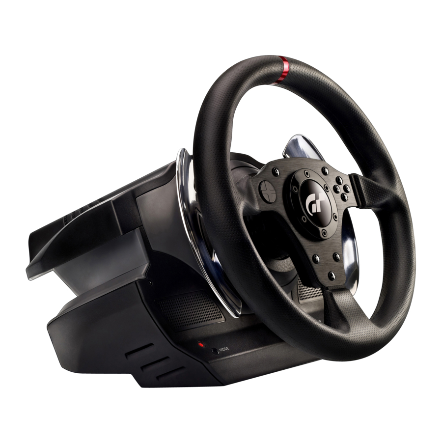
Page 3: Technical Features
TECHNICAL FEATURES 1 Steering wheel base 2 Steering wheel MODE button 3 D-pad Large screw thread (for the clamping 4 2 digital gearshift levers (Up & Down) system and the clamp screw) 5 Action buttons Clamping system 10 Metal clamp screw 11 Pedal set cable and connector 13 Mains adaptor 12 Steering wheel cable and USB connector... - Page 4 11 Pedal set cable and connector 18 Removable “Realistic Brake” MOD 15 Removable foot rest (not installed by default) 16 Arch 19 2mm Allen key, supplied 17 Removable pedal set 20 2.5mm Allen key, supplied 17 Metal head 22 Pedal arm 21 Plastic Head Support 23 Removable metal stop (not installed by default)
- Page 5 * Do not let any dust build up on the air vents. For safety reasons, never use the pedal set with bare feet or while wearing only socks on your feet. THRUSTMASTER DISCLAIMS ALL RESPONSIBILITY IN THE ® EVENT OF INJURY RESULTING FROM USE OF THE PEDAL SET WITHOUT SHOES.
- Page 6 Warning – Injuries due to force feedback and repeated movements Playing with a force-feedback steering wheel may cause muscle or joint pain. To avoid any problems: * Avoid lengthy gaming periods. * Take 10 to 15 minute breaks after each hour of play. * If you feel any fatigue or pain in your hands, wrists, arms, feet or legs, stop playing and rest for a few hours before you start playing again.
- Page 7 Warning – Pedal set pinch hazard when playing * Keep the pedal set out of children’s reach. * Do not remove the protections placed on the pedal arms. * During games, never place your fingers near the sides of the pedals. * During games, never place your fingers near the rear base of the pedals.
-
Page 8: Installing The Wheel
INSTALLING THE WHEEL Fixing the wheel to a Table or Desk 1. Place the wheel on a table or another flat surface. 2. Place the clamp screw (10) in the table clamp (9) then screw the clamping unit (anti-clockwise) into the large screw thread (8) located under the wheel until it is perfectly stable. ALWAYS NEVER CAUTION: Never screw the clamp screw into the clamping system on its own! - Page 9 ASSEMBLY / DISASSEMBLY To tighten: Screw anti- clockwise To loosen: Unscrew clockwise Attaching the steering wheel and pedal set to a cockpit 1. Place the steering wheel on the Cockpit’s tablet. 2. Tighten 2 “M6” screws (not supplied) into the Cockpit table and into the 2 small screw threads under the wheel.
- Page 10 - In order for the T500 RS wheel to work with Gran Turismo® 5, you must install the automatic updates for the game (available once you are connected to the Internet). - There are various tips and help features (not included in this manual) available on the website http://ts.thrustmaster.com in the Technical Support category. 9/20...
-
Page 11: Configuring The Pedals
CONFIGURING THE PEDALS Each of the 3 pedals features: - A “Metal Head (17)” with several perforations (9 for the Accelerator – 6 for the Brake – 6 for the Clutch) - A “Plastic Head Support (21)” (between the head and the arm) with 4 perforations - A “Metal Arm (22)”... - Page 12 Adjusting the Pedal SPACING - Using the 2.5mm Allen key supplied (20) loosen the 2 screws holding the “Metal Head (17) and its support (21)” - Once you have done so, select your position (to the left, in the center or to the right) then tighten the screws.
- Page 13 To restore your protection against pinch hazards, you must remove the metal stop and reinstall the transparent plastic pinch-hazard protector in its former location. THRUSTMASTER® DISCLAIMS ALL RESPONSIBILITY FOR ANY INJURIES CAUSED BY REMOVAL OF THE PINCH-HAZARD PROTECTOR OR INSTALLATION OF THE METAL STOP - Unscrew the 2 screws holding the pinch-hazard protector on the brake pedal arm.
- Page 14 - Select your position (up, in the center or down) then tighten the screws using the 2.5mm Allen key supplied (20). Long run position Short run position & High resistance (default) & Low resistance Number of possible travel or resistance positions: - Long travel with resistance of around 10Kg (22lbs) - Medium travel with resistance of around 8.5Kg (18.7lbs) - Short travel with resistance of around 7Kg (15.4lbs)
- Page 15 To restore your protection against pinch hazards, you must remove the metal stop and reinstall the transparent plastic pinch-hazard protector in its former location. THRUSTMASTER® DISCLAIMS ALL RESPONSIBILITY FOR ANY INJURIES CAUSED BY REMOVAL OF THE PINCH-HAZARD PROTECTOR OR INSTALLATION OF THE METAL STOP This MOD enables different sensations and resistance when braking.
- Page 16 - Install the MOD fully and tightly into the bottom of the “Metal Stop” cavity. - For strong resistance: position the MOD against the Upper wall. - For even stronger resistance: position the MOD against the Lower wall. Position against the Upper wall (Resistance of around 14Kg/30.8lbs) Position against the Lower wall (Resistance of around 16Kg/35.2lbs)
- Page 17 TURNING THE PEDAL SET POSITION OVER The “T500 RS” pedal set has a unique design (patent pending) that allows for a choice of 2 positions: - Floor position (F1 type) - Suspended position (GT/Rally type) By default, the pedal set is delivered in “Floor” position (F1 type) Floor position (F1 type) Suspended position (GT/Rally type) REVERSING THE PEDAL SET PHYSICALLY...
- Page 18 - Turn the pedal set over 90° then tighten the "Foot Rest" again on the 4 screw threads located on the "Arch (16)”. - Using the 2.5mm Allen key (20) loosen the 3 "Metal Heads (17)” to turn them over 180° and reverse the Accelerator head and the Clutch head.
- Page 19 (the LED colour tells you the position you have chosen) LED (6) PEDAL SET POSITION colour ON THE FLOOR (F1 type) (installed by default) SUSPENDED (GT/Rally type) GREEN Once you have done this the selected position is stored immediately in the wheel’s internal memory TECHNICAL SUPPORT http://ts.thrustmaster.com 18/20...
- Page 20 Thrustmaster product according to applicable laws of the country in which the consumer was domiciled on the date of purchase of the Thrustmaster product (if no such action exists in the corresponding country, then the warranty period shall be one (1) year from the original date of purchase of the Thrustmaster product).
- Page 21 COPYRIGHT © 2015 Guillemot Corporation S.A. All rights reserved. Thrustmaster® is a registered trademark of Guillemot Corporation S.A. “ ”, “PlayStation”, “ ”, and “ ” are registered trademarks of Sony Computer Entertainment Inc. All rights reserved. and GRAN TURISMO are registered trademarks of Sony Computer Entertainment Inc.
- Page 22 Pour : PlayStation ® Manuel de l’utilisateur 1/20...
-
Page 23: Caractéristiques Techniques
CARACTÉRISTIQUES TECHNIQUES 1 Base du volant Voyant lumineux 2 Roue du volant Bouton MODE 3 Croix multidirectionnelle Gros « pas de vis » (pour le système de 4 2 leviers séquentiels de changement de vitesse fixation et la vis de serrage) (Up &... - Page 24 11 Câble et connecteur du pédalier 18 Mod « Realistic Brake » amovible 15 Repose-pieds amovible (non installé par défaut) 16 Arceau 19 Clé Allen 2 mm fournie 17 Tête des pédales amovible 20 Clé Allen 2,5 mm fournie 17 Tête métallique 22 Bras métallique 21 Support de tête plastique 23 Butée métallique amovible...
- Page 25 * Ne laissez pas la poussière s’accumuler sur les grilles d’aération. Pour des raisons de sécurité, ne jouez pas pieds nus ou en chaussettes lorsque vous utilisez le pédalier. THRUSTMASTER DECLINE TOUTE RESPONSABILITE EN CAS DE ® BLESSURE SUITE A UNE UTILISATION DU PEDALIER SANS CHAUSSURES.
- Page 26 Avertissement – Blessures dues au retour de force et aux mouvements répétitifs (suite) * Si les symptômes ou les douleurs indiqués ci-dessus persistent lorsque vous reprenez le jeu, arrêtez de jouer et consultez votre médecin. * Laissez hors de portée des enfants. * Lors des phases de jeu, laissez toujours vos deux mains correctement positionnées sur le volant sans jamais le lâcher complètement.
- Page 27 Avertissement – Risque de pincement au niveau du pédalier lors des phases de jeu * Laissez le pédalier hors de portée des enfants. * Ne retirez pas les protections placées sur les bras des pédales. * Lors des phases de jeu, ne placez jamais vos doigts sur ou à proximité des côtés des pédales. * Lors des phases de jeu, ne placez jamais vos doigts sur ou à...
-
Page 28: Installation Du Volant
INSTALLATION DU VOLANT Fixer le volant sur une table ou un bureau 1. Placez le volant sur une table ou autre surface plane. 2. Placez la vis de serrage (10) dans le système de fixation (9), puis vissez l’ensemble (dans le sens inverse des aiguilles d’une montre) dans le gros «... - Page 29 MONTAGE / SENS DEMONTAGE Pour serrer : Vissez dans le sens inverse des aiguilles d’une montre Pour desserrer : Dévissez dans le sens des aiguilles d’une montre Fixer le volant et le pédalier sur un cockpit 1. Placez la base du volant sur la tablette du cockpit 2.
- Page 30 - Pour que le volant T500 RS fonctionne avec Gran Turismo® 5, il est indispensable d’installer les mises à jour automatiques du jeu (disponibles lorsque vous êtes connecté à Internet). - Aides & astuces diverses (non notifiés dans ce manuel) disponibles sur le site http://ts.thrustmaster.com dans la catégorie Support Technique. 9/20...
- Page 31 REGLAGES DU PEDALIER Chacune des 3 pédales comprend : - Une « tête métallique (17) » avec plusieurs perforations (9 pour l’accélérateur – 6 pour le frein – 6 pour l’embrayage) - Un « support de tête plastique (21) » (situé entre la tête et le bras) avec 4 perforations - Un «...
- Page 32 Ajuster l’ECARTEMEMENT des pédales - A l’aide de la clé Allen 2,5 mm fournie (20), dévissez les 2 vis maintenant la « tête métallique (17) et son support (21) ». - Choisissez ensuite votre position (à gauche, au centre ou à droite), puis revissez le tout. Exemples ici avec la pédale de frein : Position à...
- Page 33 Pour rétablir cette protection, vous devez retirer la butée métallique installée et refixer la protection en plastique transparent dans son emplacement d’origine. THRUSTMASTER® DÉCLINE TOUTE RESPONSABILITÉ EN CAS DE BLESSURE SUITE AU RETRAIT DE LA PROTECTION ANTI-PINCEMENT OU L’INSTALLATION DE LA BUTÉE - Dévissez les 2 vis maintenant la protection anti-pincement, en bas du bras métallique de la pédale...
- Page 34 - Sélectionnez votre position (en haut, au centre ou en bas), puis serrez les vis à l’aide de la clé Allen 2,5 mm fournie (20). Position course longue Position course courte et forte résistance (par défaut) et faible résistance Nombre de positions de course ou de résistance possibles : - Course longue avec résistance d’environ 10Kg - Course moyenne avec résistance d’environ 8,5Kg - Course courte avec résistance d’environ 7Kg...
- Page 35 Pour rétablir cette protection, vous devez retirer la butée métallique installée et refixer la protection en plastique transparent dans son emplacement d’origine. THRUSTMASTER® DÉCLINE TOUTE RESPONSABILITÉ EN CAS DE BLESSURE SUITE AU RETRAIT DE LA PROTECTION ANTI-PINCEMENT OU L’INSTALLATION DE LA BUTÉE Ce MOD permet d’apporter un feeling et une résistance différents lors des freinages.
- Page 36 - Installez le MOD complètement et parfaitement au fond de la cavité de la « butée métallique ». - Pour une résistance forte : positionnez le MOD contre la paroi supérieure. - Pour une résistance encore plus forte : positionnez le MOD contre la paroi inférieure. Position contre la paroi supérieure (résistance d’environ 14 Kg) Position contre la paroi inférieure...
- Page 37 RETOURNER LA POSITION DU PEDALIER Le pédalier du « T500 RS » possède un design unique* (*Brevet en instance) permettant 2 positions au choix : - Position au plancher (type F1) - Position suspendue (type GT/Rallye) Par défaut, le pédalier est livré en position « Au plancher (Type F1) » Position au plancher (type F1) Position suspendue (type GT/Rallye) INVERSER PHYSIQUEMENT le pédalier...
- Page 38 - Retournez le pédalier de 90°, puis revissez le « repose-pieds » sur les 4 pas de vis situés sur l’« arceau (16) ». - A l’aide de la clé Allen 2,5 mm fournie (20), dévissez les 3 « têtes métalliques (17) » pour les retourner de 180°...
- Page 39 (la couleur du voyant lumineux vous indique la position choisie). Couleur du POSITION DU PEDALIER voyant lumineux (6) AU PLANCHER (Type F1) ROUGE (installée par défaut) SUSPENDUE (Type GT/Rallye) VERT La position choisie est ensuite instantanément enregistrée dans la mémoire interne du volant SUPPORT TECHNIQUE http://ts.thrustmaster.com 18/20...
- Page 40 Dans les pays de l’Union Européenne, ce délai est de deux (2) ans à compter de la délivrance du produit Thrustmaster. Dans les autres pays, la durée de la période de garantie correspond au délai pour intenter une action en conformité du produit Thrustmaster selon la législation en vigueur dans le pays où...
- Page 41 COPYRIGHT © 2015 Guillemot Corporation S.A. Tous droits réservés. Thrustmaster est une marque déposée de ® Guillemot Corporation S.A. “ ”, “PlayStation”, “ ” et “ ” sont des marques déposées de Sony Computer Entertainment Inc. Tous droits réservés. et GRAN TURISMO sont des marques déposées de Sony Computer Entertainment Inc.
- Page 42 Für: PlayStation ® Benutzerhandbuch 1/20...
-
Page 43: Technische Features
TECHNISCHE FEATURES 1 Lenkradbasis 2 Lenkrad MODE-Button 3 D-Pad Großes Schraubgewinde (für das 4 2 digitale Schalthebel (Hoch & Runter) Befestigungssystem und die 5 Actionbuttons Befestigungsschraube) Befestigungssystem 10 Metallene Befestigungsschraube 11 Kabel und Stecker für das Pedalset 13 Netzteil 12 Lenkradkabel und USB-Stecker 14 Netzkabel für das Netzteil 2/20... - Page 44 11 Pedalset-Kabel und Stecker 18 Abnehmbare “Realistic Brake” MOD 15 Abnehmbare Fußablage (werksseitig nicht vorinstalliert) 16 Gelenkbogenstück 19 2 mm Inbusschlüssel, beigelegt 17 Abnehmbarer Pedalkopf 20 2.5 mm Inbusschlüssel, beigelegt 17 Metallkopf 22 Metallarm 21 Plastikunterlegscheibe 23 Metallstopper (werksseitig nicht vorinstalliert) 3/20...
- Page 45 * Verdecken Sie die Basis niemals. * Lassen Sie die Belüftungsöffnungen niemals verstauben. Benutzen Sie das Pedalset aus Sicherheitsgründen niemals barfuß oder wenn Sie nur Socken tragen. THRUSTMASTER LEHNT JEDWEDE HAFTUNG IM FALLE EINER ® VERLETZUNG DURCH DAS PEDALSET DURCH NUTZUNG DESSELBEN OHNE SCHUHWERK AB.
- Page 46 Warnung – Schädigung durch Force Feedback und immer wiederholte Bewegungen Spielen mit einem Force-Feedback-Lenker kann Muskel- oder Gelenkschmerzen verursachen. Um jedwede Probleme zu vermeiden: * Vermeiden Sie längere Spielzeiten. * Machen Sie nach jeder Stunde im Spiel eine Pause von 10 bis 15 Minuten. * Falls Sie irgendwelche Ermüdungserscheinungen oder Schmerzen in Ihren Händen, Handgelenken, Armen Füßen oder Beinen verspüren, hören Sie zu spielen auf und ruhen sich für mehrere Stunden aus.
- Page 47 Warnung – Quetschungsgefahr am Pedalset während des Spielens * Bewahren Sie das Pedalset außerhalb der Reichweite von Kindern auf. * Entfernen Sie auf keinen Fall die Schutzabdeckungen an den Pedalarmen. * Stecken Sie während des Spielens niemals Ihre Finger seitlich in die Pedalseiten. * Stecken Sie während des Spielens niemals Ihre Finger in die hintere Basis der Pedale.
-
Page 48: Montage Des Lenkers
MONTAGE DES LENKERS Befestigung des Lenkers auf einem Tisch oder Schreibtisch 1. Plazieren Sie den Lenker auf einem Tisch oder einer anderen, ebenen Unterlage. 2. Stecken Sie die Befestigungsschraube (10) in das Befestigungssystem (9) und schrauben dann die Befestigungseinheit entgegen dem Uhrzeigersinn in das große Schraubgewinde (8) unterhalb des Lenkers, bis dieses perfekt stabil ist. - Page 49 AUFBAU / ABBAU Zum Befestigen: Entgegen des Uhrzeigersinns drehen Zum Lösen: Im Uhrzeigersinn drehen Befestigung des Lenkers und des Pedalsets in ein Cockpit 1. Plazieren Sie den Lenker auf die Unterlage des Cockpits. 2. Drehen Sie zwei “M6” Schrauben (nicht enthalten) durch die beiden kleinen Schrauböffnungen unterhalb des Lenkers in die Unterlage des Cockpits.
- Page 50 - Damit der T500 RS Lenker mit Gran Turismo® 5 funktioniert, müssen Sie die automatischen Updates für das Spiel installieren (verfügbar, sobald Sie mit dem Internet verbunden sind). - Es gibt zahlreiche Tips und Hilfen (nicht in diesem Handbuch verfügbar) auf der Website http://ts.thrustmaster.com in der Kategorie Technischer Support. 9/20...
-
Page 51: Konfiguration Der Pedale
KONFIGURATION DER PEDALE Jedes der drei Pedale verfügt über: - Einen “Metallkopf (17)” mit einigen Perforationen (9 für das Gas – 6 für die Bremse – 6 für die Kupplung) - Eine “Plastikunterlegscheibe (21)” (zwischen Kopf und Arm) mit 4 Perforationen - Einen “Metallarm (22)”... - Page 52 Anpassung des PedalZWISCHENRAUMS - Benutzen Sie den beigelegten 2.5 mm Inbusschlüssel (20), um die beiden Schrauben, die den “Metallkopf (17) und dessen Unterlegscheibe (21)” zu lösen - Ist dies bewerkstelligt, wählen Sie Ihre bevorzugte Position (links, mittig und rechts) und ziehen die Schrauben wieder fest.
- Page 53 Sie den Metallanschlag demontieren und die transparente Schutzabdeckung aus Plastik am ursprünglichen Platz montieren. THRUSTMASTER® LEHNT JEDWEDE HAFTUNG FÜR JEGLICHE VERLETZUNGEN, DIE DURCH DAS ENTFERNEN DER SCHUTZABDECKUNG ENTSTEHEN KÖNNEN, AB. - Lösen Sie die 2 Schrauben, die den Quetschschutz am Pedalarm halten.
- Page 54 - Wählen Sie Ihre Position (oben, mittig oder unten) und ziehen die Schrauben mittels des beigelegten 2,5 mm Inbusschlüssels (20) fest. Langer Hub & hoher Kurzer Hub & weniger Widerstand (werksseitig) Widerstand Anzahl der möglichen Hub- oder Widerstanspositionen: - Langer Hub mit Widerstand um 10 Kg - Mittlerer Hub mit Widerstand um 8.5 Kg - Kurzer Hub mit Widerstand um 7 Kg Hinweis: Je länger der Hub, desto höher der Pedalwiderstand...
- Page 55 Um wieder vor Quetschungsgefahren geschützt zu sein, müssen Sie den Metallanschlag demontieren und die transparente Schutzabdeckung aus Plastik am ursprünglichen Platz montieren. THRUSTMASTER® LEHNT JEDWEDE HAFTUNG FÜR JEGLICHE VERLETZUNGEN, DIE DURCH DAS ENTFERNEN DER SCHUTZABDECKUNG ENTSTEHEN KÖNNEN, AB. Diese MOD ermöglicht verschiedene Sinneseindrücke und Widerstände beim Bremsen.
- Page 56 - Lösen und entfernen Sie den “Metallstopper” (hinten am Pedalarm). - Montieren Sie die MOD vollständig und fest in den Boden der “Metallstopper” Vertiefung. - Für starken Widerstand: Positionieren Sie die MOD gegen die obere Wandung. - Für stärkeren Widerstand: Positionieren Sie die MOD gegen die untere Wandung. Position gegen die obere Wandung (Widerstand um 14 Kg) Position gegen die untere Wandung...
- Page 57 UMDREHEN DER PEDALSETPOSITION Das “T500 RS” Pedalset hat ein einzigartiges Design (zum Patent angemeldet), das die Wahl von zwei Positionen ermöglicht: - Bodenposition (F1-Typ) - Hängeposition (GT-/Rally-Typ) Werksseitig wird das Pedalset mit der “Bodenposition” ausgeliefert (F1-Typ) Bodenposition (Typ F1) Hängeposition (GT-/Rally-Typ) UMDREHEN DES PEDALSETS - Benutzen Sie den beigelegten 2 mm Inbusschlüssel (19), um die vier Schrauben, die die“...
- Page 58 - Drehen Sie das Pedalset um 90° und schrauben die "Abnehmbare Fußablage" in die vier Gewindegänge am "Gelenkbogenstück (16)". - Benutzen Sie den beigelegten 2,5 mm Inbusschlüssel (20), um die drei 3 "Metallköpfe (17)” zu lösen, um diese um 180° zu drehen und um den Gaskopf und den Kupplungskopf herum zu drehen. Sie können nun mit Spielen loslegen! 17/20...
-
Page 59: Technischer Support
(an der Farbe der LEDs erkennen Sie die gewählte Position) LED (6) PEDALSETPOSITION Farbe AM BODEN (F1-Typ) (werksseitig montiert) HÄNGEND (GT-/Rally-Typ) GRÜN Nachdem Sie dies einmal ausgeführt haben, wird die gewählte Position sofort im internen Speicher des Lenkers gespeichert. TECHNISCHER SUPPORT http://ts.thrustmaster.com 18/20... - Page 60 Kunden-Garantie-Information Guillemot Corporation S.A. (fortfolgend “Guillemot”) garantiert Kunden weltweit, daß dieses Thrustmaster Produkt frei von Mängeln in Material und Verarbeitung für eine Gewährleistungsfrist ist, die mit der Frist für eine Mängelrüge bezüglich des Produktes übereinstimmt. In den Ländern der Europäischen Union entspricht diese einem Zeitraum von zwei (2) Jahren ab Kaufdatum des Thrustmaster Produktes.
- Page 61 COPYRIGHT © Guillemot Corporation S.A. 2015. Alle Rechte vorbehalten. Thrustmaster ist ein eingetragenes ® Warenzeichen der Guillemot Corporation S.A. “ ”, “PlayStation”, “ ” und “ ” sind eingetragene Marken der Sony Computer Entertainment Inc. Alle Rechte vorbehalten. und GRAN TURISMO sind eingetragene Warenzeichen von Sony Computer Entertainment Inc.
- Page 62 Voor: PlayStation ® Gebruikershandleiding 1/20...
-
Page 63: Technische Kenmerken
TECHNISCHE KENMERKEN 1 Stuurbasis 2 Stuur MODE-knop 3 D-pad Grote schroefdraad (voor het klemsysteem 4 2 digitale schakelhendels (omhoog & omlaag) en de klemschroef) 5 Actieknoppen Klemsysteem 10 Metalen klemschroef 11 Kabel en connector voor pedalenset 13 Stroomadapter 12 Kabel en USB-connector voor stuur 14 Voedingskabel stroomadapter 2/20... - Page 64 11 Kabel en connector voor pedalenset 18 Verwijderbare ' Realistic Brake'-module 15 Verwijderbare voetsteun (niet standaard geïnstalleerd) 16 Boog 19 Inbussleutel van 2 mm, meegeleverd 17 Verwijderbare pedaalkop 20 Inbussleutel van 2,5 mm, meegeleverd 17 Metalen pedaal 22 Pedaalarm 21 Plastic pedaalsteun 23 Verwijderbare metalen begrenzer (niet geïnstalleerd bij levering) 3/20...
- Page 65 * Zorg dat er zich geen stof ophoopt bij de luchtopeningen. Voor uw en andermans veiligheid mag de pedaalset nooit gebruikt worden op blote voeten of met alleen sokken aan. THRUSTMASTER WIJST ELKE VERANTWOORDELIJKHEID AF IN GEVAL VAN LETSEL ®...
- Page 66 Waarschuwing – Letsel als gevolg van force feedback en herhaalde bewegingen Spelen met een force feedback-stuur kan pijn in spieren of gewrichten veroorzaken. Om problemen te voorkomen: * Probeer niet te lang achter elkaar te spelen. * Neem na elk uur spelen een pauze van 10 tot 15 minuten. * Als u vermoeidheid of pijn voelt in uw handen, polsen, armen, voeten of benen, stopt u met spelen en neemt u enkele uren rust voordat u het spelen hervat.
- Page 67 Waarschuwing – Pedaalset beknellingsgevaar bij gebruik * Houd de pedaalset buiten het bereik van kinderen. * Verwijder de beschermers op de pedaalarmen niet. * Zorg tijdens gebruik dat vingers nooit in de buurt van de zijkanten van de pedaalset komen. * Zorg tijdens gebruik dat vingers nooit in de buurt van de onderkant van de pedaalset komen.
-
Page 68: Het Stuur Installeren
HET STUUR INSTALLEREN Het stuur bevestigen aan een tafel of bureaublad 1. Plaats het stuur op een tafel of een ander vlak oppervlak. 2. Plaats de klemschroef (10) in de tafelklem (9) en schroef de klemeenheid vervolgens (linksom) in de grote schroefdraad (8) onder het stuur totdat het stuur volledig stabiel is. ALTIJD NOOIT LET OP: Schroef nooit alleen de klemschroef in het klemsysteem! - Page 69 MONTEREN / DEMONTEREN Vastdraaien: Linksom schroeven Losdraaien: Rechtsom schroeven Het stuur en de pedalenset aan een cockpit bevestigen 1. Plaats het stuur op de structuur van de cockpit. 2. Draai 2 M6-schroeven (niet meegeleverd) in de structuur van de cockpit en in de 2 kleine schroefdraden onder het stuur.
- Page 70 - Om het T500 RS-wiel te laten werken in combinatie met Gran Turismo® 5, moet u de automatische updates voor de game installeren (beschikbaar zodra u verbonden bent met internet). - Diverse tips en helponderwerpen (niet opgenomen in deze handleiding) zijn te vinden in de categorie Ondersteuning op de website http://ts.thrustmaster.com. 9/20...
- Page 71 DE PEDALEN CONFIGUREREN Elk van de 3 pedalen bestaat uit: - Een metalen kop (17) met meerdere perforaties (9 voor de het gaspedaal – 6 voor de rem – 6 voor de koppeling) - Een plastic steun (21' (tussen de kop en de arm) met 4 perforaties - Een metalen arm (22) met 4 perforaties LET OP: Om problemen tijdens de kalibratie te voorkomen, moet u de USB-kabel altijd loskoppelen van het stuur voordat u de instellingen van de pedalenset wijzigt.
- Page 72 De AFSTAND tussen de pedalen aanpassen - Gebruik de meegeleverde inbussleutel van 2,5 mm (20) om de 2 schroeven los te draaien waarmee de metalen kop (17) en de steun (21) vastzitten. - Vervolgens selecteert u de gewenste positie (naar links, in het midden of naar rechts) en draait u de schroeven weer vast.
- Page 73 THRUSTMASTER® WIJST ELKE VERANTWOORDELIJK AF VOOR ENIG LETSEL VEROORZAAKT DOOR HET VERWIJDEREN VAN DE KNELBESCHERMING - Draai de 2 bouten los waarmee de knelbeschermer op de arm van het rempedaal is bevestigd.
- Page 74 - Vervolgens selecteert u de gewenste positie (omhoog, in het midden of omlaag) en draait u de schroeven weer vast. Positie met lange weg Positie met korte weg & hoge weerstand (standaard) & lage weerstand Aantal mogelijke weg- of weerstandposities: - Lange weg met weerstand van circa 10 kg - Middenlange weg met weerstand van circa 8,5 kg - Korte weg met weerstand van circa 7 kg...
- Page 75 Als u de bescherming tegen knelgevaar weer wilt activeren, moet u de metalen begrenzer verwijderen en de doorzichtige kunststof knelbeschermer weer bevestigen op de oorspronkelijke plek. THRUSTMASTER® WIJST ELKE VERANTWOORDELIJK AF VOOR ENIG LETSEL VEROORZAAKT DOOR HET VERWIJDEREN VAN DE KNELBESCHERMING Deze module maakt verschillende gewaarwordingen en weerstanden tijdens het remmen mogelijk.
- Page 76 - Draai de metalen stop los en verwijder deze (aan de achterzijde van de rempedaalarm). - Installeer de module volledig en stevig in de onderkant van de holte van de metalen stop. - Voor een krachtigere weerstand: plaats de module tegen de bovenwand. - Voor een nog krachtigere weerstand: plaats de module tegen de onderwand.
- Page 77 DE POSITIE VAN DE PEDALENSET OMDRAAIEN De pedalenset T500 RS heeft een uniek ontwerp (patent aangevraagd) waarmee keuze uit 2 posities mogelijk is: - Vloerpositie (type F1) - Hangende positie (type GT/Rally) De pedalenset wordt standaard geleverd in de vloerpositie (type F1) Vloerpositie (type F1) Hangende positie (type GT/Rally) DE PEDALENSET FYSIEK OMKEREN...
- Page 78 - Draai de pedalenset 90° om en draai de voetsteun vervolgens weer vast op de 4 schroefdraden op de boog (16). - Gebruik de inbussleutel van 2,5 mm (20) om de 3 metalen koppen (17) los te draaien, 180° te draaien en de koppen voor het gas en de koppeling te verwisselen.
-
Page 79: Technische Ondersteuning
LED- POSITIE PEDALENSET kleur (6) OP DE VLOER (type F1) ROOD (standaard geïnstalleerd) HANGEND (type GT/Rally) GROEN Als u dit eenmaal hebt gedaan, wordt de geselecteerde positie onmiddellijk opgeslagen in het interne geheugen van het stuur TECHNISCHE ONDERSTEUNING http://ts.thrustmaster.com 18/20... - Page 80 Europese Unie komt dit overeen met een periode van twee (2) jaar vanaf het moment van levering van het Thrustmaster-product. In andere landen komt de garantieperiode overeen met de tijd maximaal vereist om een restitutie/vervanging voor dit Thrustmaster-product te claimen zoals wettelijk is vastgelegd in het land waarin de koper woonachtig was op de datum van aankoop van het Thrustmaster-product.
-
Page 81: Aanbevelingen Voor De Bescherming Van Het Milieu
COPYRIGHT © 2015 Guillemot Corporation S.A. Alle rechten voorbehouden. Thrustmaster is een geregistreerd ® handelsmerk van Guillemot Corporation S.A. “ ”, “PlayStation”, “ ” en “ ” zijn geregistreerde handelsmerken van Sony Computer Entertainment Inc. Alle rechten voorbehouden en GRAN TURISMO zijn geregistreerde handelsmerken van Sony Computer Entertainment Inc. - Page 82 Per: PlayStation ® Manuale d’uso 1/20...
-
Page 83: Caratteristiche Tecniche
CARATTERISTICHE TECNICHE 1 Base del volante 2 Volante Pulsante MODE 3 D-pad Ampio foro per la vite (per il sistema di 4 2 leve del cambio digitali (Up e Down) aggancio a morsa e per la vite della morsa) 5 Pulsanti azione Sistema a morsa 10 Vite della morsa in metallo 11 Cavo e connettore della pedaliera... - Page 84 11 Cavo e connettore della pedaliera 18 “Realistic Brake” MOD rimuovibile 15 Zona rimuovibile per il riposo dei piedi (inizialmente non installato) 16 Arco 19 Chiave Allen da 2mm, in dotazione 17 Teste dei pedali rimuovibili 20 Chiave Allen da 2,5mm, in dotazione 17 Testa in metallo 22 Leva del pedale 21 Supporto in plastica per la testa...
- Page 85 * Non lasciare che la polvere si depositi sulle prese d’aria. Per ragioni di sicurezza, non usare mai la pedaliera a piedi nudi o indossando soltanto dei calzini. THRUSTMASTER DECLINA OGNI RESPONSABILITÀ PER QUALSIASI ® INFORTUNIO DERIVANTE DALL’USO DELLA PEDALIERA SENZA SCARPE.
- Page 86 Attenzione – Infortuni causati dal force feedback e dai movimenti ripetuti Giocare con un volante force-feedback può causare dolori ai muscoli o alle articolazioni. Per evitare questi tipi di problemi: * Non giocare per lunghi periodi di tempo. * Prenditi da 10 a 15 minuti di pausa ogni ora di gioco. * Qualora dovessi provare stanchezza o dolore alle mani, ai polsi, alle braccia, ai piedi o alle gambe, smetti di giocare e prenditi alcune ore di riposo, prima di ricominciare al giocare.
- Page 87 Attenzione – Rischio di schiacciamento con la pedaliera durante i giochi * Conserva la pedaliera in luogo lontano dalla portata dei bambini. * Non rimuovere le protezioni presenti sulle leve dei pedali. * Durante i giochi, non appoggiare mai le tue dita di fianco ai pedali. * Durante i giochi, non appoggiare mai le tue dita nei pressi della base posteriore dei pedali.
-
Page 88: Installazione Del Volante
INSTALLAZIONE DEL VOLANTE Fissare il volante a un tavolo o a una scrivania 1. Colloca il volante su un tavolo o qualsiasi altra superficie piana. 2. Inserisci la vite della morsa (10) nella morsa da tavolo (9), quindi avvita (in senso anti-orario) la morsa nell’apposito ampio foro (8) posto nella parte inferiore del volante, finché... - Page 89 MONTAGGIO / SMONTAGGIO Per stringere: Avvita in senso anti- orario Per allentare: Svita in senso orario Fissare il volante e la pedaliera ad un abitacolo 1. Posiziona il volante nella plancia dell’abitacolo. 2. Avvita 2 viti “M6” (non fornite) alla plancia dell’abitacolo e nei 2 piccoli fori posti sotto il volante. Nota importante riguardante il volante: le viti in questione non devono superare i 12 mm di lunghezza, per non danneggiare le componenti interne della base.
- Page 90 - Affinché il volante T500 RS funzioni con Gran Turismo® 5, è necessario installare gli aggiornamenti automatici del gioco (disponibili dopo l’avvenuta connessione a Internet). - Nella sezione Assistenza Tecnica del sito web http://ts.thrustmaster.com, potrai trovare svariati consigli e aiuti (non riportati nel presente manuale).
- Page 91 CONFIGURAZIONE DEI PEDALI Ognuno dei 3 pedali è caratterizzato da: - Una “Testa in Metallo (17)” con svariati fori (9 per l’Acceleratore – 6 per il Freno – 6 per la Frizione) - Un “Supporto in Plastica per la Testa (21)” (posizionato tra “testa” e “braccio”) con 4 fori - Un “Braccio Metallico (22)”...
- Page 92 Regolazione del POSIZIONAMENTO dei pedali - Utilizzando l’acclusa chiave Allen da 2,5mm (20), allenta le 2 viti della “Testa Metallica (17) e del relativo supporto (21)” - Dopodiché, scegli la posizione che preferisci (a sinistra, al centro o a destra) e stringi nuovamente le viti.
- Page 93 Per ripristinare la tua protezione dai anti-schiacciamento, dovrai rimuovere il blocco metallico e ricollocare la protezione anti-schiacciamento in plastica trasparente nella relativa posizione originale. THRUSTMASTER® DECLINA OGNI RESPONSABILITà PER QUALSIASI INFORTUNIO CAUSATO DALLA RIMOZIONE DELLA PROTEZIONE anti-schiacciamento - Svita le 2 viti della protezione anti-schiacciamento presente sulla leva del pedale del freno.
- Page 94 - Dopodiché, scegli posizione che preferisci (in alto, al centro o in basso) e stringi di nuovo le viti. Posizione a corsa lunga Posizione a corsa breve e Alta resistenza (predefinita) e Bassa resistenza Numero di posizioni possibili per la regolazione di corsa o resistenza: - Corsa lunga con resistenza pari a circa 10Kg - Corsa media con resistenza pari a circa 8,5Kg - Corsa breve con resistenza pari a circa 7Kg...
- Page 95 Per ripristinare la tua protezione anti-schiacciamento, dovrai rimuovere il blocco metallico e ricollocare la protezione anti-schiacciamento in plastica trasparente nella relativa posizione originale. THRUSTMASTER® DECLINA OGNI RESPONSABILITà PER QUALSIASI INFORTUNIO CAUSATO DALLA RIMOZIONE DELLA PROTEZIONE anti-schiacciamento Questo MOD garantisce sensazioni e resistenza differenti nelle frenate.
- Page 96 - Allenta e rimuovi il “Blocco Metallico” (posto sul retro del braccio del pedale del freno). - Spingi il MOD fino in fondo alla cavità del “Blocco Metallico”. - Per una forte resistenza: posiziona il MOD contro la parete Superiore. - Per una resistenza ancora maggiore: posiziona il MOD contro la parete Inferiore.
- Page 97 POSIZIONAMENTO INVERTITO DELLA PEDALIERA La pedaliera “T500 RS” ha un design esclusivo (in attesa di brevetto) che permette di scegliere tra 2 diverse posizioni: - Posizione sul pavimento (stile F1) - Posizione sospesa (stile GT/Rally) Inizialmente, la pedaliera viene fornita in posizione “Pavimento” (stile F1) Posizione sul pavimento (stile F1) Posizione sospesa (stile GT/Rally) RIBALTARE FISICAMENTE LA PEDALIERA...
- Page 98 - Ruota la pedaliera di 90°, dopodiché stingi nuovamente le 4 viti per la "Zona di riposo dei piedi" all’"Arco (16)”. - Utilizzando la chiave Allen da 2,5mm (20), allenta le 3 "Teste Metalliche (17)”, ruotandole quindi di 180° e scambiando tra loro le teste dei pedali di Acceleratore e Frizione. Ora sei pronto per giocare! 17/20...
-
Page 99: Assistenza Tecnica
(il colore del LED ti segnalerà la posizione da scelta) Colore del LED POSIZIONE DELLA PEDALIERA SU LPAVIMENTO (stile F1) ROSSO (installata inizialmente) SOSPESA (stile GT/Rally) VERDE Dopodiché, la posizione scelta verrà immediatamente salvata nella memoria interna del volante ASSISTENZA TECNICA http://ts.thrustmaster.com 18/20... - Page 100 A livello mondiale, Guillemot Corporation S.A. (d’ora in avanti “Guillemot”) garantisce al consumatore che il presente prodotto Thrustmaster sarà privo di difetti relativi ai materiali e alla fabbricazione, per un periodo di garanzia corrispondente al limite temporale stabilito per la presentazione di un reclamo riguardante la conformità...
-
Page 101: Raccomandazioni Sulla Tutela Dell'ambiente
COPYRIGHT © 2015 Guillemot Corporation S.A. Tutti i diritti riservati. Thrustmaster® è un marchio registrato di proprietà di Guillemot Corporation S.A. “ ”, “PlayStation”, “ ”, e “ ” sono marchi registrati da Sony Computer Entertainment Inc. Tutti i diritti riservati. - Page 102 Para: PlayStation ® Manual del usuario 1/20...
-
Page 103: Características Técnicas
CARACTERÍSTICAS TÉCNICAS 1 Base del volante 2 Volante Botón MODE 3 D-pad Rosca de tornillo grande (para el sistema 4 2 palancas digitales de cambio de marchas de anclaje y el tornillo de anclaje) (Arriba y Abajo) Sistema de anclaje 5 Botones de acción 10 Tornillo de anclaje metálico 11 Conector y cable de los pedales... - Page 104 11 Conector y cable de los pedales 18 MOD “Realistic Brake” desmontable 15 Reposapiés desmontable (no está instalado de forma predeterminada) 16 Arco 19 Llave Allen de 2 mm, incluida 17 Cabezas de los pedales desmontables 20 Llave Allen de 2,5 mm, incluida 17 Cabeza metálica 22 Brazo metálico 21 Soporte de la cabeza de plástico...
- Page 105 * No dejes que se acumule polvo en las rejillas de ventilación. Por motivos de seguridad, no utilizar nunca los pedales con los pies desnudos o únicamente con calcetines en los pies. THRUSTMASTER DECLINA CUALQUIER RESPONSABILIDAD EN CASO DE ®...
- Page 106 Advertencia – Lesiones debidas al force feedback y los movimientos repetitivos Jugar con un volante con force feedback puede producir dolor en las articulaciones o en los músculos. Para evitar problemas: * Evita jugar durante períodos prolongados. * Haz descansos de 10 a 15 minutos por cada hora de juego. * Si sientes fatiga o dolor en las manos, muñecas, brazos, pies o piernas, deja de jugar y descansa durante unas horas antes de volver a jugar.
- Page 107 Advertencia – Peligro de pillarse los dedos con los pedales mientras se juega * Mantén los pedales fuera del alcance de los niños. * No quites las protecciones situadas en los brazos de los pedales. * Durante las partidas, no pongas nunca los dedos cerca de los lados de los pedales. * Durante las partidas, no pongas nunca los dedos cerca de la base trasera de los pedales.
-
Page 108: Instalación Del Volante
INSTALACIÓN DEL VOLANTE Fijación del volante a una mesa o escritorio 1. Coloca el volante sobre una mesa u otra superficie plana. 2. Coloca el tornillo de anclaje (10) en la abrazadera para la mesa (9) y luego atornilla la unidad de anclaje (en sentido antihorario) en la rosca de tornillo grande (8) situada bajo el volante hasta que esté... - Page 109 MONTAJE / DESMONTAJE Para apretar: Atornillar en sentido antihorario Para aflojar: Desatornillar en sentido horario Colocación del volante y los pedales en una cabina 1. Coloca el volante en la tableta de la cabina. 2. Aprieta los 2 tornillos “M6” (no incluidos) en la mesa de la cabina y en las 2 roscas pequeñas de debajo del volante.
- Page 110 - Para que el volante T500 RS funcione con Gran Turismo® 5, debes instalar las actualizaciones automáticas del juego (disponibles cuando estás conectado a Internet). - Hay varios consejos y características de ayuda (no incluidos en este manual) disponibles en el sitio web http://ts.thrustmaster.com en la categoría Soporte técnico (Technical Support). 9/20...
- Page 111 CONFIGURACIÓN DE LOS PEDALES Cada uno de los 3 pedales incorpora: - Una “Cabeza metálica (17)” con varias perforaciones (9 en el acelerador – 6 en el freno – 6 en el embrague) - Un “Soporte de la cabeza de plástico (21)” (entre la cabeza y el brazo) con 4 perforaciones - Un “Brazo metálico (22)”...
- Page 112 Ajuste del ESPACIADO de los pedales - Utilizando la llave Allen de 2,5 mm incluida (20) afloja los 2 tornillos que sostienen la “Cabeza metálica (17) y su soporte (21)”. - Una vez hecho eso, selecciona la posición (a la izquierda, en el centro o a la derecha) y luego aprieta los tornillos.
- Page 113 Para restaurar la protección para los dedos, debes quitar el tope metálico y volver a instalar el protector de seguridad de plástico transparente en su ubicación anterior. THRUSTMASTER® RENUNCIA A TODA RESPONSABILIDAD SOBRE DAÑOS PROVOCADOS POR LA ELIMINACIÓN DEL PROTECTOR DE SEGURIDAD PARA LOS DEDOS O POR LA INSTALACIÓN DEL TOPE METÁLICO...
- Page 114 - Selecciona la posición (arriba, en el centro o abajo) y, a continuación, aprieta los tornillos usando la llave Allen de 2,5 mm incluida (20). Posición de recorrido largo Posición de recorrido corto y Alta resistencia (predeterminada) y Baja resistencia Número de posiciones posibles de recorrido o resistencia: - Recorrido largo con resistencia de aproximadamente 10 kg - Recorrido medio con resistencia de aproximadamente 8,5 kg...
- Page 115 Para restaurar la protección para los dedos, debes quitar el tope metálico y volver a instalar el protector de seguridad de plástico transparente en su ubicación anterior. THRUSTMASTER® RENUNCIA A TODA RESPONSABILIDAD SOBRE DAÑOS PROVOCADOS POR LA ELIMINACIÓN DEL PROTECTOR DE SEGURIDAD PARA LOS DEDOS O POR LA INSTALACIÓN DEL TOPE METÁLICO...
- Page 116 - Instala el MOD completamente y firmemente en la parte inferior de la cavidad del “Tope metálico”. - Para una resistencia más fuerte: coloca el MOD contra la pared superior. - Para una resistencia aún más fuerte: coloca el MOD contra la pared inferior. Colocación contra la pared superior (Resistencia de aproximadamente 14 kg) Colocación contra la pared inferior...
- Page 117 GIRO DE LA POSICIÓN DE LOS PEDALES Los pedales “T500 RS” tienen un diseño exclusivo (pendiente de patente) que permite elegir entre 2 posiciones: - Posición de suelo (tipo F1) - Posición suspendida (tipo GT/Rally) De forma predeterminada, los pedales se entregan en la posición “Suelo” (tipo F1) Posición de suelo (tipo F1) Posición suspendida (tipo GT/Rally) INVERSIÓN FÍSICA DE LOS PEDALES...
- Page 118 - Gira los pedales 90° y luego vuelve a apretar el "Reposapiés" en las 4 roscas de tornillo situadas en el "Arco (16)”. - Usando la llave Allen de 2,5 mm (20) afloja las 3 "Cabezas metálicas (17)” para girarlas 180° e invierte la cabeza del acelerador y la del embrague.
- Page 119 POSICIÓN DE LOS PEDALES LED (6) EN EL SUELO (tipo F1) ROJO (instalado de forma predeterminada) SUSPENDIDA (tipo GT/Rally) VERDE Una vez hecho eso, la posición seleccionada se guarda inmediatamente en la memoria interna del volante SOPORTE TÉCNICO http://ts.thrustmaster.com 18/20...
- Page 120 En los países de la Unión Europea, esto corresponde a un período de dos (2) años a partir de la entrega del producto de Thrustmaster. En otros países, el período de garantía corresponde al límite de tiempo para interponer una acción legal referida a la conformidad en relación con este producto de Thrustmaster según las leyes...
-
Page 121: Recomendación De Protección Ambiental
COPYRIGHT © 2015 Guillemot Corporation S.A. Todos los derechos reservados. Thrustmaster es una marca ® registrada de Guillemot Corporation S.A. , “PlayStation”, “ ”, y “ ” son marcas comerciales registradas de Sony “ ” Computer Entertainment Inc. Todos los derechos reservados. - Page 122 Para: PlayStation ® Manual do Utilizador 1/20...
-
Page 123: Características Técnicas
CARACTERÍSTICAS TÉCNICAS 1 Base do volante 2 Volante Botão MODE 3 D-Pad Rosca de parafuso grande (para o sistema 4 2 alavancas digitais de mudança de de fixação e o parafuso do grampo) velocidades (Up e Down) Sistema de fixação 5 Botões de acções 10 Parafuso do grampo de metal 11 Cabo e conector do conjunto de pedais... - Page 124 11 Cabo e conector do conjunto de pedais 18 “Realistic Brake” MOD amovível 15 Descanso amovível dos pés (não instalada por predefinição) 16 Arco 19 Chave sextavada de 2 mm, incluída 17 Cabeça amovível do pedal 20 Chave sextavada de 2,5 mm, incluída 17 Cabeça de metal 22 Braço do pedal 21 Apoio da cabeça de plástico...
- Page 125 * Não deixe acumular-se pó nas aberturas de ventilação. Por razões de segurança, nunca utilize o conjunto de pedais com os pés descalços ou quando estiver apenas de meias calçadas. A THRUSTMASTER NÃO ASSUME QUALQUER RESPONSABILIDADE NA ® EVENTUALIDADE DE DANOS FÍSICOS RESULTANTES DA UTILIZAÇÃO DO CONJUNTO DE PEDAIS SEM CALÇADO.
- Page 126 Atenção – Ferimentos devido à força reactiva e aos movimentos repetidos Jogar com um volante de força reactiva pode causar dores musculares ou articulares. Para evitar quaisquer problemas: * Evitar jogar durante longos períodos de tempo. * Faça um intervalo de 10 a 15 minutos após cada hora de jogo. * Se sentir cansaço ou dores nas mãos, pulsos, braços pés ou pernas, pare de jogar e descanse durante algumas horas antes de recomeçar a jogar.
- Page 127 Atenção – Perigo de entalamento no conjunto de pedais ao jogar * Guarde o conjunto de pedais fora do alcance das crianças. * Não remova as protecções situadas nos braços dos pedais. * Durante os jogos, nunca coloque os dedos perto das faces laterais dos pedais. * Durante os jogos, nunca coloque os dedos perto da base posterior dos pedais.
-
Page 128: Instalar O Volante
INSTALAR O VOLANTE Fixar o volante a uma mesa ou secretária 1. Coloque o volante numa mesa ou noutra superfície plana. 2. Coloque o parafuso do grampo (10) no grampo de fixação à mesa (9) e enrosque a unidade de fixação (no sentido contrário ao dos ponteiros de um relógio) na rosca de parafuso grande (8) situada por baixo do volante até... -
Page 129: Montagem / Desmontagem
MONTAGEM / DESMONTAGEM Para apertar: Enrosque no sentido contrário ao dos ponteiros de um relógio Para desapertar: Desenrosque no sentido dos ponteiros de um relógio Fixar o volante e o conjunto de pedais a um cockpit 1. Coloque o volante na mesa do cockpit. 2. -
Page 130: Resolução De Problemas E Sugestões
- Para que o volante T500 RS funcione com Gran Turismo® 5, tem de instalar as actualizações automáticas para o jogo (disponíveis assim que estiver ligado à Internet). - Estão disponíveis várias sugestões e artigos de ajuda (não incluídos neste manual) no sítio Web http://ts.thrustmaster.com, sob a categoria Technical Support . 9/20... - Page 131 CONFIGURAR OS PEDAIS Cada um dos 3 pedais possui: - Uma “cabeça de metal” (17) com várias perfurações (9 para o acelerador – 6 para o travão – 6 para a embraiagem) - Um “apoio de plástico da cabeça” (21)” (entre a cabeça e o braço) com 4 perfurações - Um “braço de metal”...
- Page 132 Ajustar o ESPAÇAMENTO dos pedais - Com a chave sextavada de 2,5 mm incluída (20) , desaperte os 2 parafusos que fixam a “cabeça de metal” (17) e o respectivo apoio(21). - Quando tiver terminado, seleccione a posição (à esquerda, ao centro ou à direita) e reaperte os parafusos.
- Page 133 Para restaurar esta protecção, remova o batente de metal e recoloque o protector de plástico transparente antientalamento na posição que ocupava anteriormente. A THRUSTMASTER® NEGA QUALQUER RESPONSABILIDADE POR DANOS PESSOAIS RESULTANTES DA REMOÇÃO DO PROTECTOR ANTIENTALAMENTO - Desaperte os 2 parafusos que prendem o protector antientalamento ao braço do pedal do travão.
- Page 134 - Quando tiver terminado, seleccione a posição (em cima, ao centro ou em baixo) e reaperte os parafusos. Posição de curso longo Posição de curso curto e alta resistência (predefinida) e baixa resistência Número de posições de curso ou resistência possíveis: - Curso longo com resistência de aproximadamente 10 kg - Curso médio com resistência de aproximadamente 8,5 kg - Curso curto com resistência de aproximadamente 7 kg...
- Page 135 Para restaurar esta protecção, remova o batente de metal e recoloque o protector de plástico transparente antientalamento na posição que ocupava anteriormente. A THRUSTMASTER® NEGA QUALQUER RESPONSABILIDADE POR DANOS PESSOAIS RESULTANTES DA REMOÇÃO DO PROTECTOR ANTIENTALAMENTO Esta MOD possibilita diferentes sensações e resistências ao travar.
- Page 136 - Desaperte e remova o “batente de metal” (situado na parte posterior do braço do pedal do travão). - Instale a MOD de forma total e firme no fundo da cavidade do “batente de metal”. - Para uma resistência forte: posicione a MOD contra a parede superior. - Para uma resistência ainda mais forte: posicione a MOD contra a parede inferior.
- Page 137 RODAR A POSIÇÃO DO CONJUNTO DE PEDAIS O conjunto de pedais “T500 RS” tem um design único (a aguardar patente) que permite escolher entre 2 posições: - Posição no chão (estilo F1) - Posição suspensa (estilo GT/rally) Por predefinição, o conjunto de pedais é fornecido na posição “Chão” (estilo F1) Posição no chão (estilo F1) Posição suspensa (estilo GT/rally) INVERTER O CONJUNTO DE PEDAIS FISICAMENTE...
- Page 138 - Rode o conjunto de pedais 90° e reaperte o “descanso dos pés” nas 4 roscas de parafusos situadas no “arco” (16). - Com a chave sextavada de 2,5 mm (20) , desaperte as 3 “cabeças de metal” (17) para rodá-las 180°...
-
Page 139: Suporte Técnico
(a cor do LED indica a posição que escolheu). POSIÇÃO DO CONJUNTO DE PEDAIS do LED (6) NO CHÃO (estilo F1) VERMELHO (instalação predefinida) SUSPENSA (estilo GT/rally) VERDE Quando tiver terminado, a posição seleccionada será guardada imediatamente na memória interna do volante. SUPORTE TÉCNICO http://ts.thrustmaster.com 18/20... - Page 140 Thrustmaster de acordo com a legislação em vigor do país no qual o consumidor residia à data de compra do produto Thrustmaster (se a dita ação não existir no país correspondente, então o período de garantia será...
-
Page 141: Direitos De Autor
DIREITOS DE AUTOR © 2015 Guillemot Corporation S.A. Todos os direitos reservados. Thrustmaster é uma marca registada ® da Guillemot Corporation S.A. “ ”, “PlayStation”, “ ” e “ ” são marcas registadas da Sony Computer Entertainment Inc. Todos os direitos reservados. - Page 142 Для PlayStation ® Инструкция по эксплуатации 1/20...
-
Page 143: Техническое Устройство
ТЕХНИЧЕСКОЕ УСТРОЙСТВО 1 База рулевой системы Индикатор 2 Рулевое колесо Кнопка MODE (Режим) 3 Переключатель D-pad Резьба под большой винт (для зажима и 4 2 цифровых рычага переключения (вверх и зажимного винта) вниз) Зажим 5 Кнопки 10 Металлический зажимный винт 11 Кабель... - Page 144 11 Кабель с разъемом, для педалей 18 Съемный модуль Realistic Brake MOD 15 Съемный упор для ног (по умолчанию не установлен) 16 Крышка 19 6-гранный ключ 82 мм, в комплекте 17 Съемная педаль 20 6-гранный ключ 2,5 мм, в комплекте 17 Металлическая...
- Page 145 * ничем не накрывайте базу; * не допускайте скопления пыли на вентиляционных отверстиях. Из соображений безопасности никогда не нажимайте на педали босой ногой или ногой в носке (без обуви). КОМПАНИЯ THRUSTMASTER ОТКАЗЫВАЕТСЯ ОТ ЛЮБОЙ ® ОТВЕТСТВЕННОСТИ В СЛУЧАЕ ПОЛУЧЕНИЯ ТРАВМЫ В РЕЗУЛЬТАТЕ...
- Page 146 Внимание — риск травмирования в результате повторяющихся движений и действия силовой обратной связи Использование рулевой системы с силовой обратной связью может вызвать боль в мышцах или суставах. Во избежание проблем выполняйте следующие условия: * не проводите за игрой продолжительное время; * после...
- Page 147 Предупреждение: возможно сжатие педального блока во время игры * Держите педальный блок вне доступа детей. * Не снимайте предохранители с рычагов педалей. * Во время игры ни в коем случае не засовывайте пальцы с боковых сторон педального блока. * Во время игры ни в коем случае не засовывайте пальцы под педали с задней стороны. * Во...
-
Page 148: Установка Рулевой Системы
УСТАНОВКА РУЛЕВОЙ СИСТЕМЫ Закрепление рулевого колеса на столе 1. Расположите рулевое колесо на столе или иной плоской поверхности. 2. Поместите зажимный винт (10) в отверстие на зажиме (9) и закрутите (против часовой стрелки) в резьбе под большой винт (8) на нижней стороне базы рулевой системы до надежной... - Page 149 СБОРКА / РАЗБОРКА Чтобы затянуть: крутить против часовой стрелки Чтобы расслабить: крутить по часовой стрелке Закрепление рулевого колеса и педалей в кокпите 1. Расположите рулевое колесо на щитке кокпита. 2. Затяните 2 винта M6 (не входят в комплект), просунув их через отверстия на щитке кокпита в...
-
Page 150: Автоматическая Калибровка Рулевого Колеса И Педалей
- Для обеспечения совместимости рулевой системы T500 RS с игрой Gran Turismo® 5 необходимо установить автоматические обновления для игры (для загрузки обновлений следует подключиться к Интернету). - На веб-сайте http://ts.thrustmaster.com, в разделе Technical Support (Техническая поддержка), представлено множество советов и справочных материалов (не включенных в настоящую инструкцию). - Page 151 КОНФИГУРИРОВАНИЕ ПЕДАЛЕЙ Конструкция педалей: - металлическая площадка (17) с несколькими отверстиями (9 — для педали газа, 6 — для педали тормоза, 6 — для педали сцепления); - пластиковая прокладка для площадки (21) (между площадкой и рычагом) с 4 отверстиями; - металлический рычаг педали (22) с 4 отверстиями. ОСТОРОЖНО! Во...
- Page 152 Регулировка РАССТОЯНИЯ между педалями - С помощью входящего в комплект шестигранного ключа 2,5 мм (20) ослабьте 2 винта, удерживающих металлическую площадку (17) и прокладку (21). - После этого выберите нужное положение (левое, центральное или правое) и снова закрутите винты. Примеры регулировки педали тормоза: Левое...
- Page 153 действия устраняется защита от сжатия педалей. Для восстановления защиты снимите металлический стопор и поставьте прозрачный пластиковый предохранитель на прежнее место. КОМПАНИЯ THRUSTMASTER® СНИМАЕТ С СЕБЯ ВСЯКУЮ ОТВЕТСТВЕННОСТЬ ЗА ЛЮБЫЕ ТРАВМЫ, ПОЛУЧЕННЫЕ ВСЛЕДСТВИЕ УДАЛЕНИЯ ПРЕДОХРАНИТЕЛЯ СЖАТИЯ - Открутите 2 винта, удерживающих предохранитель сжатия на рычаге педали тормоза.
- Page 154 - Затем выберите нужное положение (верхнее, центральное или нижнее) и закрутите винты. Глубокий ход и высокое Неглубокий ход сопротивление (по умолч.) и низкое сопротивление Возможные положения регулировки хода и сопротивления: - Глубокий ход с сопротивлением порядка 10 кг - Средний ход с сопротивлением порядка 8,5 кг - Неглубокий...
- Page 155 защита от сжатия педалей. Для восстановления защиты снимите металлический стопор и поставьте прозрачный пластиковый предохранитель на прежнее место. КОМПАНИЯ THRUSTMASTER® СНИМАЕТ С СЕБЯ ВСЯКУЮ ОТВЕТСТВЕННОСТЬ ЗА ЛЮБЫЕ ТРАВМЫ, ПОЛУЧЕННЫЕ ВСЛЕДСТВИЕ УДАЛЕНИЯ ПРЕДОХРАНИТЕЛЯ СЖАТИЯ Этот модуль позволяет добиться новых ощущений и сопротивления при торможении.
- Page 156 - Ослабьте болты и снимите металлический упор (позади рычага педали тормоза). - Плотно до конца вставьте модуль в углубление металлического упора. - Для высокого сопротивления: вставьте модуль параллельно задней стенке. - Для еще большего сопротивления: вставьте модуль параллельно дну. Положение параллельно задней стенке (сопротивление...
- Page 157 ИЗМЕНЕНИЕ ПОЛОЖЕНИЯ ПЕДАЛЬНОГО БЛОКА Педальный блок T500 RS имеет уникальную конструкцию (подана заявка на патент), которая позволяет выбирать одно из двух положений педалей: - в полу (стиль F1), - приподнятое положение (стиль GT/ралли) По умолчанию педали поставляются в положении «в полу» (стиль F1). Положение...
- Page 158 - Переверните педальный блок на 90° и снова зафиксируйте упор для ног с помощью четырех резьбовых отверстий на крышке (16). - С помощью шестигранного ключа 2,5 мм (20) ослабьте 3 металлических площадки (17), переверните их на 180° и поменяйте местами педали газа и сцепления. Теперь...
- Page 159 электронный перевод педалей газа и сцепления (выбранное положение обозначается цветом индикатора). ПОЛОЖЕНИЕ ПЕДАЛЬНОГО БЛОКА Цвет (6) индикатора В ПОЛУ (стиль F1) КРАСНЫЙ (по умолчанию) ПРИПОДНЯТОЕ (стиль GT/ралли) ЗЕЛЕНЫЙ После этого выбранное положение сразу же сохраняется во встроенной памяти рулевой системы. ТЕХНИЧЕСКОЙ ПОДДЕРЖКИ http://ts.thrustmaster.com 18/20...
- Page 160 Сведения о потребительской гарантии Корпорация Guillemot Corporation S.A. (далее — «Guillemot») гарантирует своим клиентам во всем мире, что в данном изделии Thrustmaster не будет выявлено никаких дефектов материалов и производства в течение гарантийного периода, который равен сроку предъявления претензии по соответствию для...
-
Page 161: Рекомендации По Защите Окружающей Среды
© 2015 Guillemot Corporation S.A. Все права защтщены. Thrustmaster® является зарегистрированным товарным знаком Guillemot Corporation S.A. « », «PlayStation», « » и « » являются зарегистрированными товарными знаками корпорации Sony Computer Entertainment Inc. Все права защищены. и GRAN TURISMO являются зарегистрированными товарными знаками компании Sony Computer Entertainment Inc. - Page 162 Για: PlayStation ® Εγχειρίδιο χρήσης 1/20...
-
Page 163: Τεχνικα Χαρακτηριστικα
ΤΕΧΝΙΚΑ ΧΑΡΑΚΤΗΡΙΣΤΙΚΑ 1 Βάση τιμονιού Ένδειξη LED 2 Τιμόνι Κουμπί ΛΕΙΤΟΥΡΓΙΑ 3 Σταυρός κατευθύνσεων Μεγάλο σπείρωμα (για το σύστημα 4 2 ψηφιακοί μοχλοί ταχυτήτων (Πάνω & Κάτω) σύσφιξης και τη βίδα σύσφιξης) 5 Κουμπιά δράσης Σύστημα σύσφιξης 10 Μεταλλική βίδα σύσφιξης 11 Καλώδιο... - Page 164 11 Καλώδιο και υποδοχή για σετ των πεντάλ 18 Αφαιρούμενο κουμπί “Realistic Brake” MOD 15 Αφαιρούμενο υποστήριγμα του ποδιού (δεν είναι εγκατεστημένο από προεπιλογή) 16 Τόξο 19 Κλειδί άλεν 2mm, παρέχεται 17 Αφαιρούμενη κεφαλή πεντάλ 20 Κλειδί άλεν 2,5mm, παρέχεται 17 Μεταλλική...
- Page 165 * Μην αφήνετε να συσσωρευτεί σκόνη επάνω στους αεραγωγούς. Για λόγους ασφαλείας, ποτέ μην χρησιμοποιείτε το σετ των πεντάλ ξυπόλητοι ή ενώ φοράτε μόνο κάλτσες. Η THRUSTMASTER ΑΠΟΠΟΙΕΙΤΑΙ ΟΠΟΙΑΣΔΗΠΟΤΕ ΕΥΘΥΝΗΣ ΣΕ ΠΕΡΙΠΤΩΣΗ ® ΤΡΑΥΜΑΤΙΣΜΟΥ ΠΟΥ ΠΡΟΚΑΛΕΙΤΑΙ ΑΠΟ ΤΗ ΧΡΗΣΗ ΤΟΥ ΣΕΤ ΤΩΝ ΠΕΝΤΑΛ...
- Page 166 Προειδοποίηση – Τραυματισμοί λόγω force feedback και επαναλαμβανόμενων κινήσεων Το παιχνίδι με ένα τιμόνι force-feedback ενδεχομένως να προκαλέσει πόνο στους μύες ή στις αρθρώσεις. Προς αποφυγή οποιονδήποτε προβλημάτων: *Αποφύγετε να παίζετε συνεχόμενα για μεγάλο χρονικό διάστημα. * Κάντε διαλείμματα για 10 έως 15 λεπτά μετά από κάθε ώρα παιχνιδιού. * Εάν...
- Page 167 Προειδοποίηση – Κίνδυνος μαγκώματος στο σετ των πεντάλ όταν παίζετε * Κρατήστε το σετ των πεντάλ μακριά από παιδιά. * Μην αφαιρείτε τα προστατευτικά που είναι τοποθετημένα στους βραχίονες των πεντάλ. * Κατά τη διάρκεια των παιχνιδιών, ποτέ μην τοποθετείτε τα δάκτυλά σας κοντά στις πλευρές των πεντάλ.
-
Page 168: Εγκατασταση Του Τιμονιου
ΕΓΚΑΤΑΣΤΑΣΗ ΤΟΥ ΤΙΜΟΝΙΟΥ Στερέωση του τιμονιού σε τραπέζι ή γραφείο 1. Τοποθετήστε το τιμόνι σε τραπέζι ή κάποια άλλη επίπεδη επιφάνεια. 2. Τοποθετήστε τη βίδα σύσφιξης (10) στον σφιγκτήρα στο τραπέζι (9) και στη συνέχεια, βιδώστε τη μονάδα σύσφιξης (αριστερόστροφα) στο μεγάλο σπείρωμα (8) που βρίσκεται κάτω από το τιμόνι... - Page 169 ΣΥΝΑΡΜΟΛΟΓΗΣΗ / ΑΠΟΣΥΝΑΡΜΟΛΟΓΗΣΗ Για σύσφιξη: Βιδώστε αριστερόστροφα Για χαλάρωση: Ξεβιδώστε δεξιόστροφα Προσάρτηση του τιμονιού και του σετ των πεντάλ στη θέση του οδηγού 1. Τοποθετήστε το τιμόνι στην πλακέτα της θέσης του οδηγού. 2. Σφίξτε τις 2 βίδες "M6" (δεν παρέχονται) στην πλακέτα της θέσης του οδηγού και στα 2 μικρά σπειρώματα...
-
Page 170: Αυτοματη Βαθμονομηση Για Το Τιμονι Και Τα Πενταλ
- Για να λειτουργήσει η τιμονιέρα T500 RS με το Gran Turismo® 5, πρέπει να εγκαταστήσετε τις αυτόματες ενημερώσεις για το παιχνίδι (οι αυτόματες ενημερώσεις θα είναι διαθέσιμες μόλις συνδεθείτε στο Internet). - Υπάρχουν πολλές συμβουλές και βοήθεια (δεν περιλαμβάνονται σε αυτό το εγχειρίδιο) που θα τις βρείτε στην ιστοσελίδα http://ts.thrustmaster.com στην κατηγορία Τεχνική υποστήριξη. 9/20... - Page 171 ΔΙΑΜΟΡΦΩΣΗ ΤΩΝ ΠΕΝΤΑΛ Καθένα από τα 3 πεντάλ διαθέτει: - Μια "Μεταλλική κεφαλή (17)" με αρκετές οπές (9 για το γκάζι – 6 για το φρένο – 6 για τον συμπλέκτη) - Μια "Πλαστική κεφαλή στήριξης (21)" (ανάμεσα στην κεφαλή και στον βραχίονα) με 4 οπές - Έναν...
- Page 172 Προσαρμογή ΑΠΟΣΤΑΣΗΣ πεντάλ - Χρησιμοποιήστε το κλειδί άλεν των 2,5mm που παρέχεται (20) για να χαλαρώσετε τις 2 βίδες κρατώντας τη "Μεταλλική κεφαλή (17) και το στήριγμά της (21)" -Στη συνέχεια, επιλέξτε τη θέση που θέλετε (προς τα αριστερά, στο κέντρο ή προς τα δεξιά) κι έπειτα, σφίξτε...
- Page 173 Για να επαναφέρετε την προστασία για κινδύνους μαγκώματος, πρέπει να αφαιρέσετε τον μεταλλικό αναστολέα και να επανατοποθετήσετε το διαφανές πλαστικό προστατευτικό για τον κίνδυνο μαγκώματος στην αρχική του θέση. Η THRUSTMASTER® ΑΠΟΠΟΙΕΙΤΑΙ ΟΠΟΙΑΣΔΗΠΟΤΕ ΕΥΘΥΝΗΣ ΓΙΑ ΤΥΧΟΝ ΤΡΑΥΜΑΤΙΣΜΟΥΣ ΠΟΥ ΠΡΟΚΑΛΟΥΝΤΑΙ ΑΠΟ ΤΗΝ ΑΦΑΙΡΕΣΗ ΤΟΥ ΠΡΟΣΤΑΤΕΥΤΙΚΟΥ ΓΙΑ ΚΙΝΔΥΝΟ ΜΑΓΚΩΜΑΤΟΣ...
- Page 174 -Στη συνέχεια, επιλέξτε τη θέση που θέλετε (επάνω, στο κέντρο ή κάτω) κι έπειτα, σφίξτε τις βίδες. Θέση μεγάλης διαδρομής Θέση μικρής διαδρομής & μεγάλη αντίσταση (προεπιλογή) & μικρή αντίσταση Αριθμός πιθανών θέσεων διαδρομών ή αντίστασης: - Μεγάλη διαδρομή με αντίσταση περίπου 10Kg - Μεσαία...
- Page 175 Για να επαναφέρετε την προστασία για κινδύνους μαγκώματος, πρέπει να αφαιρέσετε τον μεταλλικό αναστολέα και να επανατοποθετήσετε το διαφανές πλαστικό προστατευτικό για τον κίνδυνο μαγκώματος στην αρχική του θέση. Η THRUSTMASTER® ΑΠΟΠΟΙΕΙΤΑΙ ΟΠΟΙΑΣΔΗΠΟΤΕ ΕΥΘΥΝΗΣ ΓΙΑ ΤΥΧΟΝ ΤΡΑΥΜΑΤΙΣΜΟΥΣ ΠΟΥ ΠΡΟΚΑΛΟΥΝΤΑΙ ΑΠΟ ΤΗΝ ΑΦΑΙΡΕΣΗ ΤΟΥ ΠΡΟΣΤΑΤΕΥΤΙΚΟΥ ΓΙΑ ΚΙΝΔΥΝΟ ΜΑΓΚΩΜΑΤΟΣ...
- Page 176 - Χαλαρώστε και αφαιρέστε τον "Μεταλλικό αναστολέα" (στο πίσω μέρος του βραχίονα του πεντάλ του φρένου). - Εγκαταστήστε το κουμπί MOD σωστά και σφικτά στο κάτω μέρος της κοιλότητας του "Μεταλλικού αναστολέα". - Για μεγάλη αντίσταση: τοποθετήστε το κουμπί MOD απέναντι από το επάνω τοίχωμα. - Για...
- Page 177 ΓΥΡΙΣΤΕ ΑΝΑΠΟΔΑ ΤΗ ΘΕΣΗ ΤΟΥ ΣΕΤ ΤΩΝ ΠΕΝΤΑΛ Το σετ των πεντάλ του "T500 RS" διαθέτει μοναδικό σχεδιασμό (εκκρεμεί πατέντα) που επιτρέπει την επιλογή 2 θέσεων: - Θέση στο πάτωμα (τύπος F1) - Αιωρούμενη θέση (τύπος ράλυ/GT) Από προεπιλογή, το σετ των πεντάλ παραδίδεται στη θέση "Πάτωμα" (τύπος F1). Θέση...
- Page 178 - Στρέψτε το σετ των πεντάλ πάνω από 90° και στη συνέχεια, σφίξτε ξανά το "Υποστήριγμα του ποδιού" στα 4 σπειρώματα που βρίσκονται στο "Τόξο (16)". - Χρησιμοποιήστε το κλειδί άλεν των 2,5mm (20) για να χαλαρώσετε τις 3 "Μεταλλικές κεφαλές (17)" για να...
- Page 179 (οι χρωματικές ενδείξεις LED σας ενημερώνουν για τη θέση που έχετε επιλέξει) Ένδειξη LED (6) ΘΕΣΗ ΣΕΤ ΤΩΝ ΠΕΝΤΑΛ χρώματα ΘΕΣΗ ΣΤΟ ΠΑΤΩΜΑ (τύπος F1) ΚΟΚΚΙΝΗ (εγκατεστημένο από προεπιλογή) ΑΙΩΡΟΥΜΕΝΗ ΘΕΣΗ (τύπος ράλυ/GΤ) ΠΡΑΣΙΝΗ Στη συνέχεια, η επιλεγμένη θέση αποθηκεύεται αμέσως στην εσωτερική μνήμη του τιμονιού ΤΕΧΝΙΚΉΣ ΥΠΟΣΤΉΡΙΞΗΣ http://ts.thrustmaster.com 18/20...
- Page 180 συμμόρφωση αναφορικά με αυτό το προϊόν. Στις χώρες της Ε.Ε., αυτό αντιστοιχεί σε διάστημα δύο (2) ετών από την παράδοση του προϊόντος της Thrustmaster. Σε άλλες χώρες, η περίοδος εγγύησης αντιστοιχεί στο χρονικό όριο για άσκηση αγωγής για συμμόρφωση αναφορικά το προϊόν...
-
Page 181: Συσταση Προστασιασ Περιβαλλοντοσ
πνευματικα δικαιωματα © 2015 Guillemot Corporation S.A. Με την επιφύλαξη παντός δικαιώματος. Η ονομασία Thrustmaster ® είναι εμπορικό σήμα της Guillemot Corporation S.A. Τα « », «PlayStation», « » και « » είναι εμπορικά σήματα κατατεθέντα της Sony Computer Entertainment Inc. Με την επιφύλαξη παντός δικαιώματος. - Page 182 PlayStation 3 için ® Kullanım Kılavuzu 1/20...
-
Page 183: Teknik Özellikler
TEKNİK ÖZELLİKLER 1 Direksiyon gövdesi 2 Direksiyon MODE düğmesi 3 D-pedi Geniş vida dişi (kenetleme sistemi ve sıkma 4 2 dijital vites kolu (Yukarı ve Aşağı) vidası için) 5 Eylem düğmeleri Kenetleme sistemi 10 Metal sıkma vidası 11 Pedal seti kablosu ve bağlantı parçası 13 Şebeke adaptörü... - Page 184 11 Pedal seti kablosu ve bağlantı parçası 18 Kaldırılabilir “Realistic Brake” MOD 15 Kaldırılabilir ayak dayama yeri (varsayılan olarak kurulmamıştır) 16 Kemer 19 2 mm Alyan anahtarı, tedarik edilmiştir 17 Kaldırılabilir pedal başlığı 20 2,5 mm Alyan anahtarı, tedarik edilmiştir 17 Metal başlık 22 Pedal kolu 21 Plastik Metal Desteği...
- Page 185 * Gövdeyi dar alanlara yerleştirmeyin. * Gövdeyi kapatmayın. * Hava deliklerinin tozla kapanmasını engelleyin. Güvenlik gerekçeleriyle pedal setini hiçbir zaman çıplak ayaklarla veya ayaklarınızda sadece çorap varken kullanmayın. THRUSTMASTER , PEDAL SETİNİN AYAKKABISIZ OLARAK KULLANILMASINDAN ® KAYNAKLANAN YARALANMALARDAN DOLAYI HİÇBİR SORUMLULUK KABUL ETMEZ. 4/20...
- Page 186 Uyarı – Güç geri besleme ve tekrarlanan hareketler nedeniyle oluşan sakatlıklar Güç geri besleme özellikli direksiyon ile oyun oynamak, kas veya eklem ağrılarına neden olabilir. Sorunları önlemek için: * Uzun sürelerle oyun oynamaktan kaçının. * Oyun oynadığınız her saatin sonunda 10–15 dakikalık molalar verin. * Ellerinizde, bileklerinizde, kollarınızda veya bacaklarınızda yorgunluk ya da ağrı...
- Page 187 Uyarı – Oyun esnasında pedal seti sıkışma tehlikesi * Pedal setini çocukların uzanamayacağı bir yerde tutun. * Pedal kolları üzerindeki korumaları çıkarmayın. * Oyun sırasında, parmaklarınızı pedalların kenarına koymayın. * Oyun sırasında, parmaklarınızı pedalların fren arka tabanına koymayın. * Oyun sırasında, parmaklarınızı pedalların fren ön tabanına koymayın. ASLA ASLA ASLA...
-
Page 188: Di̇reksi̇yonun Kurulumu
DİREKSİYONUN KURULUMU Direksiyonu bir masaya sabitlemek 1. Direksiyonu bir masaya veya düz bir yüzeye yerleştirin. 2. Sıkma vidasını (10) masadaki kenetleme sistemine (9) yerleştirin ve tamamen sabit oluncaya kadar kenetleme birimini, direksiyonun altındaki geniş vida dişine (8) takarak döndürün (saat yönünün tersinde). - Page 189 MONTAJ / DEMONTAJ Sıkmak için: Saat yönünün tersinde döndürün Gevşetmek için: Saat yönünde döndürün Direksiyonu ve pedal setini bir kokpite bağlamak 1. Direksiyonu Kokpit masasının üzerine yerleştirin. 2. 2 “M6” vidasını (verilmemiştir) Kokpit masasına ve direksiyonun altındaki 2 küçük vida dişine sıkıştırın.
- Page 190 - T500 RS direksiyonunun Gran Turismo® 5 ile çalışması için, oyunun otomatik güncelleştirmelerini kurmalısınız (İnternet bağlandığınızda kurulabilir). - http://ts.thrustmaster.com web sitesi Teknik Destek kategorisinde pek çok ipucu ve yardım (bu kılavuzda bulunmayan) konusu bulunmaktadır. 9/20...
- Page 191 PEDALLARIN YAPILANDIRILMASI 3 pedalın hepsi şunları içerir: - Birkaç deliğe sahip bir “Metal Başlık (17)” (Gaz için 9 – Fren için 6 – Debriyaj için 6) - 4 deliğe sahip bir “Plastik Başlık Desteği (21)” (Baş ve kol arasında) - 4 deliğe sahip bir “Metal Kol (22)” DİKKAT: Kalibrasyon sorunlarından kaçınmak için, pedal setinizde ayar yaparken daima USB kablosunu direksiyondan çıkarın.
- Page 192 Pedal ARALIĞINI ayarlamak - Verilen 2,5 mm Alyan anahtarını kullanarak (20) “Metal Başlığı (17) ve desteğini (21)” tutan 2 vidayı gevşetin. - Bunu yaptıktan sonra, istediğiniz konumu (sol, orta, sağ) seçin ve vidaları tekrar sıkıştırın. Fren pedalı ile örnekler: Sol konum Orta konum (varsayılan) Sağ...
- Page 193 Sıkışma tehlikeleri karşısında korumanızı eski haline getirmek için, metal tıpayı çıkarmalı, şeffaf plastik sıkışma-tehlikesi koruyucusunu önceki yerine tekrar monte etmelisiniz. THRUSTMASTER® SIKIŞMA-TEHLİKESİ KORUYUCUSUNUN ÇIKARILMASIYLA OLUŞACAK YARALANMALARDA SORUMLULUK KABUL ETMEZ - Fren pedal kolunun üzerindeki sıkıştırma-tehlikesi koruyucusunu tutan iki vidayı sökün.
- Page 194 - Bunu yaptıktan sonra, konumunuzu (yukarı, orta veya aşağı) seçerek vidaları sıkıştırın. Uzun basış konumu Kısa basış konumu ve Yüksek direnç (varsayılan) & Düşük direnç Mümkün olan basış ve direnç pozisyonlarının sayısı: - Yaklaşık 10 Kg dirençle uzun basış - Yaklaşık 8,5 Kg dirençle orta basış - Yaklaşık 7 Kg dirençle kısa basış...
- Page 195 Sıkışma tehlikeleri karşısında korumanızı eski haline getirmek için, metal tıpayı çıkarmalı, şeffaf plastik sıkışma-tehlikesi koruyucusunu önceki yerine tekrar monte etmelisiniz. THRUSTMASTER® SIKIŞMA-TEHLİKESİ KORUYUCUSUNUN ÇIKARILMASIYLA OLUŞACAK YARALANMALARDA SORUMLULUK KABUL ETMEZ Bu MOD, fren yaparken farklı algıların ve direncin oluşmasını sağlar.
- Page 196 - Metal Stop”u (fren pedalı kolunun arkasında) gevşetin ve kaldırın. - MOD’u tamamen ve sıkıca "Metal Stop" boşluğunun altına yerleştirin. - Daha güçlü direnç için: MOD’u Üst duvara yerleştirin. - Daha da güçlü direnç için: MOD’u Alt duvara yerleştirin. Üst duvara karşı konum (Yaklaşık 14 Kg direnç) Alt duvara karşı...
- Page 197 PEDAL SETİ KONUMUNU TERSİNE ÇEVİRMEK “T500 RS” pedal setinin, 2 konuma izin veren eşsiz bir tasarımı (patent beklemede) vardır: - Yere monte konum (F1 tipi) - Askı konum (GT/Ralli tipi) Varsayılan ayar olarak, pedal seti “Yere monte” konumda (F1 tipi) teslim edilir. Yere monte konum (F1 tipi) Askı...
- Page 198 - Pedal setini 90° çevirdikten sonra, “Ayak Dayama Yeri”ni, “Kemer”de (16) bulunan 4 vida dişlisine takın. - 2,5 mm Alyan anahtarını (20) kullanarak 3 "Metal Başlığı (17)” gevşetin ve bunları 180° döndürün ve Gaz ile Debriyaj başlıklarını çevirin. Artık oynamaya hazırsınız! 17/20...
-
Page 199: Teknik Destek
MODE düğmesine (7) basmanız yeterlidir. (LED rengi, seçtiğiniz konumu gösterir) PEDAL SET KONUMU rengi (6) YERE MONTE (F1 tipi) KIRMIZI (varsayılan olarak kurulur) ASKI (GT/Ralli tipi) YEŞİL Bunu yaptıktan sonra, seçilen konum direksiyonun dahili hafızasında anında kaydedilir TEKNIK DESTEK http://ts.thrustmaster.com 18/20... - Page 200 çapında Guillemot Corporation S.A. (bundan sonra “Guillemot” olarak ifade edilecektir) garantisi altındadır. Avrupa Birliği ülkelerinde bu süre, Thrustmaster ürününün tesliminden itibaren iki (2) seneye karşılık gelir. Diğer ülkelerde garanti süresi, Thrustmaster ürünü ile ilgili olarak, Thrustmaster ürününün satın alındığı tarihte müşterinin ikamet ettiği ülkede geçerli yasalara uygun şekilde, müşterinin kusurlu ürünün ücretinin iade edilmesi veya değiştirilmesi talebinde...
- Page 201 Telif hakkı © 2015 Guillemot Corporation S.A. Tüm hakları saklıdır. Thrustmaster Guillemot Corporation S.A’nın ® tescilli markasıdır. “ ”, “PlayStation”, “ ” ve “ ” Sony Computer Entertainment Inc.'in tescilli ticari markalarıdır. Tüm hakları saklıdır. ve GRAN TURISMO, Sony Computer Entertainment Inc’in tescilli markalarıdır. Tüm hakları saklıdır.
- Page 202 Do: PlayStation ® Instrukcja obsługi 1/20...
- Page 203 ELEMENTY 1 Podstawa kierownicy Dioda 2 Kierownica Przycisk MODE 3 D-pad (krzyżak) Duży gwint (do elementu montażowego 4 2 cyfrowe dźwignie zmiany biegów (w górę i w i śruby zaciskowej) dół) Element montażowy 5 Przyciski czynności 10 Metalowa śruba zaciskowa 11 Kabel zestawu pedałów ze złączem 13 Zasilacz 12 Kabel kierownicy ze złączem USB...
- Page 204 11 Kabel zestawu pedałów ze złączem 18 Demontowany mod „Realistic Brake” 15 Demontowany podnóżek (domyślnie niezainstalowany) 16 Rama 19 Klucz imbusowy 2 mm (w komplecie) 17 Demontowany zestaw pedałów 20 Klucz imbusowy 2,5 mm (w komplecie) 17 Stopka metalowa 22 Ramię pedału 21 Plastikowa podpórka stopki 23 Demontowany ogranicznik metalowy (domyślnie niezainstalowany)
- Page 205 * Nie dopuszczaj do gromadzenia się kurzu w odpowietrznikach. Ze względów bezpieczeństwa zestawu pedałów nie wolno używać w bosych stopach ani samych skarpetach. FIRMA THRUSTMASTER NIE PONOSI ŻADNEJ ODPOWIEDZIALNOŚCI ZA EWENTUALNE ® OBRAŻENIA CIAŁA WYNIKŁE Z UŻYWANIA ZESTAWU PEDAŁÓW BEZ OBUWIA.
- Page 206 Ostrzeżenie — ryzyko obrażeń ciała spowodowanych siłowym sprzężeniem zwrotnym i powtarzającymi się ruchami Granie przy użyciu kierownicy z siłowym sprzężeniem zwrotnym (Force Feedback) może doprowadzić do bólu mięśni lub stawów. W celu uniknięcia problemów: * Unikaj grania przez długi czas. * Po każdej godzinie gry rób 10–15 minut przerwy.
- Page 207 Ostrzeżenie — ryzyko przytrzaśnięcia przez pedały podczas gry * Trzymaj zestaw pedałów z dala od dzieci. * Nie demontuj elementów ochronnych umieszczonych na ramionach pedałów. * Podczas gry nigdy nie zbliżaj palców do boków pedałów. * Podczas gry nigdy nie zbliżaj palców do tylnej powierzchni pedałów. * Podczas gry nigdy nie zbliżaj palców do przedniej powierzchni pedałów.
-
Page 208: Instalowanie Kierownicy
INSTALOWANIE KIEROWNICY Mocowanie kierownicy do stołu lub biurka 1. Umieść kierownicę na stole lub innej płaskiej powierzchni. 2. Włóż śrubę zaciskową (10) w element montażowy (9), a następnie wkręcaj ten element (przeciwnie do ruchu wskazówek zegara) w duży gwint (8) znajdujący się pod kierownicą do momentu jego solidnego i stabilnego zamocowania. - Page 209 MONTAŻ/ DEMONTAŻ Dokręcanie: Kręć przeciwnie do ruchu wskazówek zegara Odkręcanie: Kręć zgodnie z ruchem wskazówek zegara Mocowanie kierownicy i zestawu pedałów do kokpitu 1. Umieść kierownicę na półce kokpitu. 2. Wkręć 2 śruby M6 (do nabycia osobno) w półkę kokpitu i w 2 niewielkie gwinty pod kierownicą. Ważna uwaga dotycząca kierownicy: Aby uniknąć...
-
Page 210: Rozwiązywanie Problemów I Wskazówki
— Aby kierownica T500 RS działała w grze Gran Turismo® 5, należy zainstalować automatyczne aktualizacje gry (możliwe przy aktywnym połączeniu z Internetem). — Wiele wskazówek i materiałów pomocniczych (niezawartych w niniejszej instrukcji) można znaleźć na stronie internetowej http://ts.thrustmaster.com w sekcji Technical Support (Pomoc techniczna). 9/20... -
Page 211: Konfigurowanie Pedałów
KONFIGUROWANIE PEDAŁÓW Każdy z 3 pedałów zawiera następujące elementy: — stopka metalowa (17) z kilkoma otworami (9 otworów w pedale przyspieszenia oraz po 6 otworów w pedałach hamulca i sprzęgła) — plastikowa podpórka stopki (21) (między stopką i ramieniem) z 4 otworami —... - Page 212 Regulacja ODLEGŁOŚCI pedałów — Za pomocą dostarczonego klucza imbusowego 2,5 mm (20) odkręć 2 śruby przytrzymujące stopkę metalową (17) i jej podpórkę(21). — Następnie wybierz żądane położenie (lewe, środkowe lub prawe), po czym wkręć śruby. Przykłady — pedał hamulca: Położenie lewe Położenie środkowe (domyślne) Położenie prawe Liczba możliwych ustawień...
- Page 213 Chcąc przywrócić ochronę przed przytrzaśnięciem, należy zdemontować ogranicznik metalowy i zainstalować ponownie plastikowy element ochronny w jego wcześniejszym położeniu. FIRMA THRUSTMASTER® NIE PONOSI ŻADNEJ ODPOWIEDZIALNOŚCI ZA EWENTUALNE OBRAŻENIA CIAŁA SPOWODOWANE DEMONTAŻEM ELEMENTU CHRONIĄCEGO PRZED PRZYTRZAŚNIĘCIEM LUB INSTALACJĄ OGRANICZNIKA METALOWEGO. — Wykręć 2 śruby przytrzymujące element chroniący przed przytrzaśnięciem na ramieniu pedału hamulca.
- Page 214 — Wybierz żądane położenie (górne, środkowe lub dolne), a następnie wkręć śruby za pomocą dostarczonego klucza imbusowego 2,5 mm (20). Położenie z dużym skokiem Położenie z małym skokiem i dużym oporem (domyślne) i małym oporem Liczba możliwych ustawień skoku i siły oporu: —...
- Page 215 Chcąc przywrócić ochronę przed przytrzaśnięciem, należy zdemontować ogranicznik metalowy i zainstalować ponownie plastikowy element ochronny w jego wcześniejszym położeniu. FIRMA THRUSTMASTER® NIE PONOSI ŻADNEJ ODPOWIEDZIALNOŚCI ZA EWENTUALNE OBRAŻENIA CIAŁA SPOWODOWANE DEMONTAŻEM ELEMENTU CHRONIĄCEGO PRZED PRZYTRZAŚNIĘCIEM LUB INSTALACJĄ OGRANICZNIKA METALOWEGO. Omawiany mod zapewnia realistyczne wrażenia i umożliwia modyfikację siły oporu hamulca.
- Page 216 — Zainstaluj mod, wkładając go ciasno do wnęki ogranicznika metalowego. — W celu uzyskania dużego oporu: ustaw mod przy górnej ściance. — W celu uzyskania jeszcze większego oporu: ustaw mod przy dolnej ściance. Położenie przy górnej ściance (opór ok. 14 kg) Położenie przy dolnej ściance (opór ok.
- Page 217 OBRACANIE ZESTAWU PEDAŁÓW NA DRUGĄ STRONĘ Zestaw pedałów T500 RS charakteryzuje się wyjątkową konstrukcją (zgłoszoną do opatentowania), która umożliwia wybór dwóch położeń: — pedały mocowane do podłoża (typ F1) — pedały podwieszone (typ GT/Rally) Domyślnie zestaw jest dostarczany z pedałami mocowanymi do podłoża (typ F1). Pedały mocowane do podłoża (typ F1) Pedały podwieszone (typ GT/Rally) FIZYCZNE ODWRACANIE ZESTAWU PEDAŁÓW...
- Page 218 — Obróć zestaw pedałów o 90°, a następnie ponownie zamocuj podnóżek, korzystając z 4 gwintów umieszczonych na ramie (16). — Za pomocą dostarczonego klucza imbusowego 2,5 mm (20) odkręć 3 stopki metalowe (17), aby obrócić je o 180° i zamienić stopki pedałów przyspieszenia i sprzęgła. Teraz możesz zacząć...
- Page 219 (Wybrane położenie sygnalizuje kolor diody). Kolor diody (6) POŁOŻENIE ZESTAWU PEDAŁÓW PEDAŁY MOCOWANE DO PODŁOŻA (typ F1) CZERWONY (położenie domyślne) PEDAŁY PODWIESZONE (typ GT/Rally) ZIELONY Po wykonaniu tej czynności wybrane położenie jest natychmiast zapisywane w pamięci podręcznej kierownicy. WSPARCIE TECHNICZNE http://ts.thrustmaster.com 18/20...
- Page 220 Jeśli zezwala na to obowiązujące prawo, całkowita odpowiedzialność firmy Guillemot i jej podmiotów zależnych (łącznie z odpowiedzialnością za szkody wtórne) ogranicza się do naprawy lub wymiany produktu Thrustmaster. Jeśli zezwala na to obowiązujące prawo, firma Guillemot wyłącza wszelkie gwarancje pokupności i przydatności do określonego celu.
-
Page 221: Prawa Autorskie
PRAWA AUTORSKIE © 2015 Guillemot Corporation S.A. Wszelkie prawa zastrzeżone. Thrustmaster jest zastrzeżonym ® znakiem towarowym firmy Guillemot Corporation S.A. „ ”, „PlayStation”, „ ” i „ ” są zastrzeżonymi znakami towarowymi firmy Sony Computer Entertainment Inc. Wszelkie prawa zastrzeżone. - Page 222 ﺧﺎﺻﺔ ﺑـ PlayStation ® ﺩﻟﻴﻞ ﺍﻟﻤﺴﺘﺨﺪﻡ 20\1...
- Page 223 ﺍﻟﻤﻴﺰﺍﺕ ﺍﻟﺘﻘﻨﻴﺔ ﻣﺆﺷﺮ ﻗﺎﻋﺪﺓ ﻋﺠﻠﺔ ﺍﻟﻘﻴﺎﺩﺓ MODE ()ﺍﻟﻮﺿﻊ ﺯﺭ ﻋﺠﻠﺔ ﺍﻟﻘﻴﺎﺩﺓ (ﺳﻦ ﻟﻮﻟﺐ ﻛﺒﻴﺮ )ﻷﺩﺍﺓ ﺍﻟﺘﺜﺒﻴﺖ ﻭﺑﺮﻏﻲ ﺍﻟﺘﺜﺒﻴﺖ ﻟﻮﺣﺔ ﺭﻗﻤﻴﺔ ﺍﻟﺘﺜﺒﻴﺖ ﺃﺩﺍﺓ (ﺫﺍﺭﻋﻴﻦ ﺭﻗﻤﻴﻴﻦ ﻟﺘﻐﻴﻴﺮ ﺍﻟﺴﺮﻋﺔ )ﻷﻋﻠﻰ ﻭﻷﺳﻔﻞ ﺑﺮﻏﻲ ﺗﺜﺒﻴﺖ ﻣﻌﺪﻧﻲ ﺃﺯﺭﺍﺭ ﺇﺟﺮﺍءﺍﺕ ﻣﻬﺎﻳﺊ ﺍﻟﻄﺎﻗﺔ ﺍﻟﺮﺋﻴﺴﻴﺔ ﻛﺎﺑﻞ ﻭﻣﻮﺻﻞ ﻣﺠﻤﻮﻋﺔ ﺍﻟﺪﻭﺍﺳﺔ ﻛﺎﺑﻞ...
- Page 224 “Realistic Brake” MOD ﻟﻺﺯﺍﻟﺔ ﻗﺎﺑﻠﺔ ﻛﺎﺑﻞ ﻭﻣﻮﺻﻞ ﻣﺠﻤﻮﻋﺔ ﺍﻟﺪﻭﺍﺳﺔ ()ﻏﻴﺮ ﻣﺮﻛﺒﺔ ﺑﺸﻜﻞ ﺍﻓﺘﺮﺍﺿﻲ ﻣﺴﻨﺪ ﻗﺪﻡ ﻗﺎﺑﻞ ﻟﻺﺯﺍﻟﺔ ﻣﻢ، ﻣﻀﻤﻦ ﻣﻔﺘﺎﺡ ﺁﻟﻦ ﻗﻨﻄﺮﺓ ﻣﻢ، ﻣﻀﻤﻦ ﻣﻔﺘﺎﺡ ﺁﻟﻦ ﻟﻺﺯﺍﻟﺔ ﻣﺠﻤﻮﻋﺔ ﺩﻭﺍﺳﺔ ﻗﺎﺑﻠﺔ ﺫﺭﺍﻉ ﺍﻟﺪﻭﺍﺳﺔ ﺭﺃﺱ ﻣﻌﺪﻧﻲ ﻋﺎﺋﻖ ﻣﻌﺪﻧﻲ ﻗﺎﺑﻞ ﻟﻺﺯﺍﻟﺔ ﺩﻋﺎﻣﺔ ﺭﺃﺱ ﺑﻼﺳﺘﻴﻜﻴﺔ ﻏﻴﺮ...
- Page 225 .* ﻻ ﺗﻘﻢ ﺑﺘﻐﻄﻴﺔ ﺍﻟﻘﺎﻋﺪﺓ .* ﻻ ﺗﺴﻤﺢ ﺑﺘﺮﺍﻛﻢ ﺍﻷﺗﺮﺑﺔ ﻋﻠﻰ ﻓﺘﺤﺎﺕ ﺍﻟﺘﻬﻮﻳﺔ ﺑﻘﺪﻡ ﻋﺎﺭﻳﺔ ﺃﻭ ﺃﺛﻨﺎء ﻷﺳﺒﺎﺏ ﺗﺘﻌﻠﻖ ﺑﺎﻟﺴﻼﻣﺔ، ﻻ ﺗﺴﺘﺨﺪﻡ ﻣﺠﻤﻮﻋﺔ ﺍﻟﺪﻭﺍﺳﺔ .ﺍﺭﺗﺪﺍء ﺟﻮﺍﺭﺏ ﻓﻘﻂ THRUSTMASTER ® ﺃﻱ ﻣﺴﺌﻮﻟﻴﺔ ﻓﻲ ﺣﺎﻟﺔ ﻭﻗﻮﻉ ﺇﺻﺎﺑﺎﺕ ﻧﺎﺗﺠﺔ ﻻ ﺗﺘﺤﻤﻞ .ﻋﻦ ﺍﺳﺘﺨﺪﺍﻡ ﻣﺠﻤﻮﻋﺔ ﺍﻟﺪﻭﺍﺳﺔ ﺑﺪﻭﻥ ﺣﺬﺍء...
- Page 226 ﺍﻹﺻﺎﺑﺎﺕ ﺍﻟﻨﺎﺗﺠﺔ ﻋﻦ ﻗﻮﺓ ﺭﺩ ﺍﻟﻔﻌﻞ ﻭﺍﻟﺤﺮﻛﺎﺕ ﺍﻟﻤﺘﻜﺮﺭﺓ – ﺗﺤﺬﻳﺮ :ﻟﺘﺠﻨﺐ ﺃﻱ ﻣﺸﻜﻼﺕ .ﻟﻢ ﻓﻲ ﺍﻟﻌﻀﻼﺕ ﺃﻭ ﺍﻟﻤﻔﺎﺻﻞ ﻗﺪ ﻳﺘﺴﺒﺐ ﺍﻟﻠﻌﺐ ﺑﺎﺳﺘﺨﺪﺍﻡ ﺭﺩ ﻓﻌﻞ ﻗﻮﻱ ﻟﻌﺠﻠﺔ ﺗﻮﺟﻴﻪ ﻓﻲ ﺣﺪﻭﺙ ﺃ .* ﺗﺠﻨﺐ ﺍﻟﻠﻌﺐ ﻟﻔﺘﺮﺍﺕ ﻁﻮﻳﻠﺔ .ﺩﻗﻴﻘﺔ ﺑﻌﺪ ﻛﻞ ﺳﺎﻋﺔ ﻣﻦ ﺍﻟﻠﻌﺐ ﺇﻟﻰ...
- Page 227 ﺧﻄﺮ ﺍﻟﻀﻐﻂ ﺍﻟﺸﺪﻳﺪ ﻋﻠﻰ ﻣﺠﻤﻮﻋﺔ ﺍﻟﺪﻭﺍﺳﺔ ﻋﻨﺪ ﺍﻟﻠﻌﺐ – ﺗﺤﺬﻳﺮ .* ﺍﺣﺘﻔﻆ ﺑﻤﺠﻤﻮﻋﺔ ﺍﻟﺪﻭﺍﺳﺔ ﺑﻌﻴ ﺪ ً ﺍ ﻋﻦ ﻣﺘﻨﺎﻭﻝ ﺍﻷﻁﻔﺎﻝ .ﺍﻟﻤﻮﺿﻮﻋﺔ ﻋﻠﻰ ﺃﺫﺭﻉ ﺍﻟﺪﻭﺍﺳﺔ * ﻻ ﺗﻘﻢ ﺑﺈﺯﺍﻟﺔ ﻭﺳﺎﺋﻞ ﺍﻟﻮﻗﺎﻳﺔ ﺍﻟﺪﻭﺍﺳﺎﺕ ﻣﻄﻠ ﻘ ً ﺎ ﺟﻮﺍﻧﺐ ﺃﺛﻨﺎء ﺍﻟﻠﻌﺐ، ﻻ ﺗﻀﻊ ﺃﺻﺎﺑﻌﻚ ﺑﺎﻟﻘﺮﺏ ﻣﻦ ﻟﻠﺪﻭﺍﺳﺎﺕ...
- Page 228 ﺗﺮﻛﻴﺐ ﺍﻟﻌﺠﻠﺔ ﺗﺜﺒﻴﺖ ﺍﻟﻌﺠﻠﺔ ﻋﻠﻰ ﻁﺎﻭﻟﺔ ﺃﻭ ﻣﻜﺘﺐ .ﺿﻊ ﺍﻟﻌﺠﻠﺔ ﻋﻠﻰ ﻁﺎﻭﻟﺔ ﺃﻭ ﺳﻄﺢ ﻣﺴﺘ ﻮ ٍ ﺁﺧﺮ ﺛﻢ ﻗﻢ ﺑﺮﺑﻂ ﻭﺣﺪﺓ ﺍﻟﺘﺜﺒﻴﺖ )ﻋﻜﺲ ﺍﺗﺠﺎﻩ ﻋﻘﺎﺭﺏ ﻓﻲ ﻣﻜﺎﻥ ﺍﻟﺘﺜﺒﻴﺖ ﻋﻠﻰ ﺍﻟﻄﺎﻭﻟﺔ ﺿﻊ ﺑﺮﻏﻲ ﺍﻟﺘﺮﻛﻴﺐ .ﺍﻟﻤﻮﺟﻮﺩ ﺃﺳﻔﻞ ﻭﺣﺪﺓ ﺍﻟﻌﺠﻠﺔ ﺣﺘﻰ ﺗﺴﺘﻘﺮ ﺗﻤﺎ ﻣ ً ﺎ ﺍﻟﺴﺎﻋﺔ( ﻓﻲ...
- Page 229 ﺍﻟﻔﻚ ﺍﻟﺘﺠﻤﻴﻊ ﻟﻠﺮﺑﻂ ﺍﻟﺮﺑﻂ ﻋﻜﺲ ﺍﺗﺠﺎﻩ ﻋﻘﺎﺭﺏ ﺍﻟﺴﺎﻋﺔ ﻟﻠﻔﻚ ﺍﻟﻔﻚ ﻓﻲ ﺍﺗﺠﺎﻩ ﻋﻘﺎﺭﺏ ﺍﻟﺴﺎﻋﺔ ﺗﺮﻛﻴﺐ ﻋﺠﻠﺔ ﺍﻟﻘﻴﺎﺩﺓ ﻭﻣﺠﻤﻮﻋﺔ ﺍﻟﺪﻭﺍﺳﺔ ﻓﻲ ﻣﻘﺼﻮﺭﺓ .ﻟﺔ ﺍﻟﻤﻘﺼﻮﺭﺓ ﺿﻊ ﻋﺠﻠﺔ ﺍﻟﻘﻴﺎﺩﺓ ﻋﻠﻰ ﻁﺎﻭ ." )ﻏﻴﺮ ﻣﺮﻓﻘﻴﻦ( ﻓﻲ ﻁﺎﻭﻟﺔ ﺍﻟﻤﻘﺼﻮﺭﺓ ﻭﻓﻲ ﺳﻨﻲ ﺍﻟﻠﻮﻟﺐ ﺍﻟﺼﻐﻴﺮﻳﻦ ﺍﻟﻤﻮﺟﻮﺩﻳﻦ ﺃﺳﻔﻞ ﺍﻟﻌﺠﻠﺔ "...
- Page 230 ﺗﺘﻮﻓﺮ ﺑﻤﺠﺮﺩ ﺍﻻﺗﺼﺎﻝ ، ﻳﺠﺐ ﻋﻠﻴﻚ ﺗﺜﺒﻴﺖ ﺍﻟﺘﺤﺪﻳﺜﺎﺕ ﺍﻟﺘﻠﻘﺎﺋﻴﺔ ﻟﻠﻌﺒﺔ Turismo® 5 ﻣﻊ T500 RS ﻟﻜﻲ ﺗﻌﻤﻞ ﻋﺠﻠﺔ ﺑﺎﻹﻧﺘﺮﻧﺖ ﻮﻳﺐ ﻫﻨﺎﻙ ﺗﻠﻤﻴﺤﺎﺕ ﻣﺘﻨﻮﻋﺔ ﻭﻣﻴﺰﺍﺕ ﻣﺴﺎﻋﺪﺓ )ﻏﻴﺮ ﻣﻀﻤﻨﺔ ﻓﻲ ﻫﺬﺍ ﺍﻟﺪﻟﻴﻞ( ﻣﺘﻮﻓﺮﺓ ﻋﻠﻰ ﻣﻮﻗﻊ ﺍﻟ Technical Support http://ts.thrustmaster.com .()ﺍﻟﺪﻋﻢ ﺍﻟﺘﻘﻨﻲ ﻓﻲ ﻓﺌﺔ 20\9...
- Page 231 ﺗﻜﻮﻳﻦ ﺍﻟﺪﻭﺍﺳﺎﺕ :ﺘﻤﻴﺰ ﻛﻞ ﻣﻦ ﺍﻟﺪﻭﺍﺳﺎﺕ ﺍﻟﺜﻼﺙ ﺑﻤﺎ ﻳﻠﻲ ﺗ ﺑﻬﺎ ﺛﻘﻮﺏ ﻋﺪﻳﺪﺓ ﺭﺃﺱ ﻣﻌﺪﻧﻲ " " ﻘﺎﺑﺾ ﻟﻠ – ﻟﻠﻔﺮﺍﻣﻞ – ﻟﺪﻭﺍﺳﺔ ﺍﻟﺴﺮﻋﺔ ﺛﻘﻮﺏ " )ﺑﻴﻦ ﺍﻟﺮﺃﺱ ﻭﺍﻟﺬﺭﺍﻉ( ﺑﻬﺎ ﺭﺃﺱ ﺑﻼﺳﺘﻴﻜﻴﺔ "ﺩﻋﺎﻣﺔ ﺛﻘﻮﺏ " ﺑﻪ "ﺫﺭﺍﻉ ﻣﻌﺪﻧﻲ ﺩﺍﺋ ﻤ ً ﺎ ﻟﺘﺠﻨﺐ...
- Page 232 ﺿﺒﻂ ﺗﺒﺎﻋﺪ ﺍﻟﺪﻭﺍﺳﺔ " ﻭﺩﻋﺎﻣﺘﻪ ﻗﻢ ﺑﻔﻚ ﺍﻟﺒﺮﻏﻴﻴﻦ ﺍﻟﻤﺜﺒﺘﻴﻦ ﻟـ "ﺍﻟﺮﺃﺱ ﺍﻟﻤﻌﺪﻧﻲ ﻣﻢ ﺍﻟﻤﺮﻓﻖ ﺑﺎﺳﺘﺨﺪﺍﻡ ﻣﻔﺘﺎﺡ ﺁﻟﻦ .( ﺛﻢ ﻗﻢ ﺑﺮﺑﻂ ﺍﻟﺒﺮﺍﻏﻲ ﺑﻤﺠﺮﺩ ﺍﻟﻘﻴﺎﻡ ﺑﺬﻟﻚ، ﺣﺪﺩ ﻣﻮﺿﻌﻚ )ﻓﻲ ﺍﻟﻴﺴﺎﺭ ﺃﻭ ﺍﻟﻤﻨﺘﺼﻒ ﺃﻭ ﺍﻟﻴﻤﻴﻦ :ﺃﻣﺜﻠﺔ ﻋﻠﻰ ﺩﻭﺍﺳﺔ ﺍﻟﻔﺮﺍﻣﻞ ﺴﺮ ﺍﻟﻤﻮﺿﻊ ﺍﻷﻳ (ﺍﻟﻤﻮﺿﻊ...
- Page 233 ﻻﺳﺘﻌﺎﺩﺓ ﺍﻟﻮﻗﺎﻳﺔ ﻣﻦ ﻣﺨﺎﻁﺮ ﺍﻟﻀﻐﻂ ﻣﺮﺓ ﺃﺧﺮﻯ، ﻳﺠﺐ ﻋﻠﻴﻚ ﺇﺯﺍﻟﺔ ﺍﻟﻌﺎﺋﻖ ﺍﻟﻤﻌﺪﻧﻲ ﻭﺇﻋﺎﺩﺓ ﺗﺮﻛﻴﺐ ﺍﻟﻮﺍﻗﻲ ﻣﻦ ﻣﺨﺎﻁﺮ .ﺍﻟﻀﻐﻂ ﺍﻟﻤﺼﻨﻮﻉ ﻣﻦ ﺍﻟﺒﻼﺳﺘﻴﻚ ﺍﻟﺸﻔﺎﻑ ﻓﻲ ﻣﻜﺎﻧﻪ ﺍﻟﺴﺎﺑﻖ THRUSTMASTER® ﻏﻴﺮ ﻣﺴﺌﻮﻟﺔ ﻋﻦ ﺃﻱ ﺃﺿﺮﺍﺭ ﺗﻨﺘﺞ ﻋﻦ ﺇﺯﺍﻟﺔ ﺍﻟﻮﺍﻗﻲ ﻣﻦ ﻣﺨﺎﻁﺮ ﺍﻟﻀﻐﻂ ﺍﻟﻤﺼﻨﻮﻉ ﻣﻦ...
- Page 234 ﻣﻢ ﺍﻟﻤﺮﻓﻖ ﺣﺪﺩ ﻣﻮﺿﻌﻚ )ﺃﻋﻠﻰ ﺃﻭ ﻣﻨﺘﺼﻒ ﺃﻭ ﺃﺳﻔﻞ( ﺛﻢ ﺍﺭﺑﻂ ﺍﻟﺒﺮﺍﻏﻲ ﺑﺎﺳﺘﺨﺪﺍﻡ ﻣﻔﺘﺎﺡ ﺁﻟﻦ ﻣﻮﺿﻊ ﺍﻟﺤﺮﻛﺔ ﺍﻟﻘﺼﻴﺮﺓ ﻣﻮﺿﻊ ﺍﻟﺤﺮﻛﺔ ﺍﻟﻄﻮﻳﻠﺔ ﺍﻟﻤﻨﺨﻔﻀﺔ ﻭﺍﻟﻤﻘﺎﻭﻣﺔ (ﻭﺍﻟﻤﻘﺎﻭﻣﺔ ﺍﻟﻌﺎﻟﻴﺔ )ﺍﻓﺘﺮﺍﺿﻲ ﻋﺪﺩ ﻣﻮﺍﺿﻊ ﺍﻟﺤﺮﻛﺔ ﺃﻭ ﺍﻟﻤﻘﺎﻭﻣﺔ ﺍﻟﻤﺤﺘﻤﻠﺔ ﺭﻁ ﻼ ً ﺍ ﺗﻘﺮﻳ ﺒ ًﺎ ﻛﺠﻢ ﺑﻤﻘﺎﻭﻣﺔ...
- Page 235 ﻻﺳﺘﻌﺎﺩﺓ ﺍﻟﻮﻗﺎﻳﺔ ﻣﻦ ﻣﺨﺎﻁﺮ ﺍﻟﻀﻐﻂ ﻣﺮﺓ ﺃﺧﺮﻯ، ﻳﺠﺐ ﻋﻠﻴﻚ ﺇﺯﺍﻟﺔ ﺍﻟﻌﺎﺋﻖ ﺍﻟﻤﻌﺪﻧﻲ ﻭﺇﻋﺎﺩﺓ ﺗﺮﻛﻴﺐ ﺍﻟﻮﺍﻗﻲ ﻣﻦ ﻣﺨﺎﻁﺮ .ﺍﻟﻀﻐﻂ ﺍﻟﻤﺼﻨﻮﻉ ﻣﻦ ﺍﻟﺒﻼﺳﺘﻴﻚ ﺍﻟﺸﻔﺎﻑ ﻓﻲ ﻣﻜﺎﻧﻪ ﺍﻟﺴﺎﺑﻖ THRUSTMASTER® ﻨﻮﻉ ﻣﻦ ﺍﻟﺒﻼﺳﺘﻴﻚ ﻏﻴﺮ ﻣﺴﺌﻮﻟﺔ ﻋﻦ ﺃﻱ ﺃﺿﺮﺍﺭ ﺗﻨﺘﺞ ﻋﻦ ﺇﺯﺍﻟﺔ ﺍﻟﻮﺍﻗﻲ ﻣﻦ ﻣﺨﺎﻁﺮ ﺍﻟﻀﻐﻂ ﺍﻟﻤﺼ...
- Page 236 ."ﺃﺳﻔﻞ ﺗﺠﻮﻳﻒ "ﺍﻟﻌﺎﺋﻖ ﺍﻟﻤﻌﺪﻧﻲ ﺑﺎﻟﻜﺎﻣﻞ ﻭﺭﺑﻄﻪ ﻗﻢ ﺑﺘﺮﻛﻴﺐ .ﻓﻲ ﻣﻘﺎﺑﻞ ﺍﻟﺤﺎﺋﻂ ﺍﻟﻌﻠﻮﻱ ﺿﻊ :ﻟﻠﻤﻘﺎﻭﻣﺔ ﺍﻟﻘﻮﻳﺔ ﺍﻟﻤﻨﺨﻔﺾ ﺍﻟﺤﺎﺋﻂ ﻣﻘﺎﺑﻞ ﻓﻲ ﺿﻊ :ﻟﻠﻤﻘﺎﻭﻣﺔ ﺍﻷﻗﻮﻯ ﻣﻮﺿﻊ ﻣﻘﺎﺑﻞ ﺍﻟﺤﺎﺋﻂ ﺍﻟﻌﻠﻮﻱ (ﺭﻁ ﻼ ً ﺗﻘﺮﻳ ﺒ ًﺎ /ﻛﺠﻢ )ﻣﻘﺎﻭﻣﺔ ﻣﻮﺿﻊ ﻣﻘﺎﺑﻞ ﺍﻟﺤﺎﺋﻂ ﺍﻟﺴﻔﻠﻲ (ﺭﻁ ﻼ ً ﺗﻘﺮﻳ ﺒ ًﺎ 35.2 /ﻛﺠﻢ...
- Page 237 ﻗﻠﺐ ﻣﻮﺿﻊ ﻣﺠﻤﻮﻋﺔ ﺍﻟﺪﻭﺍﺳﺔ T500 RS :ﻻﺧﺘﺮﺍﻉ( ﻳﺴﻤﺢ ﺑﺎﺧﺘﻴﺎﺭ ﻣﻮﺿﻌﻴﻦ " ﺑﺘﺼﻤﻴﻢ ﻓﺮﻳﺪ )ﻓﻲ ﺍﻧﺘﻈﺎﺭ ﺑﺮﺍءﺓ ﺍ " ﺗﺘﻤﺘﻊ ﻣﺠﻤﻮﻋﺔ ﺩﻭﺍﺳﺔ ﺍﻟﻨﻮﻉ ﻣﻮﺿﻊ ﺍﻟﺘﺮﻛﻴﺐ ﻋﻠﻰ ﺍﻷﺭﺽ GT/Rally ﺍﻟﻨﻮﻉ ﺍﻟﻤﻮﺿﻊ ﺍﻟﻤﻌﻠﻖ ﺍﻟﻨﻮﻉ ﺍﻷﺭﺽ ﺑﺸﻜﻞ ﺍﻓﺘﺮﺍﺿﻲ، ﻳﺘﻢ ﺗﻘﺪﻳﻢ ﻣﺠﻤﻮﻋﺔ ﺍﻟﺪﻭﺍﺳﺔ ﻓﻲ ﻣﻮﺿﻊ ) "...
- Page 238 ﺩﺭﺟﺔ ﺛﻢ ﺍﺭﺑﻂ "ﻣﺴﻨﺪ ﺍﻟﻘﺪﻡ" ﻣﺮﺓ ﺃﺧﺮﻯ ﻋﻠﻰ ﺍﻟﺒﺮﺍﻏﻲ ﺍﻟﻠﻮﻟﺒﻴﺔ ﺍﻷﺭﺑﻌﺔ ﺍﻟﻤﻮﺟﻮﺩﺓ ﻋﻠﻰ ﻗﻢ ﺑﻠﻒ ﻣﺠﻤﻮﻋﺔ ﺍﻟﺪﻭﺍﺳﺔ ﺍﻟﻘﻨﻄﺮﺓ ﺩﺭﺟﺔ ﻭﻋﻜﺲ ﺭﺃﺱ ﺩﻭﺍﺳﺔ " ﺍﻟﺜﻼﺛﺔ ﻟﻘﻠﺒﻬﺎ ﻗﻢ ﺑﻔﻚ "ﺍﻟﺮﺅﻭﺱ ﺍﻟﻤﻌﺪﻧﻴﺔ ﺘﺎﺡ ﺁﻟﻦ ﺑﺎﺳﺘﺨﺪﺍﻡ ﻣﻔ ﺍﻟﻘﺎﺑﺾ ﺍﻟﺴﺮﻋﺔ ﻭﺭﺃﺱ ﺩﻭﺍﺳﺔ !ﺃﻧﺖ ﺍﻵﻥ ﻣﺴﺘﻌﺪ ﻟﻠﻌﺐ 20\17...
- Page 239 ﻓﻲ ﺍﻟﻠﻌ .ﺭﺍﺟﻊ ﺩﻟﻳﻝ ﻣﺳﺗﺧﺩﻡ ﺍﻟﻠﻌﺑﺔ ﺃﻭ ﺍﻟﺗﻌﻠﻳﻣﺎﺕ ﺍﻟﻣﺗﻭﻓﺭﺓ ﻋﻠﻰ ﺍﻹﻧﺗﺭﻧﺕ ﻟﻠﺣﺻﻭﻝ ﻋﻠﻰ ﻣﺯﻳﺩ ﻣﻥ ﺍﻟﻣﻌﻠﻭﻣﺎﺕ ﺗﺗﻭﻓﺭ ﺍﻟﻌﺩﻳﺩ ﻣﻥ ﻣﻭﺿﻭﻋﺎﺕ ﺍﻟﺗﻌﻠﻳﻣﺎﺕ ﻭﺍﻟﺗﻠﻣﻳﺣﺎﺕ )ﻏﻳﺭ ﺍﻟﻣﺿﻣﻧﺔ ﻓﻲ ﻫﺫﺍ ﺍﻟﺩﻟﻳﻝ( ﻋﻠﻰ ﻣﻭﻗﻊ ﻭﻳﺏ Technical Support http://ts.thrustmaster.com .()ﺍﻟﺩﻋﻡ ﺍﻟﻔﻧﻲ ، ﺃﺳﻔﻝ ﺍﻟﺩﻋﻡ ﺍﻟﻔﻧﻲ http://ts.thrustmaster.com ﻓﻣﻥ...
- Page 240 ﻓﻴﻤﺎ ﺇﻟﻴﻬﺎ ﺍﻟﻤﺸﺎﺭ ﺍﻟﻌﺎﻟﻤﻴﺔ Guillemot Corporation S.A ﺷﺮﻛﺔ ﺗﻀﻤﻦ ﻓﺘﺮﺓ ﻣﺪﺓ ﻁﻮﺍﻝ ،ﺍﻟﺘﺼﻨﻴﻊ ﻭﻋﻴﻮﺏ ﺍﻟﻤﻮﺍﺩ ﻋﻴﻮﺏ ﻣﻦ ﺧﺎﻟ ﻴ ً ﺎ ﻫﺬﺍ Thrustmaster ﻣﻨﺘﺞ ﻳﻜﻮﻥ ﺃﻥ ﻟﻠﻤﺴﺘﻬﻠﻚ ﺃﻭ ﺍﻟﻤﻨﺘﺞ ﻫﺬﺍ ﻗﻴﻤﺔ ﻻﺳﺘﺮﺩﺍﺩ ﺑﺎﻟﻤﻄﺎﺑﻘﺔ ﺍﻟﻤﻄﺎﻟﺒﺔ ﺧﻼﻟﻬﺎ ﻳﻤﻜﻦ ﺍﻟﺘﻲ ﺍﻟﻤﺤﺪﺩﺓ ﺍﻟﻔﺘﺮﺓ ﻣﻊ...
- Page 241 ﺣﻘﻮﻕ ﺍﻟﻨﺸﺮ Thrustmaster® © 2015 Guillemot Corporation S.A. ﻫﻲ ﻋﻼﻣﺔ ﺗﺠﺎﺭﻳﺔ ﻣﺴﺠﻠﺔ ﺇﻥ .ﺟﻤﻴﻊ ﺍﻟﺤﻘﻮﻕ ﻣﺤﻔﻮﻅﺔ Guillemot Corporation S.A. ﻟﺸﺮﻛﺔ Sony PlayStation " ﻫﻲ ﻋﻼﻣﺎﺕ ﺗﺟﺎﺭﻳﺔ ﻣﺳﺟﻠﺔ ﻟﺷﺭﻛﺔ " " ﻭ " " ﻭ "" ﻭ " Sony GRAN TURISMO Computer Entertainment Inc.
- Page 242 For: PlayStation ® User Manual 1/22...
-
Page 243: Technical Features
TECHNICAL FEATURES 1 Steering wheel base 2 Steering wheel MODE button 3 D-pad Large screw thread (for the clamping 4 2 digital gearshift levers (Up & Down) system and the clamp screw) 5 Action buttons Clamping system 10 Metal clamp screw 11 Pedal set cable and connector 13 Power adapter 12 Steering wheel cable and USB connector... - Page 244 11 Pedal set cable and connector 18 Removable “Realistic Brake” MOD 15 Removable foot rest (not installed by default) 16 Arch 19 2mm Allen key, supplied 17 Removable pedal set 20 2.5mm Allen key, supplied 17 Metal head 22 Pedal arm 21 Plastic Head Support 23 Removable metal stop (not installed by default)
- Page 245 * Do not let any dust build up on the air vents. For safety reasons, never use the pedal set with bare feet or while wearing only socks on your feet. THRUSTMASTER DISCLAIMS ALL RESPONSIBILITY IN THE EVENT OF INJURY ®...
- Page 246 Warning – Injuries due to force feedback and repeated movements Playing with a force-feedback steering wheel may cause muscle or joint pain. To avoid any problems: * Avoid lengthy gaming periods. * Take 10 to 15 minute breaks after each hour of play. * If you feel any fatigue or pain in your hands, wrists, arms, feet or legs, stop playing and rest for a few hours before you start playing again.
- Page 247 Warning – Pedal set pinch hazard when playing * Keep the pedal set out of children’s reach. * Do not remove the protections placed on the pedal arms. * During games, never place your fingers near the sides of the pedals. * During games, never place your fingers near the rear base of the pedals.
-
Page 248: Installing The Wheel
INSTALLING THE WHEEL Fixing the wheel to a Table or Desk 1. Place the wheel on a table or another flat surface. 2. Place the clamp screw (10) in the table clamp (9) then screw the clamping unit (anti-clockwise) into the large screw thread (8) located under the wheel until it is perfectly stable. ALWAYS NEVER CAUTION: Never screw the clamp screw into the clamping system on its own! - Page 249 ASSEMBLY / DISASSEMBLY To tighten: Screw anti- clockwise To loosen: Unscrew clockwise Attaching the steering wheel and pedal set to a cockpit 1. Place the steering wheel on the Cockpit’s tablet. 2. Tighten 2 “M6” screws (not supplied) into the Cockpit table and into the 2 small screw threads under the wheel.
-
Page 250: "Emulation" Mode
INSTALLATION ON PLAYSTATION®3 1. Connect the pedal set to the steering wheel by plugging in its connector (11) at the back of the wheel. 2. Connect the power adapter to the wheel (13) by plugging in its connector to the back of the wheel. 3. - Page 251 Setting the Wheel’s “SENSITIVITY” in “EMULATION” mode: In these games, your wheel’s steering has 2 sensitivity modes: - “High Sensitivity” (default mode). This mode is used to remove the steering axis’s central dead zone (a zone which naturally exists on the gamepad).
-
Page 252: Automatic Calibration For The Wheel And Pedals
- In order for the T500 RS wheel to work with GRAN TURISMO®, you must install the automatic updates for the game (available once you are connected to the Internet). - There are various tips and help features (not included in this manual) available on the website http://ts.thrustmaster.com in the Technical Support category. 11/22... -
Page 253: Configuring The Pedals
CONFIGURING THE PEDALS Each of the 3 pedals features: - A “Metal Head (17)” with several perforations (9 for the Accelerator – 6 for the Brake – 6 for the Clutch) - A “Plastic Head Support (21)” (between the head and the arm) with 4 perforations - A “Metal Arm (22)”... - Page 254 Adjusting the Pedal SPACING - Using the 2.5mm Allen key supplied (20) loosen the 2 screws holding the “Metal Head (17) and its support (21)” - Once you have done so, select your position (to the left, in the center or to the right) then tighten the screws.
- Page 255 To restore your protection against pinch hazards, you must remove the metal stop and reinstall the transparent plastic pinch-hazard protector in its former location. THRUSTMASTER® DISCLAIMS ALL RESPONSIBILITY FOR ANY INJURIES CAUSED BY REMOVAL OF THE PINCH-HAZARD PROTECTOR OR INSTALLATION OF THE METAL STOP - Unscrew the 2 screws holding the pinch-hazard protector on the brake pedal arm.
- Page 256 - Select your position (up, in the center or down) then tighten the screws using the 2.5mm Allen key supplied (20). Long run position Short run position & High resistance (default) & Low resistance Number of possible travel or resistance positions: - Long travel with resistance of around 10Kg (22lbs) - Medium travel with resistance of around 8.5Kg (18.7lbs) - Short travel with resistance of around 7Kg (15.4lbs)
- Page 257 To restore your protection against pinch hazards, you must remove the metal stop and reinstall the transparent plastic pinch-hazard protector in its former location. THRUSTMASTER® DISCLAIMS ALL RESPONSIBILITY FOR ANY INJURIES CAUSED BY REMOVAL OF THE PINCH-HAZARD PROTECTOR OR INSTALLATION OF THE METAL STOP This MOD enables different sensations and resistance when braking.
- Page 258 - Install the MOD fully and tightly into the bottom of the “Metal Stop” cavity. - For strong resistance: position the MOD against the Upper wall. - For even stronger resistance: position the MOD against the Lower wall. Position against the Upper wall (Resistance of around 14Kg/30.8lbs) Position against the Lower wall (Resistance of around 16Kg/35.2lbs)
- Page 259 TURNING THE PEDAL SET POSITION OVER The “T500 RS” pedal set has a unique design (patent pending) that allows for a choice of 2 positions: - Floor position (F1 type) - Suspended position (GT/Rally type) By default, the pedal set is delivered in “Floor” position (F1 type) Floor position (F1 type) Suspended position (GT/Rally type) REVERSING THE PEDAL SET PHYSICALLY...
- Page 260 - Using the 2.5mm Allen key (20) loosen the 3 "Metal Heads (17)” to turn them over 180° and reverse the Accelerator head and the Clutch head. You are now ready to play! 19/22...
- Page 261 Thrustmaster product according to applicable laws of the country in which the consumer was domiciled on the date of purchase of the Thrustmaster product (if no such action exists in the corresponding country, then the warranty period shall be one (1) year from the original date of purchase of the Thrustmaster product).
-
Page 262: Declaration Of Conformity
(including, but not limited to, any damages caused directly or indirectly by any software, or by combining the Thrustmaster product with any unsuitable element, including in particular power supplies, rechargeable batteries, chargers, or any other elements not supplied by Guillemot for this product). -
Page 263: Environmental Protection Recommendation
ENVIRONMENTAL PROTECTION RECOMMENDATION Please adhere to local recycling laws for electrical and electronic equipment. Retain this information. Colors and decorations may vary. Plastic fasteners and adhesives should be removed from the product before it is used. www.thrustmaster.com TECHNICAL SUPPORT http://ts.thrustmaster.com 22/22... - Page 264 Pour : PlayStation ® Manuel de l’utilisateur 1/22...
- Page 265 CARACTÉRISTIQUES TECHNIQUES 1 Base du volant Voyant lumineux 2 Roue du volant Bouton MODE 3 Croix multidirectionnelle Gros « pas de vis » (pour le système de 4 2 leviers séquentiels de changement de vitesse fixation et la vis de serrage) (Up &...
- Page 266 11 Câble et connecteur du pédalier 18 Mod « Realistic Brake » amovible 15 Repose-pieds amovible (non installé par défaut) 16 Arceau 19 Clé Allen 2 mm fournie 17 Tête des pédales amovible 20 Clé Allen 2,5 mm fournie 17 Tête métallique 22 Bras métallique 21 Support de tête plastique 23 Butée métallique amovible...
- Page 267 * Ne laissez pas la poussière s’accumuler sur les grilles d’aération. Pour des raisons de sécurité, ne jouez pas pieds nus ou en chaussettes lorsque vous utilisez le pédalier. THRUSTMASTER DECLINE TOUTE RESPONSABILITE EN CAS DE ® BLESSURE SUITE A UNE UTILISATION DU PEDALIER SANS CHAUSSURES.
- Page 268 Avertissement – Blessures dues au retour de force et aux mouvements répétitifs (suite) * Si les symptômes ou les douleurs indiqués ci-dessus persistent lorsque vous reprenez le jeu, arrêtez de jouer et consultez votre médecin. * Laissez hors de portée des enfants. * Lors des phases de jeu, laissez toujours vos deux mains correctement positionnées sur le volant sans jamais le lâcher complètement.
- Page 269 Avertissement – Risque de pincement au niveau du pédalier lors des phases de jeu * Laissez le pédalier hors de portée des enfants. * Ne retirez pas les protections placées sur les bras des pédales. * Lors des phases de jeu, ne placez jamais vos doigts sur ou à proximité des côtés des pédales. * Lors des phases de jeu, ne placez jamais vos doigts sur ou à...
- Page 270 INSTALLATION DU VOLANT Fixer le volant sur une table ou un bureau 1. Placez le volant sur une table ou autre surface plane. 2. Placez la vis de serrage (10) dans le système de fixation (9, puis vissez l’ensemble (dans le sens inverse des aiguilles d’une montre) dans le gros «...
- Page 271 MONTAGE / SENS DEMONTAGE Pour serrer : Vissez dans le sens inverse des aiguilles d’une montre Pour desserrer : Dévissez dans le sens des aiguilles d’une montre Fixer le volant et le pédalier sur un cockpit 1. Placez la base du volant sur la tablette du cockpit 2.
- Page 272 INSTALLATION SUR PLAYSTATION®3 1. Reliez le pédalier au volant en branchant son connecteur (11) à l’arrière du volant. 2. Reliez l’adaptateur secteur au volant (13) en branchant son connecteur à l’arrière du volant. 3. Reliez l’adaptateur secteur à son câble d’alimentation (14). Remarque : Pour être certain que les 2 soient parfaitement reliés, enfoncez fortement le connecteur du câble d’alimentation dans la prise de l’adaptateur secteur.
- Page 273 Réglage de la « SENSIBILITE » de la Roue du volant en mode « EMULATION » : Dans ces jeux, la direction de votre volant possède 2 modes de sensibilité : - « Sensibilité Haute » (mode par défaut). Ce mode permet de supprimer la zone morte centrale de l’axe de direction (qui est naturellement présente sur la manette) - «...
-
Page 274: Calibrage Automatique Du Volant Et Des Pedales
- Pour que le volant T500 RS fonctionne avec GRAN TURISMO®, il est indispensable d’installer les mises à jour automatiques du jeu (disponibles lorsque vous êtes connecté à Internet). - Aides & astuces diverses (non notifiés dans ce manuel) disponibles sur le site http://ts.thrustmaster.com dans la catégorie Support Technique. 11/22... - Page 275 REGLAGES DU PEDALIER Chacune des 3 pédales comprend : - Une « tête métallique (17) » avec plusieurs perforations (9 pour l’accélérateur – 6 pour le frein – 6 pour l’embrayage) - Un « support de tête plastique (21) » (situé entre la tête et le bras) avec 4 perforations - Un «...
- Page 276 Ajuster l’ECARTEMEMENT des pédales - A l’aide de la clé Allen 2,5 mm fournie (20), dévissez les 2 vis maintenant la « tête métallique (17) et son support (21) ». - Choisissez ensuite votre position (à gauche, au centre ou à droite), puis revissez le tout. Exemples ici avec la pédale de frein : Position à...
- Page 277 Pour rétablir cette protection, vous devez retirer la butée métallique installée et refixer la protection en plastique transparent dans son emplacement d’origine. THRUSTMASTER® DÉCLINE TOUTE RESPONSABILITÉ EN CAS DE BLESSURE SUITE AU RETRAIT DE LA PROTECTION ANTI-PINCEMENT OU L’INSTALLATION DE LA BUTÉE - Dévissez les 2 vis maintenant la protection anti-pincement, en bas du bras métallique de la pédale...
- Page 278 - Sélectionnez votre position (en haut, au centre ou en bas), puis serrez les vis à l’aide de la clé Allen 2,5 mm fournie (20). Position course longue Position course courte et forte résistance (par défaut) et faible résistance Nombre de positions de course ou de résistance possibles : - Course longue avec résistance d’environ 10Kg - Course moyenne avec résistance d’environ 8,5Kg - Course courte avec résistance d’environ 7Kg...
- Page 279 Pour rétablir cette protection, vous devez retirer la butée métallique installée et refixer la protection en plastique transparent dans son emplacement d’origine. THRUSTMASTER® DÉCLINE TOUTE RESPONSABILITÉ EN CAS DE BLESSURE SUITE AU RETRAIT DE LA PROTECTION ANTI-PINCEMENT OU L’INSTALLATION DE LA BUTÉE Ce MOD permet d’apporter un feeling et une résistance différents lors des freinages.
- Page 280 - Installez le MOD complètement et parfaitement au fond de la cavité de la « butée métallique ». - Pour une résistance forte : positionnez le MOD contre la paroi supérieure. - Pour une résistance encore plus forte : positionnez le MOD contre la paroi inférieure. Position contre la paroi supérieure (résistance d’environ 14 Kg) Position contre la paroi inférieure...
- Page 281 RETOURNER LA POSITION DU PEDALIER Le pédalier du « T500 RS » possède un design unique* (*Brevet en instance) permettant 2 positions au choix : - Position au plancher (type F1) - Position suspendue (type GT/Rallye) Par défaut, le pédalier est livré en position « Au plancher (Type F1) » Position au plancher (type F1) Position suspendue (type GT/Rallye) INVERSER PHYSIQUEMENT le pédalier...
- Page 282 - Retournez le pédalier de 90°, puis revissez le « repose-pieds » sur les 4 pas de vis situés sur l’« arceau (16) ». - A l’aide de la clé Allen 2,5 mm fournie (20), dévissez les 3 « têtes métalliques (17) » pour les retourner de 180°...
- Page 283 Dans les pays de l’Union Européenne, ce délai est de deux (2) ans à compter de la délivrance du produit Thrustmaster. Dans les autres pays, la durée de la période de garantie correspond au délai pour intenter une action en conformité du produit Thrustmaster selon la législation en vigueur dans le pays où...
- Page 284 à un défaut matériel ou à un vice de fabrication du produit (y compris, mais non limitativement, tout dommage causé directement ou indirectement par tout logiciel, ou par une combinaison du produit Thrustmaster avec tout élément inadapté, notamment alimentations électriques, batteries, chargeurs, ou tous autres éléments non-fournis par Guillemot pour ce produit).
-
Page 285: Support Technique
Veuillez vous reporter aux législations locales relatives au recyclage des équipements électriques et électroniques. Informations à conserver. Les couleurs et décorations peuvent varier. Il est recommandé de retirer les attaches en plastique et les adhésifs avant d’utiliser le produit. www.thrustmaster.com SUPPORT TECHNIQUE http://ts.thrustmaster.com 22/22... - Page 286 Para: PlayStation ® Manual del usuario 1/22...
-
Page 287: Características Técnicas
CARACTERÍSTICAS TÉCNICAS 1 Base del volante 2 Volante Botón MODE 3 D-pad Rosca de tornillo grande (para el sistema 4 2 palancas digitales de cambio de marchas de anclaje y el tornillo de anclaje) (Arriba y Abajo) Sistema de anclaje 5 Botones de acción 10 Tornillo de anclaje metálico 11 Conector y cable de los pedales... - Page 288 11 Conector y cable de los pedales 18 MOD “Realistic Brake” desmontable 15 Reposapiés desmontable (no está instalado de forma predeterminada) 16 Arco 19 Llave Allen de 2 mm, incluida 17 Cabezas de los pedales desmontables 20 Llave Allen de 2,5 mm, incluida 17 Cabeza metálica 22 Brazo metálico 21 Soporte de la cabeza de plástico...
- Page 289 * No dejes que se acumule polvo en las rejillas de ventilación. Por motivos de seguridad, no utilizar nunca los pedales con los pies desnudos o únicamente con calcetines en los pies. THRUSTMASTER DECLINA CUALQUIER RESPONSABILIDAD EN CASO DE ®...
- Page 290 Advertencia – Lesiones debidas al force feedback y los movimientos repetitivos Jugar con un volante con force feedback puede producir dolor en las articulaciones o en los músculos. Para evitar problemas: * Evita jugar durante períodos prolongados. * Haz descansos de 10 a 15 minutos por cada hora de juego. * Si sientes fatiga o dolor en las manos, muñecas, brazos, pies o piernas, deja de jugar y descansa durante unas horas antes de volver a jugar.
- Page 291 Advertencia – Peligro de pillarse los dedos con los pedales mientras se juega * Mantén los pedales fuera del alcance de los niños. * No quites las protecciones situadas en los brazos de los pedales. * Durante las partidas, no pongas nunca los dedos cerca de los lados de los pedales. * Durante las partidas, no pongas nunca los dedos cerca de la base trasera de los pedales.
-
Page 292: Instalación Del Volante
INSTALACIÓN DEL VOLANTE Fijación del volante a una mesa o escritorio 1. Coloca el volante sobre una mesa u otra superficie plana. 2. Coloca el tornillo de anclaje (10) en la abrazadera para la mesa (9) y luego atornilla la unidad de anclaje (en sentido antihorario) en la rosca de tornillo grande (8) situada bajo el volante hasta que esté... -
Page 293: Montaje / Desmontaje
MONTAJE / DESMONTAJE Para apretar: Atornillar en sentido antihorario Para aflojar: Desatornillar en sentido horario Colocación del volante y los pedales en una cabina 1. Coloca el volante en la tableta de la cabina. 2. Aprieta los 2 tornillos “M6” (no incluidos) en la mesa de la cabina y en las 2 roscas pequeñas de debajo del volante. - Page 294 INSTALACIÓN EN PLAYSTATION®3 1. Conecta los pedales al volante enchufando su conector (11) a la parte trasera del volante. 2. Conecta el adaptador para la red eléctrica al volante (13) enchufando su conector a la parte trasera del volante. 3. Conecta el adaptador para la red eléctrica a su cable de alimentación (14). Nota: Para asegurarte de que los 2 elementos están perfectamente conectados, aprieta firmemente el conector del cable de alimentación contra la clavija del adaptador para la red eléctrica.
- Page 295 Ajuste de la «SENSIBILIDAD» de giro del volante en modo «EMULACIÓN»: En esos juegos, la dirección del volante posee dos modos de sensibilidad: - «Sensibilidad alta» (modo predeterminado). Este modo permite suprimir la zona muerta central del eje de dirección (que se encuentra de forma natural en el mando) - «Sensibilidad normal»...
- Page 296 - Para que el volante T500 RS funcione con GRAN TURISMO®, debes instalar las actualizaciones automáticas del juego (disponibles cuando estás conectado a Internet). - Hay varios consejos y características de ayuda (no incluidos en este manual) disponibles en el sitio web http://ts.thrustmaster.com en la categoría Soporte técnico (Technical Support). 11/22...
- Page 297 CONFIGURACIÓN DE LOS PEDALES Cada uno de los 3 pedales incorpora: - Una “Cabeza metálica (17)” con varias perforaciones (9 en el acelerador – 6 en el freno – 6 en el embrague) - Un “Soporte de la cabeza de plástico (21)” (entre la cabeza y el brazo) con 4 perforaciones - Un “Brazo metálico (22)”...
- Page 298 Ajuste del ESPACIADO de los pedales - Utilizando la llave Allen de 2,5 mm incluida (20) afloja los 2 tornillos que sostienen la “Cabeza metálica (17) y su soporte (21)”. - Una vez hecho eso, selecciona la posición (a la izquierda, en el centro o a la derecha) y luego aprieta los tornillos.
- Page 299 Para restaurar la protección para los dedos, debes quitar el tope metálico y volver a instalar el protector de seguridad de plástico transparente en su ubicación anterior. THRUSTMASTER® RENUNCIA A TODA RESPONSABILIDAD SOBRE DAÑOS PROVOCADOS POR LA ELIMINACIÓN DEL PROTECTOR DE SEGURIDAD PARA LOS DEDOS O POR LA INSTALACIÓN DEL TOPE METÁLICO...
- Page 300 - Selecciona la posición (arriba, en el centro o abajo) y, a continuación, aprieta los tornillos usando la llave Allen de 2,5 mm incluida (20). Posición de recorrido largo Posición de recorrido corto y Alta resistencia (predeterminada) y Baja resistencia Número de posiciones posibles de recorrido o resistencia: - Recorrido largo con resistencia de aproximadamente 10 kg - Recorrido medio con resistencia de aproximadamente 8,5 kg...
- Page 301 Para restaurar la protección para los dedos, debes quitar el tope metálico y volver a instalar el protector de seguridad de plástico transparente en su ubicación anterior. THRUSTMASTER® RENUNCIA A TODA RESPONSABILIDAD SOBRE DAÑOS PROVOCADOS POR LA ELIMINACIÓN DEL PROTECTOR DE SEGURIDAD PARA LOS DEDOS O POR LA INSTALACIÓN DEL TOPE METÁLICO...
- Page 302 - Instala el MOD completamente y firmemente en la parte inferior de la cavidad del “Tope metálico”. - Para una resistencia más fuerte: coloca el MOD contra la pared superior. - Para una resistencia aún más fuerte: coloca el MOD contra la pared inferior. Colocación contra la pared superior (Resistencia de aproximadamente 14 kg) Colocación contra la pared inferior...
- Page 303 GIRO DE LA POSICIÓN DE LOS PEDALES Los pedales “T500 RS” tienen un diseño exclusivo (pendiente de patente) que permite elegir entre 2 posiciones: - Posición de suelo (tipo F1) - Posición suspendida (tipo GT/Rally) De forma predeterminada, los pedales se entregan en la posición “Suelo” (tipo F1) Posición de suelo (tipo F1) Posición suspendida (tipo GT/Rally) INVERSIÓN FÍSICA DE LOS PEDALES...
- Page 304 - Gira los pedales 90° y luego vuelve a apretar el "Reposapiés" en las 4 roscas de tornillo situadas en el "Arco (16)”. - Usando la llave Allen de 2,5 mm (20) afloja las 3 "Cabezas metálicas (17)” para girarlas 180° e invierte la cabeza del acelerador y la del embrague.
- Page 305 En los países de la Unión Europea, esto corresponde a un período de dos (2) años a partir de la entrega del producto de Thrustmaster. En otros países, el período de garantía corresponde al límite de tiempo para interponer una acción legal referida a la conformidad en relación con este producto de Thrustmaster según las leyes aplicables del país en el que el...
-
Page 306: Declaración De Conformidad
(incluyendo, pero no de forma exclusiva, los daños causados de forma directa o indirecta por cualquier software, o por combinar el producto de Thrustmaster con cualquier elemento no adecuado, incluyendo en particular fuentes de alimentación, baterías recargables, cargadores o cualquier otro elemento no suministrado por Guillemot para este producto). -
Page 307: Recomendación De Protección Ambiental
Cumpla las leyes locales sobre reciclaje de equipos eléctricos y electrónicos. Esta información debe conservarse. Los colores y motivos decorativos pueden variar. Los adhesivos y los cierres de plástico se deben quitar del producto antes de utilizarlo. www.thrustmaster.com SOPORTE TÉCNICO http://ts.thrustmaster.com... - Page 308 For: PlayStation ® User Manual 1/22...
-
Page 309: Technical Features
TECHNICAL FEATURES 1 Steering wheel base 2 Steering wheel MODE button 3 D-pad Large screw thread (for the clamping 4 2 digital gearshift levers (Up & Down) system and the clamp screw) 5 Action buttons Clamping system 10 Metal clamp screw 11 Pedal set cable and connector 13 Power adapter 12 Steering wheel cable and USB connector... - Page 310 11 Pedal set cable and connector 18 Removable “Realistic Brake” MOD 15 Removable foot rest (not installed by default) 16 Arch 19 2mm Allen key, supplied 17 Removable pedal set 20 2.5mm Allen key, supplied 17 Metal head 22 Pedal arm 21 Plastic Head Support 23 Removable metal stop (not installed by default)
- Page 311 * Do not let any dust build up on the air vents. For safety reasons, never use the pedal set with bare feet or while wearing only socks on your feet. THRUSTMASTER DISCLAIMS ALL RESPONSIBILITY IN THE EVENT OF INJURY ®...
- Page 312 Warning – Injuries due to force feedback and repeated movements Playing with a force-feedback steering wheel may cause muscle or joint pain. To avoid any problems: * Avoid lengthy gaming periods. * Take 10 to 15 minute breaks after each hour of play. * If you feel any fatigue or pain in your hands, wrists, arms, feet or legs, stop playing and rest for a few hours before you start playing again.
- Page 313 Warning – Pedal set pinch hazard when playing * Keep the pedal set out of children’s reach. * Do not remove the protections placed on the pedal arms. * During games, never place your fingers near the sides of the pedals. * During games, never place your fingers near the rear base of the pedals.
-
Page 314: Installing The Wheel
INSTALLING THE WHEEL Fixing the wheel to a Table or Desk 1. Place the wheel on a table or another flat surface. 2. Place the clamp screw (10) in the table clamp (9) then screw the clamping unit (anti-clockwise) into the large screw thread (8) located under the wheel until it is perfectly stable. ALWAYS NEVER CAUTION: Never screw the clamp screw into the clamping system on its own! - Page 315 ASSEMBLY / DISASSEMBLY To tighten: Screw anti- clockwise To loosen: Unscrew clockwise Attaching the steering wheel and pedal set to a cockpit 1. Place the steering wheel on the Cockpit’s tablet. 2. Tighten 2 “M6” screws (not supplied) into the Cockpit table and into the 2 small screw threads under the wheel.
-
Page 316: "Emulation" Mode
INSTALLATION ON PLAYSTATION®3 1. Connect the pedal set to the steering wheel by plugging in its connector (11) at the back of the wheel. 2. Connect the power adapter to the wheel (13) by plugging in its connector to the back of the wheel. 3. - Page 317 Setting the Wheel’s “SENSITIVITY” in “EMULATION” mode: In these games, your wheel’s steering has 2 sensitivity modes: - “High Sensitivity” (default mode). This mode is used to remove the steering axis’s central dead zone (a zone which naturally exists on the gamepad).
-
Page 318: Automatic Calibration For The Wheel And Pedals
- In order for the T500 RS wheel to work with GRAN TURISMO®, you must install the automatic updates for the game (available once you are connected to the Internet). - There are various tips and help features (not included in this manual) available on the website http://ts.thrustmaster.com in the Technical Support category. 11/22... -
Page 319: Configuring The Pedals
CONFIGURING THE PEDALS Each of the 3 pedals features: - A “Metal Head (17)” with several perforations (9 for the Accelerator – 6 for the Brake – 6 for the Clutch) - A “Plastic Head Support (21)” (between the head and the arm) with 4 perforations - A “Metal Arm (22)”... - Page 320 Adjusting the Pedal SPACING - Using the 2.5mm Allen key supplied (20) loosen the 2 screws holding the “Metal Head (17) and its support (21)” - Once you have done so, select your position (to the left, in the center or to the right) then tighten the screws.
- Page 321 To restore your protection against pinch hazards, you must remove the metal stop and reinstall the transparent plastic pinch-hazard protector in its former location. THRUSTMASTER® DISCLAIMS ALL RESPONSIBILITY FOR ANY INJURIES CAUSED BY REMOVAL OF THE PINCH-HAZARD PROTECTOR OR INSTALLATION OF THE METAL STOP - Unscrew the 2 screws holding the pinch-hazard protector on the brake pedal arm.
- Page 322 - Select your position (up, in the center or down) then tighten the screws using the 2.5mm Allen key supplied (20). Long run position Short run position & High resistance (default) & Low resistance Number of possible travel or resistance positions: - Long travel with resistance of around 10Kg (22lbs) - Medium travel with resistance of around 8.5Kg (18.7lbs) - Short travel with resistance of around 7Kg (15.4lbs)
- Page 323 To restore your protection against pinch hazards, you must remove the metal stop and reinstall the transparent plastic pinch-hazard protector in its former location. THRUSTMASTER® DISCLAIMS ALL RESPONSIBILITY FOR ANY INJURIES CAUSED BY REMOVAL OF THE PINCH-HAZARD PROTECTOR OR INSTALLATION OF THE METAL STOP This MOD enables different sensations and resistance when braking.
- Page 324 - Install the MOD fully and tightly into the bottom of the “Metal Stop” cavity. - For strong resistance: position the MOD against the Upper wall. - For even stronger resistance: position the MOD against the Lower wall. Position against the Upper wall (Resistance of around 14Kg/30.8lbs) Position against the Lower wall (Resistance of around 16Kg/35.2lbs)
- Page 325 TURNING THE PEDAL SET POSITION OVER The “T500 RS” pedal set has a unique design (patent pending) that allows for a choice of 2 positions: - Floor position (F1 type) - Suspended position (GT/Rally type) By default, the pedal set is delivered in “Floor” position (F1 type) Floor position (F1 type) Suspended position (GT/Rally type) REVERSING THE PEDAL SET PHYSICALLY...
- Page 326 - Using the 2.5mm Allen key (20) loosen the 3 "Metal Heads (17)” to turn them over 180° and reverse the Accelerator head and the Clutch head. You are now ready to play! 19/22...
- Page 327 Thrustmaster product according to applicable laws of the country in which the consumer was domiciled on the date of purchase of the Thrustmaster product (if no such action exists in the corresponding country, then the warranty period shall be one (1) year from the original date of purchase of the Thrustmaster product).
- Page 328 (including, but not limited to, any damages caused directly or indirectly by any software, or by combining the Thrustmaster product with any unsuitable element, including in particular power supplies, rechargeable batteries, chargers, or any other elements not supplied by Guillemot for this product).
-
Page 329: Technical Support
ENVIRONMENTAL PROTECTION RECOMMENDATION Please adhere to local recycling laws for electrical and electronic equipment. Retain this information. Colors and decorations may vary. Plastic fasteners and adhesives should be removed from the product before it is used. www.thrustmaster.com TECHNICAL SUPPORT http://ts.thrustmaster.com 22/22... - Page 330 Para: PlayStation ® Manual del usuario 1/22...
-
Page 331: Características Técnicas
CARACTERÍSTICAS TÉCNICAS 1 Base del volante 2 Volante Botón MODE 3 D-pad Rosca de tornillo grande (para el sistema 4 2 palancas digitales de cambio de marchas de anclaje y el tornillo de anclaje) (Arriba y Abajo) Sistema de anclaje 5 Botones de acción 10 Tornillo de anclaje metálico 11 Conector y cable de los pedales... - Page 332 11 Conector y cable de los pedales 18 MOD “Realistic Brake” desmontable 15 Reposapiés desmontable (no está instalado de forma predeterminada) 16 Arco 19 Llave Allen de 2 mm, incluida 17 Cabezas de los pedales desmontables 20 Llave Allen de 2,5 mm, incluida 17 Cabeza metálica 22 Brazo metálico 21 Soporte de la cabeza de plástico...
- Page 333 * No dejes que se acumule polvo en las rejillas de ventilación. Por motivos de seguridad, no utilizar nunca los pedales con los pies desnudos o únicamente con calcetines en los pies. THRUSTMASTER DECLINA CUALQUIER RESPONSABILIDAD EN CASO DE ®...
- Page 334 Advertencia – Lesiones debidas al force feedback y los movimientos repetitivos Jugar con un volante con force feedback puede producir dolor en las articulaciones o en los músculos. Para evitar problemas: * Evita jugar durante períodos prolongados. * Haz descansos de 10 a 15 minutos por cada hora de juego. * Si sientes fatiga o dolor en las manos, muñecas, brazos, pies o piernas, deja de jugar y descansa durante unas horas antes de volver a jugar.
- Page 335 Advertencia – Peligro de pillarse los dedos con los pedales mientras se juega * Mantén los pedales fuera del alcance de los niños. * No quites las protecciones situadas en los brazos de los pedales. * Durante las partidas, no pongas nunca los dedos cerca de los lados de los pedales. * Durante las partidas, no pongas nunca los dedos cerca de la base trasera de los pedales.
- Page 336 INSTALACIÓN DEL VOLANTE Fijación del volante a una mesa o escritorio 1. Coloca el volante sobre una mesa u otra superficie plana. 2. Coloca el tornillo de anclaje (10) en la abrazadera para la mesa (9) y luego atornilla la unidad de anclaje (en sentido antihorario) en la rosca de tornillo grande (8) situada bajo el volante hasta que esté...
- Page 337 MONTAJE / DESMONTAJE Para apretar: Atornillar en sentido antihorario Para aflojar: Desatornillar en sentido horario Colocación del volante y los pedales en una cabina 1. Coloca el volante en la tableta de la cabina. 2. Aprieta los 2 tornillos “M6” (no incluidos) en la mesa de la cabina y en las 2 roscas pequeñas de debajo del volante.
- Page 338 INSTALACIÓN EN PLAYSTATION®3 1. Conecta los pedales al volante enchufando su conector (11) a la parte trasera del volante. 2. Conecta el adaptador para la red eléctrica al volante (13) enchufando su conector a la parte trasera del volante. 3. Conecta el adaptador para la red eléctrica a su cable de alimentación (14). Nota: Para asegurarte de que los 2 elementos están perfectamente conectados, aprieta firmemente el conector del cable de alimentación contra la clavija del adaptador para la red eléctrica.
- Page 339 Ajuste de la «SENSIBILIDAD» de giro del volante en modo «EMULACIÓN»: En esos juegos, la dirección del volante posee dos modos de sensibilidad: - «Sensibilidad alta» (modo predeterminado). Este modo permite suprimir la zona muerta central del eje de dirección (que se encuentra de forma natural en el mando) - «Sensibilidad normal»...
- Page 340 - Para que el volante T500 RS funcione con GRAN TURISMO®, debes instalar las actualizaciones automáticas del juego (disponibles cuando estás conectado a Internet). - Hay varios consejos y características de ayuda (no incluidos en este manual) disponibles en el sitio web http://ts.thrustmaster.com en la categoría Soporte técnico (Technical Support). 11/22...
- Page 341 CONFIGURACIÓN DE LOS PEDALES Cada uno de los 3 pedales incorpora: - Una “Cabeza metálica (17)” con varias perforaciones (9 en el acelerador – 6 en el freno – 6 en el embrague) - Un “Soporte de la cabeza de plástico (21)” (entre la cabeza y el brazo) con 4 perforaciones - Un “Brazo metálico (22)”...
- Page 342 Ajuste del ESPACIADO de los pedales - Utilizando la llave Allen de 2,5 mm incluida (20) afloja los 2 tornillos que sostienen la “Cabeza metálica (17) y su soporte (21)”. - Una vez hecho eso, selecciona la posición (a la izquierda, en el centro o a la derecha) y luego aprieta los tornillos.
- Page 343 Para restaurar la protección para los dedos, debes quitar el tope metálico y volver a instalar el protector de seguridad de plástico transparente en su ubicación anterior. THRUSTMASTER® RENUNCIA A TODA RESPONSABILIDAD SOBRE DAÑOS PROVOCADOS POR LA ELIMINACIÓN DEL PROTECTOR DE SEGURIDAD PARA LOS DEDOS O POR LA INSTALACIÓN DEL TOPE METÁLICO...
- Page 344 - Selecciona la posición (arriba, en el centro o abajo) y, a continuación, aprieta los tornillos usando la llave Allen de 2,5 mm incluida (20). Posición de recorrido largo Posición de recorrido corto y Alta resistencia (predeterminada) y Baja resistencia Número de posiciones posibles de recorrido o resistencia: - Recorrido largo con resistencia de aproximadamente 10 kg - Recorrido medio con resistencia de aproximadamente 8,5 kg...
- Page 345 Para restaurar la protección para los dedos, debes quitar el tope metálico y volver a instalar el protector de seguridad de plástico transparente en su ubicación anterior. THRUSTMASTER® RENUNCIA A TODA RESPONSABILIDAD SOBRE DAÑOS PROVOCADOS POR LA ELIMINACIÓN DEL PROTECTOR DE SEGURIDAD PARA LOS DEDOS O POR LA INSTALACIÓN DEL TOPE METÁLICO...
- Page 346 - Instala el MOD completamente y firmemente en la parte inferior de la cavidad del “Tope metálico”. - Para una resistencia más fuerte: coloca el MOD contra la pared superior. - Para una resistencia aún más fuerte: coloca el MOD contra la pared inferior. Colocación contra la pared superior (Resistencia de aproximadamente 14 kg) Colocación contra la pared inferior...
- Page 347 GIRO DE LA POSICIÓN DE LOS PEDALES Los pedales “T500 RS” tienen un diseño exclusivo (pendiente de patente) que permite elegir entre 2 posiciones: - Posición de suelo (tipo F1) - Posición suspendida (tipo GT/Rally) De forma predeterminada, los pedales se entregan en la posición “Suelo” (tipo F1) Posición de suelo (tipo F1) Posición suspendida (tipo GT/Rally) INVERSIÓN FÍSICA DE LOS PEDALES...
- Page 348 - Gira los pedales 90° y luego vuelve a apretar el "Reposapiés" en las 4 roscas de tornillo situadas en el "Arco (16)”. - Usando la llave Allen de 2,5 mm (20) afloja las 3 "Cabezas metálicas (17)” para girarlas 180° e invierte la cabeza del acelerador y la del embrague.
- Page 349 En los países de la Unión Europea, esto corresponde a un período de dos (2) años a partir de la entrega del producto de Thrustmaster. En otros países, el período de garantía corresponde al límite de tiempo para interponer una acción legal referida a la conformidad en relación con este producto de Thrustmaster según las leyes aplicables del país en el que el...
- Page 350 (incluyendo, pero no de forma exclusiva, los daños causados de forma directa o indirecta por cualquier software, o por combinar el producto de Thrustmaster con cualquier elemento no adecuado, incluyendo en particular fuentes de alimentación, baterías recargables, cargadores o cualquier otro elemento no suministrado por Guillemot para este producto).
- Page 351 Cumpla las leyes locales sobre reciclaje de equipos eléctricos y electrónicos. Esta información debe conservarse. Los colores y motivos decorativos pueden variar. Los adhesivos y los cierres de plástico se deben quitar del producto antes de utilizarlo. www.thrustmaster.com SOPORTE TÉCNICO http://ts.thrustmaster.com...
- Page 352 Para: PlayStation ® Manual do usuário 1/22...
- Page 353 CARACTERÍSTICAS TÉCNICAS 1 Base do volante 2 Volante Botão MODE 3 D-Pad Rosca de parafuso grande (para o sistema 4 2 alavancas digitais para mudança de marchas de fixação e o parafuso do grampo) (para cima e para baixo) Sistema de fixação 5 Botões de ação 10 Parafuso do grampo de metal 11 Cabo e conector do conjunto de pedais...
- Page 354 11 Cabo e conector do conjunto de pedais 18 Modificação removível “Freio Realista” 15 Descanso removível para os pés (não instalada por padrão) 16 Arco 19 Chave sextavada de 2 mm, incluída 17 Conjunto de pedais removível 20 Chave sextavada de 2,5 mm, incluída 17 Cabeça de metal 22 Braço do pedal 21 Apoio de plástico...
- Page 355 * Não deixe acumular pó nas aberturas de ventilação. Por razões de segurança, nunca utilize o conjunto de pedais com os pés descalços ou quando estiver usando apenas meias . A THRUSTMASTER NÃO ASSUME QUALQUER RESPONSABILIDADE NA ® EVENTUALIDADE DE FERIMENTOS RESULTANTES DA UTILIZAÇÃO DO CONJUNTO DE PEDAIS SEM SAPATOS.
- Page 356 Atenção – Ferimentos causados por force feedback e movimentos repetidos Jogar com um volante force feedback pode causar dores musculares ou articulares. Para evitar quaisquer problemas: * Evite jogar durante longos períodos de tempo. * Faça um intervalo de 10 a 15 minutos após cada hora de jogo. * Se sentir cansaço ou dores nas mãos, pulsos, braços pés ou pernas, pare de jogar e descanse durante algumas horas antes de voltar a jogar.
- Page 357 Atenção – Perigo de esmagamento no conjunto de pedais ao jogar * Guarde o conjunto de pedais fora do alcance de crianças. * Não remova as proteções situadas nos braços dos pedais. * Durante os jogos, nunca coloque os dedos perto das laterais dos pedais. * Durante os jogos, nunca coloque os dedos perto da base traseira dos pedais.
-
Page 358: Instalação Do Volante
INSTALAÇÃO DO VOLANTE Fixe o volante a uma mesa 1. Coloque o volante numa mesa ou em outra superfície plana. 2. Coloque o parafuso do grampo (10) no grampo de fixação à mesa (9) e enrosque a unidade de fixação (no sentido anti-horário) na rosca de parafuso grande (8) situada abaixo do volante até que esteja perfeitamente estável. - Page 359 MONTAGEM / DESMONTAGEM Para apertar: Aperte no sentido anti- horário Para soltar: Desparafuse no sentido horário Fixe o volante e o conjunto de pedais a um cockpit 1. Coloque o volante na mesa do cockpit. 2. Aperte 2 parafusos “M6” (não incluídos) na mesa do cockpit e nas 2 roscas de parafuso pequenas abaixo do volante.
- Page 360 INSTALAÇÃO NO PLAYSTATION®3 1. Conecte o cabo do conjunto de pedais (11) à parte traseira do volante. 2. Conecte o transformador de corrente (13) à parte traseira volante. 3. Conecte o transformador de corrente ao respectivo cabo de alimentação (14). Nota: Para ter a certeza de que os 2 elementos estão perfeitamente conectados, pressione firmemente o conector do cabo de alimentação para dentro do soquete no transformador de corrente.
- Page 361 Defina a “SENSIBILIDADE” do volante no modo “EMULAÇÃO”: Nesses jogos, o volante possui 2 modos de sensibilidade: - “Alta sensibilidade” (modo padrão). Este modo é utilizado para remover a zona morta central do eixo da direção (uma zona que existe naturalmente no controle).
- Page 362 - Para que o volante T500 RS funcione com GRAN TURISMO®, é necessário instalar as atualizações automáticas do jogo (disponíveis assim que você estiver conectado à Internet). - Há várias sugestões e artigos de ajuda (não incluídos neste manual) disponíveis no site http://ts.thrustmaster.com, sob a categoria Technical Support . 11/22...
-
Page 363: Configuração Dos Pedais
CONFIGURAÇÃO DOS PEDAIS Cada um dos 3 pedais possui: - Uma cabeça de metal (17) com várias perfurações (9 para o acelerador – 6 para o freio – 6 para a embreagem) - Um “apoio de plástico” (21)” (entre a cabeça e o braço) com 4 perfurações - Um “braço de metal”... - Page 364 Ajuste o ESPAÇAMENTO dos pedais - Com a chave sextavada de 2,5 mm incluída (20) , solte os 2 parafusos que fixam a cabeça de metal (17) e o respectivo apoio (21). - Quando tiver terminado, selecione a posição (à esquerda, ao centro ou à direita) e reaperte os parafusos.
- Page 365 Para restaurar esta proteção, remova o batente de metal e recoloque o protetor de plástico transparente na posição em que estava anteriormente. A THRUSTMASTER® NEGA QUALQUER RESPONSABILIDADE POR FERIMENTOS RESULTANTES DA REMOÇÃO DO PROTETOR CONTRA ESMAGAMENTO OU DA INSTALAÇÃO DO BATENTE DE METAL - Solte os 2 parafusos que prendem o protetor contra esmagamento ao braço do pedal do freio.
- Page 366 - Quando tiver terminado, selecione a posição (em cima, ao centro ou em baixo) e reaperte os parafusos. Posição de curso longo Posição de curso curto e alta resistência (padrão) e baixa resistência Número de posições de curso ou resistência possíveis: - Curso longo com resistência de aproximadamente 10 kg - Curso médio com resistência de aproximadamente 8,5 kg - Curso curto com resistência de aproximadamente 7 kg...
- Page 367 Para restaurar esta proteção, remova o batente de metal e recoloque o protetor de plástico transparente na posição em que estava anteriormente. A THRUSTMASTER® NEGA QUALQUER RESPONSABILIDADE POR FERIMENTOS RESULTANTES DA REMOÇÃO DO PROTETOR CONTRA ESMAGAMENTO OU DA INSTALAÇÃO DO BATENTE DE METAL Esta modificação oferece diferentes sensações e resistências ao frear.
- Page 368 - Instale a modificação no fundo da cavidade do “batente de metal”. - Para uma resistência forte: posicione a modificação contra a parede superior. - Para uma resistência ainda mais forte: posicione a modificação contra a parede inferior. Posição contra a parede superior (resistência de aproximadamente 14 kg) Posição contra a parede inferior (resistência de aproximadamente 16 kg)
- Page 369 POSIÇÃO DO CONJUNTO DE PEDAIS O conjunto de pedais “T500 RS” tem um design único (a aguarda patente) que permite escolher entre 2 posições: - Posição no chão (estilo F1) - Posição suspensa (estilo GT/Rally) Por padrão, o conjunto de pedais é fornecido na posição “Chão” (estilo F1) Posição no chão (estilo F1) Posição suspensa (estilo GT/Rally) COMO INVERTER O CONJUNTO DE PEDAIS FISICAMENTE...
- Page 370 - Gire o conjunto de pedais em 90° e reaperte o “descanso dos pés” nas 4 roscas de parafusos situadas no “arco” (16). - Com a chave sextavada de 2,5 mm (20), solte as 3 estruturas de metal do pedal (17) para girá-las 180°...
- Page 371 Thrustmaster de acordo com a legislação em vigor do país no qual o consumidor residia à data de compra do produto Thrustmaster (se a dita ação não existir no país correspondente, então o período de garantia será...
-
Page 372: Declaração De Conformidade
(incluindo, mas sem limitação, quaisquer danos causados direta ou indiretamente por qualquer software ou por combinar o produto Thrustmaster com qualquer elemento inadequado, incluindo, em particular, fontes de alimentação, baterias recarregáveis, carregadores ou quaisquer outros elementos não fornecidos pela Guillemot para este produto). - Page 373 Respeite a legislação local sobre a reciclagem de equipamento elétrico e eletrônico. Guarde estas informações. As cores e as decorações podem variar. Os prendedores de plástico e os adesivos devem ser removidos do produto antes da utilização. www.thrustmaster.com SUPORTE TÉCNICO http://ts.thrustmaster.com...
- Page 374 PlayStation®3 用 ユーザーマニュアル 1/24...
- Page 375 保証規定 ※ 本製品を使用される前に必ずお読みください。 この度は、本製品をお買い上げいただき誠にありがとうございます。以下の保証規定をお読みいただき 内容を同意の上、本製品をご使用ください。 初期不良期間はお買い上げ日から1週間とさせていただいております。 保証期間はお買い上げ日から 1 年間です。 注意: 個人売買(インターネット等)で購入された際の購入日は、保証開始日として起算できません。 社会的信用のある販売店での購入時のみ、購入日を保証開始日としますので、個人売買の場合は、商 品の発売日から保証開始日として起算させて頂きます。 製品がユーザーマニュアル記載の通常の使用方法により正常に動作しなくなった場合は、弊社の判断 で無償にて交換/修理いたします。完売等の場合は同等品と無償で交換いたします。 交換の場合、お客様からお送りいただいた製品等は返却いたしかねます。また、修理の際に取り外した 部品等も返却いたしかねます。 保証期間内でも、次の場合は保証が受けられません。 弊社製品と判断出来ない場合。 ハードウェア自身の消耗に起因する故障または損傷(本製品は性質上、物理的な機構の耐 久性能に依存する製品寿命がございます)。 火災、地震、水害、落雷、ガス害、塩害、その他の天災地変、公害や異常電圧による故障ま たは損傷。 お買い上げ後の輸送、移動時の落下などお取り扱いが不適当なため生じた故障・損傷。 ご使用時の不備あるいは接続している他の機器によって生じた故障または損傷。 ユーザーマニュアルの記載内容に反するお取り扱いによって生じた故障または損傷。 弊社以外で改造、調整、部品交換などをされた場合。 本製品の故障に起因するデータ損失などの付随する損害に関しては一切保証できません。 ご使用環境との相性問題に関しての返品、返金等。 10. ゲームソフトとの相性問題に関しての返品、返金等。 11. 一般家庭以外(例えば業務用)でのご使用による故障、損傷または不具合。 12. その他、弊社が、交換を認め難い不適切な行為があると判断した場合。 2/24...
- Page 376 カスタマーサポート 本製品に異常を感じられた場合は、すぐに使用を中止し、カスタマーサポートへご相談ください。 ■保証を受ける際に用意するもの 購入店と購入した日付が分かる書類(購入時のレシート、保証書シール、保証書レシート、通販の代引 伝票など)が必要となります。 それらは決して捨てたりせずに大切に保管してください。 ご購入日付を証明する書類をご呈示いただけない場合、保証期間内であっても有償での修理対応とな りますので、あらかじめご了承下さい。 又、保証を受ける権利はご購入者以外(保証の譲渡)が所有する事はできません。 ■ご送付についてのご案内 本製品に異常が発生した場合、カスタマーサポートにご相談頂いた後に、本製品をカスタマーサポート までご送付いただく場合がございます。現象、環境等の詳細をお書き添え頂き、配送業者様の送り状 (伝票)に“不良検証品”と明記の上、お買い上げ時のレシート等と共に本製品をお送りください。 発送される際は、紛失等のトラブルを防ぐため、必ず受領確認の取れる宅配便でご送付ください。 封書、郵便小包等の郵送は固くお断り申し上げます。 ※ なお、輸送中の事故については、弊社にて責任を負いかねます。あらかじめご了承ください。 ■交換/修理依頼時のご注意 以下の点をご了承の上、交換/修理をご依頼頂けますようお願いいたします。 交換/修理のご依頼について:交換/修理のご依頼は日本国内にお住まいの方とさせて頂きます。 代替機の貸出について:交換/修理に伴う代替機の貸出等は行っておりません。 製品の交換について:修理が困難な場合には、修理せずに同等品と交換させて頂く事がございます。 この場合、お客様にて貼られたシールなどはお返しできません。 お客様が設定されたデータについて:弊社にて修理作業を行う際にお客様が設定されたデータを消 去する場合があります。この場合は、工場出荷初期状態でお返しすることとなります。(製品ごと交 換する場合も同様です) ■送料について 初期不良期間内(お買い上げ日から1週間、例 :月曜日にお買い上げの場合には翌週の日曜日の サポート受付時間終了まで) :初期不良期間の送料は往復共に弊社が負担させていただきます。 初期不良期間終了以降~保証期間終了まで :弊社にご送付頂く際の送料はお客様にてご負担願 います。 製品を返送する際の送料は弊社にて負担させて頂きます。 カスタマーサポート連絡先 MSY 株式会社 サポートセンター 埼玉県三郷市仁蔵字深田 485-1 TEL:048-934-5003 E-mail:game-support@msygroup.com 受付時間:月曜日~金曜日...
- Page 377 ■各部の説明 1 ステアリングホイールベース 6 LED インジケーター 2 ステアリングホイール 7 MODE ボタン 3 方向パッド 8 クランプねじ穴 4 デジタルギアシフトレバー x 2 (クランプシステム/クランプねじ用) (上/下) 9 クランプシステム 5 アクションボタン 10 クランプねじ 11 ペダルセット用ケーブル/コネクター 13 電源アダプター 12 ステアリングホイール用ケーブル 14 電源コード /USB コネクター 4/24...
- Page 378 11 ペダルセット用ケーブル/コネクター 18 “Realistic Brake”MOD 15 フットレスト(着脱可能) (着脱可能、出荷時は非装着) 16 アーチ 19 2mm 六角レンチ (付属品) 17 ペダルヘッド(着脱可能) 20 2.5mm 六角レンチ (付属品) ※クラッチペダルは別売の TH8RS シフターに対応 17 ペダルヘッド 22 金属製アーム 21 プラスチック製ヘッドサポート 23 止め金具 (着脱可能、出荷時は非装着) 5/24...
- Page 379 * 分解や改造は絶対にしないでください (ただしペダルセットの調整は除く)。 * 本製品を火の中に投棄したり、高温にさらしたりしないでください。 * 本製品に付属の電源アダプターだけを使用してください。 * 電源アダプターのケーブルやコネクターが破損していたり、裂けていたり、 断線している場合は絶対に使用しないでください。 * 電源アダプターのケーブルが、コンセントにしっかり差し込まれていることを 確認してください。 * ステアリングホイールの動作に異常 (変なにおいや音、過度な発熱など) が発生した ときは、使用をただちに中止し、電源コードをコンセントから抜き、他のケーブルも すべて抜いてください。 * 本製品を長期間使用しない場合には、電源アダプターをコンセントから抜いてください。 警告 排気口について ステアリングホイールのベース部にある排気口をふさがないでください。適切な排気ができるよう、 以下の点にご注意ください。 * ベース部を、壁面から少なくとも 10cm 以上離してください。 * ベース部を狭いスペースに置かないでください。 * ベース部にカバーをしないでください。 * 排気口にホコリがたまらないようにしてください。 安全のため、裸足、靴下だけでのペダルのご使用は避けてください。 ® THRUSTMASTER では靴を履かずにペダルを使用された場合の怪我に対する責 任は一切負いません。 6/24...
- Page 380 注意: ステアリングホイール本体に、下の警告表示を記載した警告表示が取り付け られております。本製品をご使用になる際には、取り外し、必ず保管して ください。また、本製品を使用する他のプレイヤーのために、ご使用後は 必ず警告表示をステアリングホイールの元の位置に戻してください。 警告 フォースフィードバック及び健康のためのご注意 フォースフィードバック機能の動作中は、筋肉や関節の痛みなどの症状を引き起こす可能性が あります。この危険性は、次のような予防措置をとることによって減らすことができます。 フォースフィードバック機能の動作中以外のゲームプレイ時でも以下のように十分に休憩を 取ってください。 * 長時間の使用は避けてください。 * 1 時間ごとに 10~15 分の休憩をとるようにしてください。 * 手、手首、腕、足を始めとする身体の部位に疲れや痛みを感じたときは、 ただちに中止し、再開する前に数時間の休憩をとるようにしてください。 * 休憩後も上記の症状や痛みがとれない場合は、使用を中止して医師に相談して ください。 * 本製品は、お子様の手の届かない場所で使用してください。 * ゲームプレイ中は常に、ステアリングホイールの正しい位置に両手を置いて使用して ください。ステアリングホイールから両手を完全に離さないでください。 * ステアリングホイールの調整中は、絶対に手や腕をステアリングホイールの内側に 入れないでください。 * ステアリングホイールのベース部が、ユーザーマニュアルの指示通りに正しく取り付けられて いることをご確認ください。 7/24...
- Page 381 重量物 本製品を、自分や人に落とさないように 本製品の対象年齢は 16 歳以上です。 ご注意ください! 正しい使用方法 誤った使用方法 誤った使用方法 8/24...
- Page 382 警告 – ペダルに手が挟まれる危険性(使用時) * ペダルセットは、子供の手が届かないところに置いてください。 * ペダルのアームに取り付けられているプロテクターを取り外さないでください。 * ゲームプレイ中には、ペダルの横付近には決して指を近づけないでください。 * ゲームプレイ中には、ペダルの後ろ下部付近には決して指を近づけないでください。 * ゲームプレイ中には、ペダルの前下部付近には決して指を近づけないでください。 禁止 禁止 禁止 警告 – ペダルに手が挟まれる危険性 (非使用時) * ペダルセットは、子供の手が届かない安全な場所に保管してください。 * ペダルのアームに取り付けられているプロテクターを取り外さないでください。 9/24...
- Page 383 1 ステアリングホイールの設置方法 1.1 ステアリングホイールをテーブルまたは机に固定する 1. ステアリングホイールを、テーブルなど平らで水平な場所に置きます。 (10) 2. クランプねじ をクランプシステム に差し込み、クランプシステムをステアリング ホイール底面のクランプねじ穴 にしっかりと固定されるまで締めてください(反時計回り)。 取り付け ねじを締める (反時計回り) 注意: 絶対に、クランプねじを単体でクランプシステムに取り付けないで ください!(ステアリングホイールが破損する恐れがあります) 10/24...
- Page 384 正しい設置方法 誤った設置方法 注意: 本製品のハンドルは、今後発売予定のスラストマスター製交換用ハンドル に取替え可能な構造になっております。ただし、破損の原因になりますの で、交換用ハンドルに付属するユーザーマニュアルをお読みいただくまで、 ハンドルの取り外しは絶対に行わないでください。 取り外し ねじを外す (時計回り) 11/24...
- Page 385 2 ステアリングホイールとペダルセットの接続方法 (11) 1. ペダルセットのコネクター を、ステアリングホイール背面のソケットに接続します。 (13) 2. 電源アダプター のコネクターを、ステアリングホイール背面のソケットに接続します。 (14) 3. 電源アダプターを、電源コード に接続します。 注意:電源コードのコネクターは、電源アダプターのソケットに奧までしっかりと 差し込んでください。 (14) 4. 電源コード をコンセントに差し込みます。 (12) 5. ステアリングホイールの USB コネクター を PlayStation®3 本体に接続します。 6. ステアリングホイールとペダルの自動調整は、電源アダプターと USB コネクター が接続 7. が接続されると、ステアリングホイールは自動的に調整を開始します。 自動調整では、 ステアリングホイールが左右に 360°x 3 回転すばやく動き、最後にセンターポジションで止ま ります。...
- Page 386 3 ペダルの調整 3 つのペダルは、それぞれ以下のパーツで構成されています。 (17)” - 数個の穴が開けられた“ペダルヘッド (アクセルは 9 個、ブレーキとクラッチは 6 個ずつ穴が開けられています) (21) - 4 個の穴が開けられた“プラスチック製ヘッドサポート ” (ヘッドとアームの間) (22)” - 4 個の穴が開けられた“金属製アーム 注意 :調整時の事故を防ぐため、ペダルセットを調整する前に、必ずステアリングホイールから USB ケーブルを抜いてください。 3-1 ペダルの高さを調整する (20) (17)” (21) 1.付属の 2.5mm 六角レンチ で、“ペダルヘッド とそのサポート部分 を固定している 2 個のねじを緩めます。 2.次に、好みの高さにセットしてねじを締めなおします。 ペダル毎に調整可能な段階数...
- Page 387 アクセルペダルの例 低位置 中位置 (デフォルト) 高位置 最上部配置 3-2 ペダルの間隔を調整する (20) (17)” (21) 1.付属の 2.5mm 六角レンチ で、“ペダルヘッド とそのサポート部分 を固定している 2 個のねじを緩めます。 2.次に、位置 (左、中央または右) を選択してねじを締めます。 ペダル毎に調整可能な段階数 - アクセルペダル = 3 段階 - ブレーキペダル = 3 段階 - クラッチペダル = 2 段階 ブレーキペダルの例 左配置 中央配置...
- Page 388 ペダル毎に調整可能な段階数 - アクセルペダル = 2 段階 - ブレーキペダル = 2 段階 - クラッチペダル = 2 段階 アクセルペダルの例 傾きが小さい配置 傾きが大きい配置 (デフォルト) 3-4 ブレーキペダルの可動範囲と抵抗を調整する 警告: 可動範囲と抵抗を調整するためには、(ブレーキペダルを保護している) 透明プラスチック製の挟まれ 防止プロテクターを取り外して、付属の“止め金具”を取り付ける必要があります。 プロテクターを取り外すと、本製品の挟まれ防止機能は無効となりますのでご注意ください。 挟まれ防止機能を再び有効にするには、“止め金具”(23)を取り外して、透明プラスチック製の挟まれ 防止プロテクターを元の位置に取り付ける必要があります。 THRUSTMASTER® 並びに MSY 株式会社は、挟まれ防止プロテクターを取り外したり、 “止め金具”(23)を取り付けたりすることで発生したいかなる事故・損失・損害について 一切責任を負いません。 15/24...
- Page 389 1.ブレーキペダルのアームの側にある 2 個のねじを外して、透明プラスチック製の 挟まれ防止プロテクターを取り外します。 2.ブレーキペダルのアームの裏にある“止め金具”(23)を取り付けます。 16/24...
- Page 390 3.ポジション (上、中央または下) を選択して、付属の 2.5mm 六角レンチ (20) で ねじを締めます。 可動範囲 : 広い 可動範囲 : 狭い & 抵抗 : 弱い & 抵抗 : 強い (デフォルト) 選択可能な可動範囲/抵抗の段階 - 可動範囲が広い配置/抵抗約 10Kg - 可動範囲が通常の配置/抵抗約 8.5Kg - 可動範囲が狭い配置/抵抗約 7Kg 注意: 可動範囲が広いほど、抵抗は大きくなります。 (逆の場合も同様) 17/24...
- Page 391 3-5 “Realistic Brake”MOD の取り付け 警告: “Realistic Brake” MOD を取り付けるためには、ブレーキペダルを保護している透明 プラスチック製の挟まれ防止プロテクターを取り外す必要があります。プロテクターを 取り外すと、本製品の挟まれ防止機能は無効となりますのでご注意ください。 挟まれ防止機能を再び有効にするには、“止め金具”(23)を取り外して、透明プラスチック製の挟 まれ防止プロテクターを元の位置に取り付ける必要があります。 THRUSTMASTER®並びに MSY 株式会社 は、挟まれ防止プロテクターを取り外したり、“止め金 具”(23)を取り付けたりすることで発生したいかなる事故・損失・損害について一切責任を負いま せん。 この MOD(18) を取り付けると、ブレーキ時に今までとは違う新しい感覚 (と抵抗) を体感できます。 この MOD(18) は、プレイヤーの好みに合わせて自由に着脱可能です。 1. ブレーキペダルのアームの側にある 2 個のねじを外して、透明プラスチック製の 挟まれ防止プロテクターを取り外します。 18/24...
- Page 392 2.“止め金具”(23)のくぼみの底に、MOD(18) をしっかりと取り付けます。 3.抵抗を強くしたい場合は、MOD(18)を上板に沿わせて置きます。 4.抵抗をさらに強くしたい場合は、MOD(18) を下板に沿わせて置きます。 上板に沿わせて置く (抵抗約 14Kg) 下板に沿わせて置く (抵抗約 16Kg) 5.続いて、ブレーキペダルのアームの裏にある“止め金具”(23)を締めます。 上板に沿わせて置く 下板に沿わせて置く (抵抗は約 14Kg) (抵抗は約 16Kg) 重要な注意点: 調整時のトラブルを防ぐため、“Realistic Brake” MOD(18) はブレーキペダルの“可動範囲 が広い位置”を使用している時にのみ取り付けてください。 (“可動範囲が通常位置”や“可動範囲が狭い位置”を使用時には取り付けないでください) 19/24...
- Page 393 3-6 ペダルセットのポジションを変更する “T500 RS”ペダルセットは、以下の 2 種類のセッティングポジションを切り換える ことのできる、ユニークな設計を採用しています (特許出願中)。 - フロアポジション (F1 タイプ) - サスペンデッドポジション (GT&ラリータイプ) (工場出荷時の状態では、ペダルセットは“フロアポジション (F1 タイプ)”にセット されています。) フロアポジション サスペンデッドポジション (F1 タイプ) (GT&ラリータイプ) 20/24...
- Page 394 ペダルセットを逆方向にセッティングする場合 (19) (15) 1.2mm 六角レンチ で、“フットレスト(着脱可能) ”を固定している 4 個 のねじを緩めます。 (16)” の 2. ペダルセットを 90°回転させ、“アーチ 4 個のねじ穴に“フットレスト” をもう一度締めなおします。 (20) (17)” を緩めて 180° 回転させ、 3.2.5mm 六角レンチ で 3 個の“ペダルヘッド アクセルヘッドとクラッチヘッドを逆方向にセットします。 21/24...
- Page 395 この操作を行うと、選択したポジションがステアリング ホイールの内蔵メモリーにただちに記憶されます。 これでゲームプレイの準備が整いました! トラブルシューティング&ヒント 問題 : ステアリングホイールとペダルが正しく動作しない、または正しく調整されていない場合。 解決策 : ゲーム機の電源を切り、ステアリングホイールのすべてのケーブル (電源アダプターと ペダルセット) を抜いてから、ゲームをもう一度起動してみてください。 注意:本製品を『グランツーリスモ 5』で使用する際、 使用するコントローラ一覧に T500 RS が表示されていないことがございます。 その際は PlayStation®3 をインターネットに接続し、 『グランツーリスモ 5』を 最新バージョンへとアップデートしてください。 ※PS ボタンでの PlayStation®3 本体の起動はできません。 Web サイト (http://ts.thrustmaster.com) の Technical Support (テクニカルサポート) カテゴリー にアクセスすると、本書に記載されていないさまざまなヒントおよびヘルプ情報を入手できます。 (英語・フランス語・ドイツ語のみ対応いたしております) 22/24...
- Page 396 著作権 ©2013 Guillemot Corporation S.A. All rights reserved. Thrustmaster® は、Guillemot Corporation S.A. の登録商標です。 “ ” 、 “PlayStation”および“ ”は、 株式会社ソニー・コンピュータエンタテインメントの登録商標です。 All rights reserved. その他、本書に記載の登録商標およびブランド名は、それぞれの所有権者 に帰属します。 本書に含まれるイラストには法的拘束力はありません。本書に含まれる内容、設 計および仕様は、事前の通告なしに変更される場合があり、また、各国で異なる場合があります。 TouchSense® テクノロジーは、Immersion Corporation からライセンスを許諾されています。以下 の 1 つまたは複数の米国特許、およびその他の申請中の特許によって保護されています。詳細 は www.immersion.com/patent-marking.html にてご覧いただけます。 23/24...
- Page 397 環境保護推奨 国内の電気電子機器のリサイクル法を遵守してください。 リサイクルのための廃機器の収集地点や廃棄方法についての詳細は、お住まいの地域の自治体 までお問い合わせください。 この情報は大切に保管してください。色や形状は実際の製品と異なる場合があります。 本製品をご使用になる前に、プラスチック留め具や粘着テープなどはすべて取り除いてください。 www.thrustmaster.com Made in China. 24/24...
- Page 398 PlayStation®3 용 사용설명서 1/22...
- Page 399 ■각 부분 설명 1 스티어링 휠 베이스 6 LED 표시등 2 스티어링 휠 7 MODE 버튼 3 방향 패드 8 클램프 나사구멍 4 디지털 기어시프트 레버 x 2 (클램프 시스템/클램프 나사용) (상/하) 9 클램프 시스템 5 액션 버튼| 10 클램프 나사 11 페달...
- Page 400 11 페달 세트용 케이블/커넥터 18 “Realistic Brake”MOD 15 풋 레스트(탈착 가능) (탈착 가능, 출하시 비장착) 16 아치 19 2mm 육각렌치 (동봉) 20 2.5mm 육각렌치(동봉) 17 페달 헤드(탈착 가능) 17 페달 헤드(탈착 가능) 22 금속 암 21 플라스틱 헤드 서포트 23 메탈 스톱 (탈착 가능, 출하시 비장착) 제품...
- Page 401 경고 감전 가능성 * 본 제품은 습기, 먼지가 많은 장소나 직사광선이 닿는 장소에 보관하지 마십시오. * 접속 순서를 정확히 따라주십시오. * 커넥터 및 케이블을 비틀거나 잡아 당기지 마십시오. * 본 제품 및 커넥터가 젖지 않도록 주의해 주십시오. * 제품의 커넥터 및 케이블의 단자를 합선시키지 마십시오. * 절대...
- Page 402 * 손, 손목, 팔, 다리 등을 비롯한 신체 부위에 피로나 통증이 느껴질 때는 즉시 사용을 중지하고 다시 재개하기 전에 수시간 휴식을 취해 주십시오. * 휴식 후에도 상기의 증상 및 통증이 사라지지 않는 경우에는 사용을 중지하고 의사의 진찰을 받아주십시오. * 본 제품은 유아의 손이 닿지 않는 곳에서 사용해 주십시오. * 게임...
- Page 403 경고 – 페달에 손이 끼일 위험성(사용시) * 페달 세트는 아이의 손이 닿지 않는 곳에 설치해 주십시오. * 페달의 암에 부착되어 있는 프로텍터를 떼어내지 마십시오. * 게임 플레이 중에는 페달의 측면 부근에 절대 손가락을 가까이 대지 마십시오. * 게임 플레이 중에는 페달의 후면 베이스 부근에 절대 손가락을 가까이 대지 마십시오.
- Page 404 스티어링 휠 설치 방법 스티어링 휠을 테이블에 고정하기 1. 스티어링 휠을 테이블 등의 평평하고 수평인 장소에 놓습니다. 2. 클램프 나사 (10) 를 클램프 시스템 에 꽂은 후 클램프 시스템을 스티어링 휠 아래 쪽의 클램프 나사 구멍 에 단단히 고정될 때까지 조여 주십시오.(반시계 방향) 바른...
- Page 405 고정/분리 나사 조이기 : 시계 반대방향 나사 풀기 : 시계방향 스티어링 휠을 조정석에 고정하기 1. 스티어링 휠을 조종석의 평판 위에 놓습니다. (별매) 2. ”M6” 나사 2 개를 조종석 테이블에 통과시켜 휠 아래에서 볼트를 조여 고정합니다. 휠 고정시 주의: 베이스 안쪽의 부품에 손상이 가지 않도록 나사 길이가 12mm 를 넘어서는...
- Page 406 스티어링 휠과 페달 세트 연결 방법 (11) 1. 페달 세트의 커넥터 를 스티어링 휠 뒷면의 소켓에 연결합니다. (13) 2. 전원 어댑터 의 커넥터를 스티어링 휠 뒷면의 소켓에 연결합니다. (14) 3. 전원 어댑터를 전원 코드 에 연결합니다. 주의 : 전원 코드의 커넥터는 전원 어댑터의 소켓 안쪽까지 단단히 꽂아 주십시오. (14) 4.
- Page 407 “에뮬레이션” 모드의 “민감도” 설정하기: 이런 게임에서 휠의 스티어링에는 2 가지 감도 모드가 있습니다.: - “고감도” (초기 모드). 이 모드는 스티어링 축의 중심 사각지대(게임패드가 있는)를 제거하는데 쓰입니다. - “표준 감도” (설정 필요). 이 모드는 스티어링 축의 중심 사각지대(게임패드가 있는)를 유지하는데 쓰입니다. •...
- Page 408 세트)을 뺀 후 게임을 다시 한번 기동해 보십시오. 주의 :본 제품을 GRAN TURISMO® 에서 사용하기 전에 해당 게임용 자동 업데이트를 반드시 설치해 주십시오. (인터넷에 접속해야 다운로드할 수 있습니다. -웹사이트(http://ts.thrustmaster.com)의 Technical Support(테크니컬 서포트) 카테고리에 접속하시면 본 사용설명서에 기재되어 있지 않은 다양한 힌트 및 도움말 ・ ・...
- Page 409 주의 :조정시의 사고를 방지하기 위해 페달 세트를 조정하기 전에 반드시 스티어링 휠에서 USB 케이블을 뽑아 주십시오. 페달 높이 조정하기 (20) (17)” (21) - 동봉된 2.5mm 육각렌치 로 “페달 헤드 그 지지 부분 을 고정하고 있는 두 개의 나사를 풉니다. - 원하는 높이로 조정한 후 나사를 조입니다. 액셀...
- Page 410 페달의 간격 조정하기 (20) (17)” (21) -동봉된 2.5mm 육각 렌치 로 “페달 헤드 와 그 지지 부분 을 고정하고 있는 2 개의 나사를 풉니다. -다음으로 위치(왼쪽, 중앙, 또는 오른쪽)를 선택하여 나사를 조입니다. 브레이크 페달의 예 왼쪽 배치 중앙 배치 (디폴트) 오른쪽...
- Page 411 프로텍터를 분리하면 본 제품의 끼임 방지 기능이 무효화되므로 주의해 주십시오. 끼임 방지 기능을 다시 장착하시려면 “금속 스토퍼”(23)를 분리한 후 투명 플라스틱 끼임 방지프로텍터를 원위치에 고정해야 합니다. THRUSTMASTER® 및 SCEK 는 끼임 방지 프로텍터를 분리하거나 “금속 스토퍼” (23)를 부착하지 않음으로 인해 발생한 어떤 사고・손실・손해에 대해서도 일 책임을 지지 않습니다.
- Page 412 프로텍터를 분리하면 본 제품의 끼임 방지 기능이 무효화되므로 주의해 주십시오. 끼임 방지 기능을 다시 장착하시려면 “금속 스토퍼”(23)를 분리한 후 투명 플라스틱 끼임 방지프로텍터를 원위치에 고정해야 합니다. THRUSTMASTER® 및 SCEK 는 끼임 방지 프로텍터를 분리하거나 “금속 스토퍼” (23)를 부착하지 않음으로 인해 발생한 어떤 사고・손실・손해에 대해서도 일절 책임을 지지 않습니다.
- Page 413 이 MOD(18) 를 부착하면 브레이크를 밟을 때 이전과는 다른 새로운 느낌(과 저항)을 체감할수 있습니다. 이 MOD(18)는 플레이어의 취향에 맞춰 자유롭게 탈착가능합니다. -브레이크 페달의 암 쪽에 있는 2 개의 나사를 풀어 투명 플라스틱 끼임 방지 프로텍터를 분리합니다.。 -“금속 스토퍼”(23)의 홈 아래쪽에 MOD(18)를 단단히 고정합니다. -저항을...
- Page 414 상판에 맞춤 아래쪽 판에 맞춤 (저항은 약 14Kg) (저항은 약 16Kg) 중요한 주의사항: 조정시의 트러블을 방지하기 위해 “Realistic Brake” MOD(18)는 브레이크 페달의 “가동 범위가 넓은 위치”를 사용하고 있을 때만 고정해 주십시오. (“가동범위가 일반적인 위치”나 “가동범위가 좁은 위치”를 사용하고 있을 때는 부착하지...
- Page 415 페달 세트를 역방향으로 세팅하는 경우 (19) (15) - 2mm 육각렌치 로 “풋 레스트(탈착 가능) ”를 고정하고 있는 4 개의 나사를 풉니다. (16)” - 페달 세트를 90°회전시켜 “아치 에 있는 4 개의 나사구멍에 “풋 레스트"를 다시 한번 고정합니다. (20) (17)” 를 풀어 180°회전시킨 후 액셀 헤드와 - 2.5mm 육각...
- Page 416 액셀 페달과 클러치 페달읜 전자적 역전 액셀 페달과 클러치 페달을 전자적으로 역전시키는 페달 세트의 포지션을 변경한 후에는 MODE 버튼 을 누르는 것만으로 액셀 페달과 클러치 페달이 전자적으로 역전되고 플레이할 수 있게 됩니다. (LED 표시등 (6) 의 색은 현재 선택되어 있는 포지션을 표시합니다. 페달...
- Page 417 보증규정 ※ 제품을 사용하시기 전에 반드시 읽어 주십시오. 제품을 구매해 주셔서 대단히 감사합니다. 아래의 보증규정을 읽으신 후 내용에 동의하시는 경우에 본 제품을 사용해 주십시오. 초기불량은 구입일로부터 1 주일 이내입니다. 보증기간은 구입일로부터 1 년간입니다. 주의: 개인적인 거래(인터넷 등)로 구입하신 경우의 구입일은 보증개시일로 간주하지 않습니다. 사회적...
- Page 418 ■보증을 받을 때의 증명서류 구입점 및 구입날짜를 확인할 수 있는 서류(구입시의 영수증, 보증서 씰, 보증서, 통신판매상의 인도증 등)가 필요합니다. 이런 서류를 절대 버리지 말고 잘 보관해 주십시오. 구입일을 증명할 서류를 제시할 수 없는 경우 보증기간 이내라도 유상수리로 처리될 수 있으므로 증명서류를 절대 버리지 말고 잘 보관해 주십시오. 또한...
- Page 419 상표 표시문 ©2013 Guillemot Corporation S.A. All rights reserved. Thrustmaster® は 、 Guillemot Corporation S.A. の登録商標です。 “ ”와 “PlayStation”은 Sony Computer Entertainment 의 등록상표입니다. “ ”와 “GRAN TURISMO”는 Sony Computer Entertainment 의 등록상표입니다. All rights reserved. 기타 본 문서에 기재된 등록상표 및 브랜드 명은 각각의 소유자에...
- Page 420 For: PlayStation ® User Manual 1/22...
-
Page 421: Technical Features
TECHNICAL FEATURES 1 Steering wheel base 2 Steering wheel MODE button 3 D-pad Large screw thread (for the clamping 4 2 digital gearshift levers (Up & Down) system and the clamp screw) 5 Action buttons Clamping system 10 Metal clamp screw 11 Pedal set cable and connector 13 Power adapter 12 Steering wheel cable and USB... - Page 422 11 Pedal set cable and connector 18 Removable “Realistic Brake” MOD 15 Removable foot rest (not installed by default) 16 Arch 19 2mm Allen key, supplied 17 Removable pedal set 20 2.5mm Allen key, supplied 17 Metal head 22 Pedal arm 21 Plastic Head Support 23 Removable metal stop (not installed by default)
- Page 423 * Do not let any dust build up on the air vents. For safety reasons, never use the pedal set with bare feet or while wearing only socks on your feet. THRUSTMASTER DISCLAIMS ALL RESPONSIBILITY IN THE EVENT OF INJURY ®...
- Page 424 Warning – Injuries due to force feedback and repeated movements Playing with a force-feedback steering wheel may cause muscle or joint pain. To avoid any problems: * Avoid lengthy gaming periods. * Take 10 to 15 minute breaks after each hour of play. * If you feel any fatigue or pain in your hands, wrists, arms, feet or legs, stop playing and rest for a few hours before you start playing again.
- Page 425 Warning – Pedal set pinch hazard when playing * Keep the pedal set out of children’s reach. * Do not remove the protections placed on the pedal arms. * During games, never place your fingers near the sides of the pedals. * During games, never place your fingers near the rear base of the pedals.
-
Page 426: Installing The Wheel
INSTALLING THE WHEEL Fixing the wheel to a Table or Desk 1. Place the wheel on a table or another flat surface. 2. Place the clamp screw (10) in the table clamp (9) then screw the clamping unit (anti-clockwise) into the large screw thread (8) located under the wheel until it is perfectly stable. ALWAYS NEVER CAUTION: Never screw the clamp screw into the clamping system on its own! - Page 427 ASSEMBLY / DISASSEMBLY To tighten: Screw anti- clockwise To loosen: Unscrew clockwise Attaching the steering wheel and pedal set to a cockpit 1. Place the steering wheel on the Cockpit’s tablet. 2. Tighten 2 “M6” screws (not supplied) into the Cockpit table and into the 2 small screw threads under the wheel.
-
Page 428: "Emulation" Mode
INSTALLATION ON PLAYSTATION®3 1. Connect the pedal set to the steering wheel by plugging in its connector (11) at the back of the wheel. 2. Connect the power adapter to the wheel (13) by plugging in its connector to the back of the wheel. - Page 429 Setting the Wheel’s “SENSITIVITY” in “EMULATION” mode: In these games, your wheel’s steering has 2 sensitivity modes: - “High Sensitivity” (default mode). This mode is used to remove the steering axis’s central dead zone (a zone which naturally exists on the gamepad).
-
Page 430: Automatic Calibration For The Wheel And Pedals
- In order for the T500 RS wheel to work with GRAN TURISMO®, you must install the automatic updates for the game (available once you are connected to the Internet). - There are various tips and help features (not included in this manual) available on the website http://ts.thrustmaster.com in the Technical Support category. 11/22... -
Page 431: Configuring The Pedals
CONFIGURING THE PEDALS Each of the 3 pedals features: - A “Metal Head (17)” with several perforations (9 for the Accelerator – 6 for the Brake – 6 for the Clutch) - A “Plastic Head Support (21)” (between the head and the arm) with 4 perforations - A “Metal Arm (22)”... - Page 432 Adjusting the Pedal SPACING - Using the 2.5mm Allen key supplied (20) loosen the 2 screws holding the “Metal Head (17) and its support (21)” - Once you have done so, select your position (to the left, in the center or to the right) then tighten the screws.
- Page 433 To restore your protection against pinch hazards, you must remove the metal stop and reinstall the transparent plastic pinch-hazard protector in its former location. THRUSTMASTER® DISCLAIMS ALL RESPONSIBILITY FOR ANY INJURIES CAUSED BY REMOVAL OF THE PINCH-HAZARD PROTECTOR OR INSTALLATION OF THE METAL STOP - Unscrew the 2 screws holding the pinch-hazard protector on the brake pedal arm.
- Page 434 - Select your position (up, in the center or down) then tighten the screws using the 2.5mm Allen key supplied (20). Long run position Short run position & High resistance (default) & Low resistance Number of possible travel or resistance positions: - Long travel with resistance of around 10Kg (22lbs) - Medium travel with resistance of around 8.5Kg (18.7lbs) - Short travel with resistance of around 7Kg (15.4lbs)
- Page 435 To restore your protection against pinch hazards, you must remove the metal stop and reinstall the transparent plastic pinch-hazard protector in its former location. THRUSTMASTER® DISCLAIMS ALL RESPONSIBILITY FOR ANY INJURIES CAUSED BY REMOVAL OF THE PINCH-HAZARD PROTECTOR OR INSTALLATION OF THE METAL STOP This MOD enables different sensations and resistance when braking.
- Page 436 - Install the MOD fully and tightly into the bottom of the “Metal Stop” cavity. - For strong resistance: position the MOD against the Upper wall. - For even stronger resistance: position the MOD against the Lower wall. Position against the Upper wall (Resistance of around 14Kg/30.8lbs) Position against the Lower wall (Resistance of around 16Kg/35.2lbs)
- Page 437 TURNING THE PEDAL SET POSITION OVER The “T500 RS” pedal set has a unique design (patent pending) that allows for a choice of 2 positions: - Floor position (F1 type) - Suspended position (GT/Rally type) By default, the pedal set is delivered in “Floor” position (F1 type) Floor position (F1 type) Suspended position (GT/Rally type) REVERSING THE PEDAL SET PHYSICALLY...
- Page 438 - Turn the pedal set over 90° then tighten the "Foot Rest" again on the 4 screw threads located on the "Arch (16)” - Using the 2.5mm Allen key (20) loosen the 3 "Metal Heads (17)” to turn them over 180° and reverse the Accelerator head and the Clutch head.
-
Page 439: Technical Support
TECHNICAL SUPPORT If you encounter a problem with your product, please go to http://ts.thrustmaster.com and click Technical Support. From there you will be able to access various utilities (Frequently Asked Questions (FAQ), the latest versions of drivers and software) that may help to resolve your problem. - Page 440 Thrustmaster product according to applicable laws of the country in which the consumer was domiciled on the date of purchase of the Thrustmaster product (if no such action exists in the corresponding country, then the warranty period shall be one (1) year from the original date of purchase of the Thrustmaster product).
-
Page 441: Environmental Protection Recommendation
COPYRIGHT © 2013 Guillemot Corporation S.A. All rights reserved. Thrustmaster is a registered trademark of ® Guillemot Corporation S.A. and PlayStation are registered trademarks of Sony Computer Entertainment Inc. is a trademark of Sony Computer Entertainment Inc. and GRAN TURISMO are registered trademarks of Sony Computer Entertainment Inc. - Page 442 For: PlayStation®3 使用者說明書 1/22...
-
Page 443: Technical Features
TECHNICAL FEATURES 1 方向盤底座 LED 燈 2 方向盤 MODE 按鈕 3 D-pad 8 大螺栓孔(供螺栓座及螺栓使用) 4 2 數位排檔 (上 & 下) 螺栓座 5 動作按鈕 10 金屬螺栓 11 腳踏板連接線及連接頭 13 主變壓器 12 方向盤連接線及 USB 連接頭 14 主變壓器電源線 2/22... - Page 444 11 腳踏板連接線及連接頭 18 可拆式 “Realistic Brake” MOD 15 可拆式腳墊 (煞車模組)(預設為未裝上) 16 框架 19 2mm 扳手,隨附 17 可拆式腳踏板 20 2.5mm 扳手, 隨附 17 金屬頭 22 腳踏板架 21 輔助塑料頭 23 可拆式金屬阻片 (預設為未裝上) 3/22...
- Page 445 注意 在您使用本產品前,請仔細閱讀本說明書,並將妥善保存以備不時之需。 注意 – 慎防觸電 * 請將此產品存放在乾燥通風處,切勿暴露在灰塵或日光下。 * 請遵循連接線指示的方向。 * 請勿捲曲或拉扯連接頭及連接線。 * 請勿讓任何液體潑濺到本產品或其連接頭上。 * 請勿讓本產品發生短路之情況。. * 禁止拆卸本產品(除非在必要的情況下需調整腳踏板);請勿將之與火接觸或暴露在 高溫環境下。 * 請勿使用任何非“T500 RS”隨附的主變壓器之外的變壓器。 * 當主變壓器的連接頭或連接線有損傷或任何破損時,請勿使用。 * 請確認主變壓器之插頭正確地插至壁面的插座上。 * 當方向盤之動作異常(如發出異常聲音、發熱或有異味時),請立即停止使用並拔除 電源線及其他連接線。. * 倘若長時間不使用方向盤時,請將主變壓器的插頭從插座中移除。 散熱 請務必確認方向盤底座所有散熱孔已保持通暢,並遵循下述規範保持散熱良好: * 底座需距離必線任何壁面至少 10 cm 以上。 * 請勿將底座置於狹窄處。 * 請勿以任何物品覆蓋底座。 * 請勿讓灰塵堵塞散熱孔。...
- Page 446 注意 – force-feedback(力回饋)及進行反覆性動作可能造成之損傷 遊玩力回饋方向盤可能會造成肌肉或連帶性之疼痛感。 請遵循下列規範避免造成損傷: * 避免長時間遊玩。 * 每遊玩一小時請至少休息10至15分鐘。 * 若您的雙手、手腕、手臂、雙腳或腿部有任何不適或疼痛感,請停止遊玩並至少休 息一小時後再繼續遊玩。 * 若再次遊玩時仍有上述症狀或疼痛感,請停止遊玩並接受醫生的診療。 * 請放在兒童拿不到的地方保管。 * 遊戲時請將雙手正確地置放於方向盤上,避免讓方向盤隨意動作。 * 遊戲中,請勿將雙手或手臂置入方向盤內。 * 請確認方向盤底座已按照使用說明書之指示正確安裝。 * 每次使用後皆須將此注意事項放回方向盤收納處,以供之後的新使用者參考。 重物 使用者需年滿16歲以上 請小心勿讓本產品掉落至 您或任何人身上! 常保 禁止 禁止 5/22...
- Page 447 注意 – 遊玩時請小心勿讓腳踏板夾傷 * 請將腳踏板放在兒童拿不到的地方保管。 * 請勿移除踏板接合處的防護墊。 * 遊玩時,請勿讓您的手指靠近腳踏板的邊緣。 * 遊玩時,請勿讓您的手指靠近腳踏板的後方。 * 遊玩時,請勿讓您的手指靠近腳踏板的上方。 禁止 禁止 禁止 注意 – 非遊玩時請小心勿讓腳踏板夾傷 * 請將腳踏板放在兒童拿不到的安全處保管。 * 請勿移除踏板接合處的防護墊。 6/22...
- Page 448 如何安裝方向盤 將方向盤固定至桌子上 1. 將方向盤放置在桌子或其他平面上。 2. 將金屬螺栓(10)置入螺栓座 (9)後,逆時針將之鎖入方向盤下方的大螺栓孔 (8) 中直至完整密合。 常保 請勿 注意: 請勿將螺栓單獨鎖入螺栓孔中! (此舉動將會損壞方向盤) 7/22...
- Page 449 組裝/ 拆解 鎖緊: 逆時針轉入 放鬆: 順時針轉出 如何將方向盤及腳踏板加到駕駛座上 1. 將方向盤放置在駕駛座的托板上。 2. 將 2 顆 “M6” 螺栓(非隨附)轉入駕駛座托板並鎖入方向盤下方的 2 個小螺栓孔 中。 12mm 方向盤之注意事項: 使用之螺栓長度不得大 以免造成零件的損傷。 3. 如有必要請將之鎖入標準螺栓組(大螺栓孔)中。 4. 同樣的,請透過下方的小螺栓孔鎖上腳踏板。 腳踏板之注意事項: 使用此駕駛座時 “Floor position(置地位置)” (F1 形式) 較易於操作。而 “Suspended position 懸吊位置 (GT/Rally 形式)" 將更為舒適。 請多方嘗試找出最舒適的位置。 8/22...
- Page 450 安裝至 PLAYSTATION®3 1. 將腳踏板連接頭(11)插入方向盤底座後方,使腳踏板連接至方向盤。 2. 將主變壓器連接頭插入方向盤底座後方,主變壓器(13)連接至方向盤。 3. 連接主變壓器與主變壓器電源線(14)。 注意: 請將電源線連接頭確實插入主變壓器的插孔,並確認雙方已確實連接。 4. 將主變壓器電源線(14) 插入插座。 5. 將方向盤 USB 連接頭(12) 連接至主機第 1 個插口。 現在可以準備開始遊玩了! PLAYSTATION®3 遊戲相容模式 您的賽車方向盤有兩種模式,以確保能與所有 PlayStation®3 遊戲相容: - “Force Feedback(力回饋)” 模式 - “Emulation(模擬)” 模式 “FORCE FEEDBACK(力回饋)” 模式 - 開始遊玩時,方向盤會自動進行校準=您的賽車方向盤將自動切換到 “力回饋” 模式。 - 此時,遊戲...
- Page 451 設定 “模擬” 模式中方向盤的“感度”: 遊戲中,您的方向盤可設為2種模式: - “高感度” (預設模式). 選擇此模式時,會移除方向盤的中央 dead zone(死角) (指通常存在於遊戲控制器上的 死角)。 - “一般感度” (自行設定). 選擇此模式時,會保有方向盤的中央 dead zone(死角) (指通常存在於遊戲控制器上的 死角) 設定 “一般感度” 模式: • LED 狀態 操作 請同時按下下列按鈕: 閃爍 D-Pad + L3 + R3 方向盤轉向系統已設為一般感度 • 設定“高感度” 模式 (預設模式): LED 狀態 操作...
- Page 452 方向盤與腳踏板的自動校準 將主變壓器與 USB 連接頭連接時,方向盤將自動進行校準。 這項操作將使方向盤在固定於中央位置之前,快速左右旋轉 1080° 。 注意: 方向盤進行自動校準時 請誤觸碰方向盤 (否則可能會導致校準不良或讓身體受傷) 踩下幾次腳踏板後,腳踏板也將自動進行校準。 疑難排解與提示 - 方向盤和腳踏板無法正常運作或正常校準: 關閉您的主機,拔掉所有方向盤上的連接線(包括主變壓器和腳踏板)後,再重新 啟動遊戲。 注意: 如要在 Gran Turismo®(跑車浪漫旅)中使用 T500 RS 方向盤控制 器,必須事先安裝遊戲的自動更新檔案。(當您連接網路後即可下載更 新檔案) - 您可連至下面網址 http://ts.thrustmaster.com,進入 Technical Support(技術支援)網頁 查詢其他(本手冊未提及的)提示與服務項目。 11/22...
- Page 453 設定腳踏板 腳踏板的 3 個部分: - 有許多孔的 “金屬頭 ” ( ) (加速器用的有 9 個孔 – 腳煞車用的有 6 個孔 –離合器用的有 6 個孔) - 有 4 個孔的“輔助塑料頭 ” (置於頭和板架之間) ( ) - 有 4 個孔的 “腳踏板架 ” ( ) 重要:為避免校準時發生任何問題,進行腳踏板設定時, 請將 USB 連接線從您的方向盤拔除。 調整腳踏板的高度...
- Page 454 調整腳踏板間的距離 - 使用隨附的 2.5mm 扳手 將 2 個固定 “金屬頭 ” ( ) ( ) ( ) 和其輔助塑料頭 的螺絲拆下。 - 完成後,決定您想要的位置(靠左、置中或靠右)並再次鎖上螺絲。 以腳煞車為例: 靠左 置中(預設) 靠右 每個腳踏板所適用的距離值: - 加速器為 3 - 腳煞車為 3 - 離合器為 3 調整腳踏板的角度 - 使用隨附的 2.5mm 扳手 將 2 個固定 “金屬頭 ”...
- Page 455 調整腳煞車的移動力與阻力 重要: 欲調整腳煞車的移動力與阻力,您必須先移除應付緊急情況的塑膠保護裝置(保護 煞車器用的),再安裝隨附的金屬阻片。一旦拆下保護裝置,您將無法繼續藉由此 保護裝置避免緊急情況的發生。 欲恢復保護裝置,您必須先移除金屬阻片,然後再將塑膠保護裝置重新安裝至先前 的位置。 THRUSTMASTER® 對於移除應付緊急情況的塑膠保護裝置或安裝金屬阻片時所造成 的損傷均不負擔任何賠償責任。 - 將腳煞車腳踏板架上 2 個固定應急保護裝置的螺絲拆下。 - 將金屬組片 ( ) 安裝至腳煞車腳踏板架的側邊。 14/22...
- Page 456 - 選擇您想要的位置(上、中或下),然後使用隨附的 2.5mm 扳手鎖上螺絲 ( ) 。 長程位置 短程位置 & 高阻力(預設) & 低阻力 每個腳踏板所適用的移動力或阻力值: - 長程阻力約為 10 Kg(22lbs) - 中程阻力約為 8.5 Kg(18.7lbs)) - 短程阻力約為 7 Kg(15.4lbs) 注意: 距離越長腳踏板的阻力則越高 (反之亦是) 15/22...
- Page 457 安裝“Realistic Brake” MOD(煞車模組) 重要: To install the 欲安裝 “Realistic Brake” MOD(煞車模組),您必須先移除應付緊急情況 (保護腳煞車用)的塑膠保護裝置,再安裝隨附的金屬阻片。一旦拆下保護裝置, 您將無法繼續藉由此保護裝置避免緊急情況的發生。 欲恢復保護裝置,您必須先移除金屬阻片,然後再將塑膠保護裝置重新安裝至先前 的位置。 THRUSTMASTER® 對於移除應付緊急情況的塑膠保護裝置或安裝金屬阻片時所造成的 損傷均不負擔任何賠償責任。 此煞車模組能在煞車時發揮不同的感覺及阻力。 使用者必須決定是否依自己的喜好來安裝。 - 將腳煞車踏板架上 2 個固定應急保護裝置的螺絲拆下。 16/22...
- Page 458 - 確實並完整地將此煞車模組安裝至“金屬阻片”的下方。 - 阻力稍強:將煞車模組置於上方。 - 阻力更強:將煞車模組置於下方。 置於上方時 (約能產生 14Kg/30.8lbs 的阻力) 置於下方時 (約能產生 16Kg/35.2lbs 的阻力) - 完成後,請將“金屬阻片” ( ) 緊緊鎖在腳踏板架後方。 置於上方時 置於下方時 (約能產生 14Kg/30.8lbs 的阻力) (約能產生 16Kg/35.2lbs 的阻力) 重要注意事項: 欲避免校準不良,必須只將“Realistic Brake” MOD (煞車模組)安裝於 “長程” 位置。 (請勿安裝於 “中程” 或 “短程” 位置) 17/22...
- Page 459 倒置腳踏板 “T500 RS” 腳踏板擁有讓您能自由選擇 2 種配置方式的特殊設計(專利申請中): - 置地式 (F1 形式) - 懸吊式 (GT/Rally 形式) 預設時,腳踏板為“置地”式 (F1 形式)。 置地式 (F1 形式) 懸吊式 (GT/Rally 形式) 18/22...
- Page 460 如何反轉腳踏板 - 使用隨附的 2mm 扳手 將 4 個固定 “可拆式腳墊 ”的螺絲拆下。 ( ) ( ) - 將腳踏板旋轉 90°,然後再次將 "腳墊" 固定於 "框架 ”上的 4 個螺絲孔。 ( ) 19/22...
- Page 461 - 使用隨附的 2.5mm 扳手 將 3 個固定 “金屬頭 ”的螺絲拆下,旋轉 ( ) ( ) 180°,然後將加速器頭和離合器頭反轉。 現在可以準備開始遊玩了! 以電子設定反轉加速器和離合器 ( ) 欲反轉腳踏板位置時:按下模式按鈕 即可以電子設定方式反轉加速器和離合 器。 (可由 LED 顏色得知您所選擇的配置) ( ) 腳踏板配置 顏色 置地式 (F1 形式) 紅色 (預設安裝) 懸吊式 (GT/Rally 形式) 綠色 一旦完成設定,您所選擇的配置將自動儲存於方向盤的內建記憶體中。 20/22...
- Page 462 技術支援 若您對本產品有任何問題,請前往 http://ts.thrustmaster.com 並點擊進入 Technical Support(技術支援)頁面。您可在此獲得各種協助(常見問題集(FQA)、最新驅動 程式及軟體)。如仍無法解決您的問題,請與 Thrustmaster 產品客服人員聯絡 (Technical Support/技術支援)。 客服 email: 如要透過 email 聯絡客服人員,您必須事先進行線上註冊。您所提供的資訊將有助於 客服人員儘速解決問題。請點擊 Technical Support(技術支援)頁面左方的 Registration (註冊)並按照畫面顯示進行註冊。若您已完成註冊請輸入 Username(使用者名)和 Password(密碼)並按下 Login(登入)。 21/22...
- Page 463 COPYRIGHT © 2013 Guillemot Corporation S.A. All rights reserved. Thrustmaster® is a registered trademark of Guillemot Corporation S.A. and PlayStation are registered trademarks of Sony Computer Entertainment Inc. is a trademark of Sony Computer Entertainment Inc. and GRAN TURISMO are registered trademarks of Sony Computer Entertainment Inc.
- Page 464 For: PlayStation ® User Manual 1/22...
- Page 465 TECHNICAL FEATURES 1 Steering wheel base 2 Steering wheel MODE button 3 D-pad Large screw thread (for the clamping 4 2 digital gearshift levers (Up & Down) system and the clamp screw) 5 Action buttons Clamping system 10 Metal clamp screw 11 Pedal set cable and connector 13 Power adapter 12 Steering wheel cable and USB...
- Page 466 11 Pedal set cable and connector 18 Removable “Realistic Brake” MOD 15 Removable foot rest (not installed by default) 16 Arch 19 2mm Allen key, supplied 17 Removable pedal set 20 2.5mm Allen key, supplied 17 Metal head 22 Pedal arm 21 Plastic Head Support 23 Removable metal stop (not installed by default)
- Page 467 * Do not let any dust build up on the air vents. For safety reasons, never use the pedal set with bare feet or while wearing only socks on your feet. THRUSTMASTER DISCLAIMS ALL RESPONSIBILITY IN THE EVENT OF INJURY ®...
- Page 468 Warning – Injuries due to force feedback and repeated movements Playing with a force-feedback steering wheel may cause muscle or joint pain. To avoid any problems: * Avoid lengthy gaming periods. * Take 10 to 15 minute breaks after each hour of play. * If you feel any fatigue or pain in your hands, wrists, arms, feet or legs, stop playing and rest for a few hours before you start playing again.
- Page 469 Warning – Pedal set pinch hazard when playing * Keep the pedal set out of children’s reach. * Do not remove the protections placed on the pedal arms. * During games, never place your fingers near the sides of the pedals. * During games, never place your fingers near the rear base of the pedals.
- Page 470 INSTALLING THE WHEEL Fixing the wheel to a Table or Desk 1. Place the wheel on a table or another flat surface. 2. Place the clamp screw (10) in the table clamp (9) then screw the clamping unit (anti-clockwise) into the large screw thread (8) located under the wheel until it is perfectly stable. ALWAYS NEVER CAUTION: Never screw the clamp screw into the clamping system on its own!
- Page 471 ASSEMBLY / DISASSEMBLY To tighten: Screw anti- clockwise To loosen: Unscrew clockwise Attaching the steering wheel and pedal set to a cockpit 1. Place the steering wheel on the Cockpit’s tablet. 2. Tighten 2 “M6” screws (not supplied) into the Cockpit table and into the 2 small screw threads under the wheel.
- Page 472 INSTALLATION ON PLAYSTATION®3 1. Connect the pedal set to the steering wheel by plugging in its connector (11) at the back of the wheel. 2. Connect the power adapter to the wheel (13) by plugging in its connector to the back of the wheel.
- Page 473 Setting the Wheel’s “SENSITIVITY” in “EMULATION” mode: In these games, your wheel’s steering has 2 sensitivity modes: - “High Sensitivity” (default mode). This mode is used to remove the steering axis’s central dead zone (a zone which naturally exists on the gamepad).
- Page 474 - In order for the T500 RS wheel to work with GRAN TURISMO®, you must install the automatic updates for the game (available once you are connected to the Internet). - There are various tips and help features (not included in this manual) available on the website http://ts.thrustmaster.com in the Technical Support category. 11/22...
- Page 475 CONFIGURING THE PEDALS Each of the 3 pedals features: - A “Metal Head (17)” with several perforations (9 for the Accelerator – 6 for the Brake – 6 for the Clutch) - A “Plastic Head Support (21)” (between the head and the arm) with 4 perforations - A “Metal Arm (22)”...
- Page 476 Adjusting the Pedal SPACING - Using the 2.5mm Allen key supplied (20) loosen the 2 screws holding the “Metal Head (17) and its support (21)” - Once you have done so, select your position (to the left, in the center or to the right) then tighten the screws.
- Page 477 To restore your protection against pinch hazards, you must remove the metal stop and reinstall the transparent plastic pinch-hazard protector in its former location. THRUSTMASTER® DISCLAIMS ALL RESPONSIBILITY FOR ANY INJURIES CAUSED BY REMOVAL OF THE PINCH-HAZARD PROTECTOR OR INSTALLATION OF THE METAL STOP - Unscrew the 2 screws holding the pinch-hazard protector on the brake pedal arm.
- Page 478 - Select your position (up, in the center or down) then tighten the screws using the 2.5mm Allen key supplied (20). Long run position Short run position & High resistance (default) & Low resistance Number of possible travel or resistance positions: - Long travel with resistance of around 10Kg (22lbs) - Medium travel with resistance of around 8.5Kg (18.7lbs) - Short travel with resistance of around 7Kg (15.4lbs)
- Page 479 To restore your protection against pinch hazards, you must remove the metal stop and reinstall the transparent plastic pinch-hazard protector in its former location. THRUSTMASTER® DISCLAIMS ALL RESPONSIBILITY FOR ANY INJURIES CAUSED BY REMOVAL OF THE PINCH-HAZARD PROTECTOR OR INSTALLATION OF THE METAL STOP This MOD enables different sensations and resistance when braking.
- Page 480 - Install the MOD fully and tightly into the bottom of the “Metal Stop” cavity. - For strong resistance: position the MOD against the Upper wall. - For even stronger resistance: position the MOD against the Lower wall. Position against the Upper wall (Resistance of around 14Kg/30.8lbs) Position against the Lower wall (Resistance of around 16Kg/35.2lbs)
- Page 481 TURNING THE PEDAL SET POSITION OVER The “T500 RS” pedal set has a unique design (patent pending) that allows for a choice of 2 positions: - Floor position (F1 type) - Suspended position (GT/Rally type) By default, the pedal set is delivered in “Floor” position (F1 type) Floor position (F1 type) Suspended position (GT/Rally type) REVERSING THE PEDAL SET PHYSICALLY...
- Page 482 - Turn the pedal set over 90° then tighten the "Foot Rest" again on the 4 screw threads located on the "Arch (16)” - Using the 2.5mm Allen key (20) loosen the 3 "Metal Heads (17)” to turn them over 180° and reverse the Accelerator head and the Clutch head.
- Page 483 TECHNICAL SUPPORT If you encounter a problem with your product, please go to http://ts.thrustmaster.com and click Technical Support. From there you will be able to access various utilities (Frequently Asked Questions (FAQ), the latest versions of drivers and software) that may help to resolve your problem.
- Page 484 Thrustmaster product according to applicable laws of the country in which the consumer was domiciled on the date of purchase of the Thrustmaster product (if no such action exists in the corresponding country, then the warranty period shall be one (1) year from the original date of purchase of the Thrustmaster product).
- Page 485 COPYRIGHT © 2013 Guillemot Corporation S.A. All rights reserved. Thrustmaster is a registered trademark of ® Guillemot Corporation S.A. and PlayStation are registered trademarks of Sony Computer Entertainment Inc. is a trademark of Sony Computer Entertainment Inc. and GRAN TURISMO are registered trademarks of Sony Computer Entertainment Inc.
Need help?
Do you have a question about the T500RS and is the answer not in the manual?
Questions and answers