Table of Contents
Advertisement
Quick Links
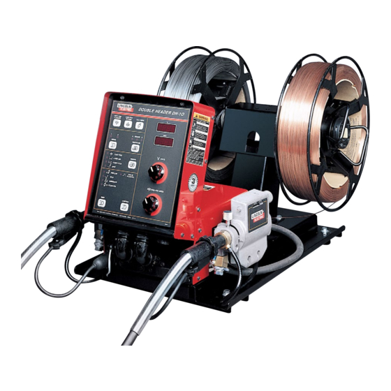
DH-10 HEADS & CONTROLS BOOM MOUNT OR BENCH MODELS
For use with machines having Code Numbers:
DH-10 Control - Boom Mount Code
DH-10 Drive - Boom Mount Codes
DH-10 Boom Package Codes
Standard - Single Head Drive Codes
DH-10 Feeder Double Head - Bench Model Codes
SERVICE MANUAL
SVM143-A
| Issue D ate 99-Mar
© Lincoln Global, Inc. All Rights Reserved.
NOTE: This manual will cover most of the troubleshooting and repair
procedures for the code numbers listed. Some variances may exist when
troubleshooting/repairing later code numbers.
10357, 12247, 12456
10358
10359
(Std.),
(Hi/Std.)
10380, 10495, 10496
10190, 10191
10360
10361
(Std.),
(Hi/Std.)
10517, 10518, 10519
(Std.), and
(Hi/Std.)
Advertisement
Chapters
Table of Contents
Troubleshooting

Subscribe to Our Youtube Channel
Related Manuals for Lincoln Electric 12247


Summary of Contents for Lincoln Electric 12247
- Page 1 Some variances may exist when troubleshooting/repairing later code numbers. DH-10 HEADS & CONTROLS BOOM MOUNT OR BENCH MODELS For use with machines having Code Numbers: 10357, 12247, 12456 DH-10 Control - Boom Mount Code 10358 10359 DH-10 Drive - Boom Mount Codes (Std.),...
-
Page 2: California Proposition 65 Warnings
351040, Miami, Florida 33135 or CSA Standard W117.2-1974. A Free copy of “Arc Welding Safety” booklet E205 is available from the Lincoln Electric Company, 22801 St. Clair Avenue, Cleveland, Ohio 44117-1199. BE SURE THAT ALL INSTALLATION, OPERATION, MAINTENANCE AND REPAIR PROCEDURES ARE PERFORMED ONLY BY QUALIFIED INDIVIDUALS. -
Page 3: Safety
SAFETY ARC RAYS can burn. ELECTRIC SHOCK can 4.a. Use a shield with the proper filter and cover kill. plates to protect your eyes from sparks and 3.a.The electrode and work (or ground) circuits the rays of the arc when welding or observing are electrically “hot”... - Page 4 SAFETY WELDING SPARKS can CYLINDER may explode cause fire or explosion. if damaged. 6.a. Remove fire hazards from the welding area. 7.a. Use only compressed gas cylinders If this is not possible, cover them to prevent containing the correct shielding gas for the the welding sparks from starting a fire.
- Page 5 SAFETY 5. Toujours porter des lunettes de sécurité dans la zone de PRÉCAUTIONS DE SÛRETÉ soudage. Utiliser des lunettes avec écrans lateraux dans les zones où l’on pique le laitier. Pour votre propre protection lire et observer toutes les instruc- tions et les précautions de sûreté...
-
Page 6: Table Of Contents
MASTER TABLE OF CONTENTS FOR ALL SECTIONS Page Safety ........... . . i-iv Installation . - Page 7 SECTION A-1 SECTION A-1 INSTALLATION TABLE OF CONTENTS -INSTALLATION SECTION- Installation ............... . Section A Technical Specifications —...
-
Page 8: Installation
INSTALLATION TECHNICAL SPECIFICATIONS – DH-10 Complete Units or Controls & Heads The K1499-1 or -2 DH-10 consists of a control and a double head 10 series wire drive assembly pre- mounted on a platform with two 2 in. O.D. spindle mountings. Specifications for the units follow: CONTROLS SECTION OF COMPLETE UNITS SPEC.# TYPE... -
Page 9: General Description
Bench and Boom models. Specifications. Bench Models consists of a DH-10 control and a DH Recommended power sources are Lincoln Electric double header wire drive assembly premounted on a Company constant voltage power sources with 42 platform with a dual 2 in. O.D. spindle mounting. -
Page 10: Safety Precautions
INSTALLATION SAFETY PRECAUTIONS Mounting Single Head Wire Drive Unit (K679-1 or -2) WARNING Mount the wire feed unit by means of the insulated mounting bracket attached to the bottom of the gearbox. ELECTRIC SHOCK can kill. Reference L9777 (included with Drive unit) to find the •... -
Page 11: Wire Drive Speed Range Selection
INSTALLATION Connecting Wire Drive Unit to Control Box mum, and also that the force required to pull the wire from the reel into the wire drive unit is kept at a minimum. One head to control cable assembly is required for each head being used;... -
Page 12: Wire Feed Drive Roll Kits
INSTALLATION To remove feedplate: WIRE FEED DRIVE ROLL KITS a. Loosen the clamping collar screw using a NOTE: The maximum rated solid and cored wire 3/16 in. Allen wrench. The clamping collar sizes for each wire drive head and selected drive ratio screw is accessed from the bottom of the is shown on the Specifications in the front of this feedplate. -
Page 13: Gun And Cable Assemblies With Standard Connection
INSTALLATION Single Drive 4-Roll Kits (KP655 and KP656) 5. Insert inner Wire Guide, groove side out, over the two locating pins in the feedplate. 1. Turn OFF welding power source. 6. Install each drive roll by pushing over shaft until it 2. -
Page 14: Gun And Cable Assemblies With Fast-Mate Connection
INSTALLATION Gun Cable Connection with Standard Gun Cable Connection with Fast-Mate Connection Connection 1. Check that the drive rolls, feeder guide tubes and 1. Check that the drive rolls and guide tubes are gun connector guide tube are appropriate for the proper for the electrode size and type being electrode size being used. -
Page 15: Electrical Installation
INSTALLATION GMAW Shielding Gas ELECTRICAL INSTALLATION WARNING WARNING CYLINDER may explode if damaged. ELECTRIC SHOCK can kill. • Keep cylinder upright and chained to • Do not touch electrically live parts support. such as output terminals or internal wiring. • Keep cylinder away from areas where it may be damaged. -
Page 16: Optional Features Installation
A-10 A-10 INSTALLATION K1503 Consists of a 9-conductor control cable with a OPTIONAL FEATURES 14-pin plug and 2/0 (67 mm ) electrode cable with INSTALLATION Twist-Mate™ connector. It is rated at 500 amps, 60% duty cycle and is available in lengths of 10 ft (3 m), K1501, K1502 and K1503 Input Cable Assemblies 17 ft (5 m), 25 ft (7.6 m), 33 ft (10 m) and 50 ft (15 m) and 100 ft (30 m) is also available with a 3/0 (85 mm... - Page 17 A-11 A-11 INSTALLATION Magnum conduit to go between the reel cover and the K590-4 Water Connection Kit (For DH Drive Only). feedplate. Install per the instructions shipped with the kit. One used per gun. Gun Adapters (For DH Wire Drive Heads) K682-2 Water Connection Kit (K679 Single Head Adapts DH heads for desired gun connection Drive Only).
- Page 18 A-12 A-12 INSTALLATION DH-10...
- Page 19 SECTION B-1 SECTION B-1 OPERATION TABLE OF CONTENTS -OPERATION SECTION- Operation ............... . . Section B Safety Precautions .
-
Page 20: Safety Precautions
OPERATION SAFETY PRECAUTIONS Setting the DIP Switches WARNING The DIP switches are each labeled with an “ON” arrow showing the on direction for each of the 8 indi- ELECTRIC SHOCK can kill. vidual switches in each DIP switch (S1 and S2). The functions of these switches are also labeled and set •... -
Page 21: Welding Power Source Selection
OPERATION SINGLE HEADS: Welding Power Source Selection For K1563-1 (LN-10 Boom) with 35-500 IPM (0.89- The DH-10 Control is set up for proper presettable 12.7 m/m) Low Speed Ratio set S2 DIP Switches as weld voltage control by setting S1 DIP switches (1 to follows: 4) as appropriate per the following information for the HEAD 1... -
Page 22: Metric/English Wire Feed Speed Display Selection
OPERATION Pulse Power 500: Metric/English Wire Feed Speed Security Pwr Sources Display Selection The DH-10 Control is set up for Wire Feed Speed dis- play in Metric units (m/min) or English units (IPM) by V300 PRO: setting S1 DIP switch 6 (Labeled “M”): Security Pwr Sources S1 switch 6 OFF = IPM (as shipped) -
Page 23: Low Security Mode Selection
4. Reopening Trigger stops gas flow if, or when, postflow time is over. CONTROL TIMER Low Security Mode Selection THE LINCOLN ELECTRIC COMPANY CLEVELAND, OHIO U.S.A. G3030 The DH-10 Control is set up for Low Security Mode Keypad and Display Description (See “Security Modes”... -
Page 24: Operation Keys
OPERATION Dual procedure settings, including; trigger mode, cold Trigger Mode Selection feed speed, Run-in and weld speed and voltage, timers and acceleration are automatically saved for Trigger Mode Select key - COLD FEED each feeder when power is removed. This feature enables operator to choose TRIGGER does not require batteries and when power is restored... -
Page 25: Display Control Keys
OPERATION Display Control Keys If set below minimum rated speed “---” will show on the WFS display, indicating Run-in speed is set to match weld speed setting. Timer Select key - enables operator to TIMER choose burnback, spot or gas timers, as The Run-in (strike) voltage can be set above or below indicated by the appropriate light. -
Page 26: Dual Procedure Remote Control (K1449-1)
OPERATION To change acceleration hold the Gas Purge Key DUAL PROCEDURE REMOTE closed, then press the Control key. The top (Voltage) CONTROL (K1449-1) display shows “Acc” indicating acceleration setting, 1 thru 5, is displayed on the bottom (Speed) display. When this option is connected to the DH-10 Control Use the speed encoder knob to change setting of 1 Box receptacle, and the Procedure Key selects thru 5. -
Page 27: To Mount 10 To 44 Lb (4.5 To 20 Kg) Spools (12 In/300 Mm Diameter) Or 14 Lb (6 Kg) Innershield Coils (Figure
OPERATION To Mount a 50 to 60 lb (22.7 to 27.2 kg) CAUTION Coil: (Using K1504-1 Coil Reel) (For 50 to 60 Check to be sure the Retaining Spring has fully lb Readi-Reels a K438 Readi-Reel Adapter must be returned to the locking position and has SECURELY used). -
Page 28: Feeding Electrode And Brake Adjustment
MAKING A WELD setting. The optimum drive roll pressure varies with type of 1. Use only a Lincoln Electric recommended con- wire, surface condition, lubrication, and hardness. stant voltage DC power source compatible with Too much pressure could cause “birdnesting”, but too the DH-10 Wire Feeder. -
Page 29: Wire Reel Changing
B-11 B-11 OPERATION 4. Use Control Select and encoder knobs to set WIRE REEL CHANGING desired Weld feed speed and voltage then Run-in speed and voltage to optimize arc starting. (Set for At the end of a coil, remove the last of the old elec- each procedure if using front panel, remote control trode coil from the conductor cable by either pulling it or optional dual procedure switch.) (Refer to... -
Page 30: Grounding Lead Protector
B-12 B-12 OPERATION GROUNDING LEAD PROTECTOR is activated the wire feeder is disabled (the trigger output to the power source is opened up, the motor is stopped, and the gas The frame of the DH-10 Control is grounded to the solenoid is turned off). -
Page 31: Accessories Section
SECTION C-1 SECTION C-1 ACCESSORIES TABLE OF CONTENTS -ACCESSORIES SECTION- Accessories ............... Section C General . -
Page 32: General
ACCESSORIES GENERAL The following is a list of all the accessories that can be used with the DH-10 Dual Head Wire Feeder. A description of each item is given later in the section. TABLE C.1 — DH-10 DUAL HEAD WIRE FEEDER ACCESSORIES. KP1505 Series DRIVE ROLL AND GUIDE TUBE KITS KP1507 Series... - Page 33 ACCESSORIES DRIVE ROLL AND GUIDE TUBE KITS Table C.2 gives a listing of all of the Drive Roll and Guide Tube Kits that are available for the DH-10 Dual Head Wire Feeder. TABLE C.2 — DRIVE ROLL AND GUIDE TUBE KITS. Wire Size 4-Roll 4-Roll...
-
Page 34: Input Cable Assemblies
ACCESSORIES INPUT CABLE ASSEMBLIES K1450-“L” - Extension cables are available in lengths “L” of 12, 16 or 25 ft (3.6, 4.9 or 7.6 m) to match the (One required per DH-10 Control Box.) control to Feeder cable length used. K1501 (Control Cable Only) - Consists of a 9-conduc- K1558-1 - Remote Switch Interface Module, can be tor control cable with a 14-pin control cable plug, with- used with the DH-10, using a G3041-2 (or higher) -
Page 35: Gun Adapters (For Dh Wire Drive Heads
ACCESSORIES Readi-Reel Adapters K497 (With K466-9 requires K1500-2) Magnum 200 GMAW gun and cable assemblies are rated 200 K363P - Adapts Lincoln Readi-Reel coils of electrode amps, 60% duty cycle. (Consult sales specifications 30 lb (14 kg) and 22 lb (10 kg) to a 2 in. (51 mm) spin- for appropriate models.) dle. - Page 36 ACCESSORIES K1556-1 LIGHT DUTY CASTER KIT K1634-1 WIRE REEL ENCLOSURE KIT This option provides 4 casters and all required hard- Provides the necessary parts to cover the wire and ware to mount it to the Power Feed 10. This option is protect if from excessive dirt and contamination.
-
Page 37: Maintenance Section
SECTION D-1 SECTION D-1 MAINTENANCE TABLE OF CONTENTS -MAINTENANCE SECTION- Maintenance ..............Section D Safety Precautions . -
Page 38: Maintenance
MAINTENANCE SAFETY PRECAUTIONS of teeth so they can be reversed for additional life. Drive rolls for 0.023 in. (0.6 mm) through 0.052 in. (1.3 mm) solid electrodes and aluminum sizes have WARNING no teeth, but use two grooves so they also can be ELECTRIC SHOCK can kill. -
Page 39: Periodic Maintenance
MAINTENANCE PERIODIC MAINTENANCE PROCEDURE FOR REMOVING FEEDPLATE FROM WIRE FEEDER Wire Drive Motor and Gearbox 1. Loosen the clamping collar screw using a 3/16 in. Every year inspect the gearbox and coat the gear Allen wrench. The clamping collar screw is teeth with a moly-disulfide filled grease. - Page 40 MAINTENANCE DH-10...
-
Page 41: Theory Of Operation Section
SECTION E-1 SECTION E-1 THEORY OF OPERATION TABLE OF CONTENTS -THEORY OF OPERATION SECTION- Theory of Operation ..............Section E General Description . -
Page 42: General Description
THEORY OF OPERATION FIGURE E.1 — GENERAL DESCRIPTION. SOLENOID SOLENOID TO GUN TRIGGER TO GUN TRIGGER DUAL PROCEDURE DUAL PROCEDURE RIGHT LEFT WIRE DRIVE WIRE WIRE WIRE DRIVE DRIVE RECEPTACLE DRIVE RECEPTACLE MOTOR MOTOR TACH FEEDBACK TACH FEEDBACK INPUT CURRENT SENSING CABLE REED SWITCH CONTROL BOARD... -
Page 43: Theory Of Operation
THEORY OF OPERATION FIGURE E.2 — INPUT RECEPTACLE, CONTROL BOARD AND OPERATOR CONTROLS. SOLENOID SOLENOID TO GUN TRIGGER TO GUN TRIGGER DUAL PROCEDURE DUAL PROCEDURE LEFT RIGHT WIRE WIRE WIRE DRIVE WIRE DRIVE DRIVE DRIVE RECEPTACLE RECEPTACLE MOTOR MOTOR TACH FEEDBACK TACH FEEDBACK INPUT CURRENT SENSING... -
Page 44: Wire Feed Heads And Receptacles
THEORY OF OPERATION FIGURE E.3 — WIRE FEED HEADS AND RECEPTACLES. SOLENOID SOLENOID TO GUN TRIGGER TO GUN TRIGGER DUAL PROCEDURE DUAL PROCEDURE LEFT RIGHT WIRE WIRE DRIVE WIRE DRIVE WIRE DRIVE DRIVE RECEPTACLE RECEPTACLE MOTOR MOTOR TACH FEEDBACK TACH FEEDBACK INPUT CURRENT SENSING CABLE... - Page 45 TROUBLESHOOTING AND REPAIR TABLE OF CONTENTS -TROUBLESHOOTING AND REPAIR SECTION- Troubleshooting and Repair ............Section F How to Use Troubleshooting Guide .
-
Page 46: How To Use Troubleshooting Guide
HOW TO USE TROUBLESHOOTING GUIDE WARNING Service and Repair should only be performed by Lincoln Electric Factory Trained Personnel. Unauthorized repairs performed on this equipment may result in danger to the technician and machine operator and will invalidate your factory warranty. For your safety and to avoid electrical shock, please observe all safety notes and precautions detailed throughout this manual. -
Page 47: Pc Board Troubleshooting Procedures
TROUBLESHOOTING AND REPAIR PC BOARD TROUBLESHOOTING PROCEDURES PC board can be WARNING damaged by static electricity. ELECTRIC SHOCK can kill. - Remove your body’s static charge before ATTENTION Have an electrician install opening the static- Static-Sensitive and service this equipment. shielding bag. -
Page 48: Troubleshooting And Repair
TROUBLESHOOTING AND REPAIR 4. Test the machine to determine if the fail- connections in the control wiring har- ure symptom has been corrected by the ness, junction blocks, and terminal replacement PC board. strips. NOTE: It is desirable to have a spare b. -
Page 49: Troubleshooting Guide
Test . CAUTION If for any reason you do not understand the test procedures or are unable to perform the tests/repairs safely, contact the Lincoln Electric Service Department for technical troubleshooting assistance before you proceed. Call 216-383-2531 or 1-888-935-3877. -----------------------------------------------------------------------------------------------------------------------------... - Page 50 CAUTION If for any reason you do not understand the test procedures or are unable to perform the tests/repairs safely, contact the Lincoln Electric Service Department for technical troubleshooting assistance before you proceed. Call 216-383-2531 or 1-888-935-3877. -----------------------------------------------------------------------------------------------------------------------------...
- Page 51 (zero ohms) to the work piece. CAUTION If for any reason you do not understand the test procedures or are unable to perform the tests/repairs safely, contact the Lincoln Electric Service Department for technical troubleshooting assistance before you proceed. Call 216-383-2531 or 1-888-935-3877. -----------------------------------------------------------------------------------------------------------------------------...
- Page 52 CAUTION If for any reason you do not understand the test procedures or are unable to perform the tests/repairs safely, contact the Lincoln Electric Service Department for technical troubleshooting assistance before you proceed. Call 216-383-2531 or 1-888-935-3877. -----------------------------------------------------------------------------------------------------------------------------...
- Page 53 (Plug J2) See the Wiring Diagram. CAUTION If for any reason you do not understand the test procedures or are unable to perform the tests/repairs safely, contact the Lincoln Electric Service Department for technical troubleshooting assistance before you proceed. Call 216-383-2531 or 1-888-935-3877. -----------------------------------------------------------------------------------------------------------------------------...
- Page 54 Head Selection . CAUTION If for any reason you do not understand the test procedures or are unable to perform the tests/repairs safely, contact the Lincoln Electric Service Department for technical troubleshooting assistance before you proceed. Call 216-383-2531 or 1-888-935-3877.
- Page 55 See the Wiring Diagram. CAUTION If for any reason you do not understand the test procedures or are unable to perform the tests/repairs safely, contact the Lincoln Electric Service Department for technical troubleshooting assistance before you proceed. Call 216-383-2531 or 1-888-935-3877.
- Page 56 2. The control board may be faulty. CAUTION If for any reason you do not understand the test procedures or are unable to perform the tests/repairs safely, contact the Lincoln Electric Service Department for technical troubleshooting assistance before you proceed. Call 216-383-2531 or 1-888-935-3877. -----------------------------------------------------------------------------------------------------------------------------...
- Page 57 3. The control board may be faulty. CAUTION If for any reason you do not understand the test procedures or are unable to perform the tests/repairs safely, contact the Lincoln Electric Service Department for technical troubleshooting assistance before you proceed. Call 216-383-2531 or 1-888-935-3877.
- Page 58 CAUTION If for any reason you do not understand the test procedures or are unable to perform the tests/repairs safely, contact the Lincoln Electric Service Department for technical troubleshooting assistance before you proceed. Call 216-383-2531 or 1-888-935-3877. -----------------------------------------------------------------------------------------------------------------------------...
- Page 59 5. The power source may be faulty. CAUTION If for any reason you do not understand the test procedures or are unable to perform the tests/repairs safely, contact the Lincoln Electric Service Department for technical troubleshooting assistance before you proceed. Call 216-383-2531 or 1-888-935-3877. -----------------------------------------------------------------------------------------------------------------------------...
- Page 60 F-16 F-16 NOTES DH-10...
-
Page 61: Test Procedures
WIRE DRIVE MOTOR TEST WARNING Service and repair should only be performed by Lincoln Electric factory trained personnel. Unauthorized repairs performed on this equipment may result in dan- ger to the technician or machine operator and will invalidate your factory warran- ty. -
Page 62: Test Procedure
F-18 F-18 TROUBLESHOOTING AND REPAIR WIRE DRIVE MOTOR TEST (continued) FIGURE F.1 — WIRE DRIVE MOTOR TEST. (+)WHITE LEAD (-)BLACK LEAD DRIVE MOTOR TEST PROCEDURE 5. If the correct voltages are NOT present at the armature motor leads, check the associated leads and plugs for loose or 1. -
Page 63: Tach Adjustment And Feedback Test
TACH ADJUSTMENT AND FEEDBACK TEST WARNING Service and repair should only be performed by Lincoln Electric factory trained personnel. Unauthorized repairs performed on this equipment may result in dan- ger to the technician or machine operator and will invalidate your factory war- ranty. - Page 64 F-20 F-20 TROUBLESHOOTING AND REPAIR TACH ADJUSTMENT AND FEEDBACK TEST (continued) FIGURE F.2 — TACH FEEDBACK TEST. #500 BLACK #555 BLUE #512 HALL EFFECT DEVICE (TACH) TEST PROCEDURE the control board or associated leads or plugs may be faulty. See the Wiring Diagram.
- Page 65 F-21 F-21 TROUBLESHOOTING AND REPAIR TACH ADJUSTMENT AND FEEDBACK TEST (continued) TACH ADJUSTMENT 3. Using the 9/16 in. wrench loosen the locking nut. PROCEDURE 4. Gently screw the hall effect module into Proper positioning of the module is critical the mounting plate until it just touches to the proper operation the DH-10 wire and stops against the rotating part feeder.
- Page 66 Return to Section TOC Return to Section TOC Return to Section TOC Return to Section TOC Return to Master TOC Return to Master TOC Return to Master TOC Return to Master TOC...
-
Page 67: Keypad Resistance Test
KEYPAD RESISTANCE TEST WARNING Service and repair should only be performed by Lincoln Electric factory trained personnel. Unauthorized repairs performed on this equipment may result in dan- ger to the technician or machine operator and will invalidate your factory war- ranty. - Page 68 F-24 F-24 TROUBLESHOOTING AND REPAIR KEYPAD RESISTANCE TEST (continued) FIGURE F.3 — KEYPAD RESISTANCE TEST. DISPLAY BOARD TEST PROCEDURE 6. Check the keypad resistances referenc- ing Figure F.3 and Table F.1 . 1. Remove input power to the DH-10 unit. 7.
- Page 69 F-25 F-25 TROUBLESHOOTING AND REPAIR KEYPAD RESISTANCE TEST (continued) NOTE: There should not be continuity between pins until a key is pressed on the keypad. TABLE F.1 — KEYPAD RESISTANCE TEST. MAXIMUM TEST POINTS ALLOWABLE RESISTANCE FROM PIN TO PIN KEY PRESSED (TYPICAL RESISTANCE) 1J10...
- Page 70 Return to Section TOC Return to Section TOC Return to Section TOC Return to Section TOC Return to Master TOC Return to Master TOC Return to Master TOC Return to Master TOC...
-
Page 71: Encoder Pc Board Test
ENCODER PC BOARD TEST WARNING Service and repair should only be performed by Lincoln Electric factory trained personnel. Unauthorized repairs performed on this equipment may result in dan- ger to the technician or machine operator and will invalidate your factory war- ranty. - Page 72 F-28 F-28 TROUBLESHOOTING AND REPAIR ENCODER PC BOARD TEST (continued) FIGURE F.4 — ENCODER PC BOARD TEST. #500 #526 #516 #527 #517 #505 ENCODER PC BOARDS TEST PROCEDURE 7. While slowly rotating the Volts control check for a “pulsing” 0 to 5 VDC signal from 8J2 (lead #516) to 6J2 (lead 1.
-
Page 73: Gas Solenoid Test
GAS SOLENOID TEST WARNING Service and repair should only be performed by Lincoln Electric factory trained personnel. Unauthorized repairs performed on this equipment may result in dan- ger to the technician or machine operator and will invalidate your factory war- ranty. - Page 74 F-30 F-30 TROUBLESHOOTING AND REPAIR GAS SOLENOID TEST (continued) FIGURE F.5 — GAS SOLENOID TEST. GAS SOLENOID LEADS SOLENOID NOTE: WIRE FEEDER SHOWN WITH DRIVE MOTOR ASSEMBLY REMOVED FOR CLARITY TEST PROCEDURE 6. If the 10 VDC is missing or low, check the leads and connections between the solenoid and the control board.
-
Page 75: Component Replacement Procedures
DISPLAY PC BOARD REMOVAL AND REPLACEMENT WARNING Service and repair should only be performed by Lincoln Electric factory trained personnel. Unauthorized repairs performed on this equipment may result in dan- ger to the technician or machine operator and will invalidate your factory war- ranty. -
Page 76: Removal Procedure
F-32 F-32 TROUBLESHOOTING AND REPAIR DISPLAY PC BOARD REMOVAL AND REPLACEMENT (continued) FIGURE F.6 — DISPLAY PC BOARD REMOVAL AND REPLACEMENT. DISPLAY PC BOARD MOUNTING REMOVAL PROCEDURE REPLACEMENT PROCEDURE 1. Remove input power to the DH-10 unit. 1. Install plug J10 into the new display board. -
Page 77: Gas Solenoid Removal And Replacement
GAS SOLENOID REMOVAL AND REPLACEMENT WARNING Service and repair should only be performed by Lincoln Electric factory trained personnel. Unauthorized repairs performed on this equipment may result in dan- ger to the technician or machine operator and will invalidate your factory war- ranty. - Page 78 F-34 F-34 TROUBLESHOOTING AND REPAIR GAS SOLENOID REMOVAL AND REPLACEMENT (continued) FIGURE F.7 — GAS SOLENOID REMOVAL AND REPLACEMENT. SOLENOIDS CLAMPS MOUNT HOSES NOTE: WIRE FEEDER SHOWN WITH DRIVE MOTOR ASSEMBLY REMOVED FOR CLARITY PROCEDURE 7. Remove the solenoid assembly from the DH-10 unit.
-
Page 79: Encoder Pc Board Removal And Replacement
ENCODER PC BOARD REMOVAL AND REPLACEMENT WARNING Service and repair should only be performed by Lincoln Electric factory trained personnel. Unauthorized repairs performed on this equipment may result in dan- ger to the technician or machine operator and will invalidate your factory war- ranty. - Page 80 F-36 F-36 TROUBLESHOOTING AND REPAIR ENCODER PC BOARD REMOVAL AND REPLACEMENT (continued) FIGURE F.8 — ENCODER PC BOARD REMOVAL AND REPLACEMENT. ENCODER PC BOARD WASHER FELT WASHER SPACER ALLEN KNOB SCREW PROCEDURE 6. Carefully remove the PC board from the front panel. 1.
-
Page 81: Wire Drive Motor And Gear Box Removal And Replacement
WIRE DRIVE MOTOR AND GEAR BOX REMOVAL AND REPLACEMENT WARNING Service and repair should only be performed by Lincoln Electric factory trained personnel. Unauthorized repairs performed on this equipment may result in dan- ger to the technician or machine operator and will invalidate your factory war- ranty. - Page 82 F-38 F-38 TROUBLESHOOTING AND REPAIR WIRE DRIVE MOTOR AND GEAR BOX REMOVAL AND REPLACEMENT (continued) FIGURE F.9 — WIRE FEED ASSEMBLY REMOVAL. MOTOR TACH ARMATURE LEADS LEADS CAP SCREW LOCK WASHER 3/4 in. NUT FLATWASHER GAS HOSE FITTING PROCEDURE 7. Disconnect the motor armature leads. 8.
- Page 83 F-39 F-39 TROUBLESHOOTING AND REPAIR WIRE DRIVE MOTOR AND GEAR BOX REMOVAL AND REPLACEMENT (continued) FIGURE F.10 — DRIVE MOTOR AND WIRE DRIVE ASSEMBLY REMOVAL. DRIVE MOTOR GEAR BOX INSPECTION COVER CONDUCTOR BLOCK GEAR BOX LEAD WIRE DRIVE ASSEMBLY ALLEN SCREWS TO REMOVE THE DRIVE TO REMOVE THE WIRE DRIVE...
-
Page 84: Replacement Procedures
F-40 F-40 TROUBLESHOOTING AND REPAIR WIRE DRIVE MOTOR AND GEAR BOX REMOVAL AND REPLACEMENT (continued) REPLACEMENT PROCEDURES 8. Place the entire assembly into the DH-10 unit. Align the mounting holes with wire feeder base. 1. Carefully slide the wire drive assembly and gear box together. -
Page 85: Retest After Repair
F-41 F-41 TROUBLESHOOTING AND REPAIR RETEST AFTER REPAIR If a failed test indicates that any mechanical Check the Feeder selection and Procedure part which could affect the machine's elec- keys for proper operation. trical characteristics must be replaced, or if any electrical components are repaired or 1. - Page 86 F-42 F-42 NOTES DH-10...
- Page 87 Please include the machine’s code number and how the problem was resolved. Thank You, Technical Services Group Lincoln Electric Co. 22801 ST. Clair Ave. Cleveland, Ohio 44117-1199 FAX 216-481-2309 SVM Number ___________________________...
- Page 88 ELECTRICAL DIAGRAMS TABLE OF CONTENTS ELECTRICAL DIAGRAMS SECTION Electrical Diagrams Section...................Section G Wiring Diagram (Control) (L10218)....................G-2 Wiring Diagram (Wire Drive) (M17871) ..................G-3 Control Board Schmatic (Sheet 1) (G3040-1) ................G-4 Control Board Schmatic (Sheet 2) (G3040-2) ................G-5 Display Board Schematic (L10138) .....................G-6 Encoder Board Schematic (S22066) ...................G-7 Control Board Layout (G3041-2) ....................G-8 Display Board Layout (L10139-1) ....................G-9...
- Page 89 ELECTRICAL DIAGRAMS Wiring Diagram (Control) (L10218) WIRING DIAGRAM (DH-10 CONTROL) PIN NUMBERING SEQUENCE CONNECTOR CAVITY NUMBERING SEQUENCE J19*** CASE GROUNDING GROUNDING LEAD COLOR CODING STUD LEAD B - BLACK PIN 1 PIN 1 PROTECTOR R - RED W - WHITE P19*** U - BLUE CONTROL P.C BOARD...
-
Page 90: Electrical Diagrams
ELECTRICAL DIAGRAMS Wiring Diagram (Wire Drive) (M17871) NOTE: This diagram is for reference only. It may not be accurate for all machines covered by this manual. The wiring diagram specific to your code is pasted inside one of the enclosure panels of your machine. DH-10 M17871 11-21-97J... -
Page 91: Control Board Schmatic (Sheet 1) (G3040-1
5-2-97 able from Lincoln Electric. This information is provided for reference only. Lincoln Electric discourages board level troubleshooting and repair since it may compromise the quality of the design and may result in danger to the Machine Operator or Technician. Improper PC board repairs could result in damage to the machine. - Page 92 NOTE: Lincoln Electric assumes no responsibility for liablilities resulting from board level troubleshooting. PC Board repairs will invalidate your factory warranty. Individual Printed Circuit Board Components are not avail- 5-2-97 able from Lincoln Electric. This information is provided for reference only. Lincoln Electric discourages board level troubleshooting and repair since it may compromise the quality of the design and may result in DH-10...
-
Page 93: Display Board Schematic (L10138
NOTE: Lincoln Electric assumes no responsibility for liablilities resulting from board level troubleshooting. PC Board repairs will invalidate your factory warranty. Individual Printed Circuit Board Components are not avail- 5-2-97 able from Lincoln Electric. This information is provided for reference only. Lincoln Electric discourages board level troubleshooting and repair since it may compromise the quality of the design and may result in DH-10... -
Page 94: Encoder Board Schematic (S22066
ELECTRICAL DIAGRAMS Encoder Board Schematic (S22066) DH-10 S22066 4-7-95... -
Page 95: Electrical Diagrams
NOTE: Lincoln Electric assumes no responsibility for liablilities resulting from board level troubleshooting. PC Board repairs will invalidate your factory warranty. Individual Printed Circuit Board Components are not avail- 2-20-98M able from Lincoln Electric. This information is provided for reference only. Lincoln Electric discourages board level troubleshooting and repair since it may compromise the quality of the design and may result in DH-10... -
Page 96: Display Board Layout (L10139-1
ELECTRICAL DIAGRAMS Display Board Layout (L10139-1) DH-10 L10139-1 5-2-97... -
Page 97: Encoder Board Layout (M17797-1
Individual Printed Circuit Board Components are not available from Lincoln Electric. This information is provided for reference only. Lincoln Electric discourages board level troubleshooting and repair since it may compromise the quality of the design and may result in danger to the Machine Operator or Technician. Improper PC board repairs could result in damage to the machine. - Page 98 NOTES DH-10...
Need help?
Do you have a question about the 12247 and is the answer not in the manual?
Questions and answers