
Related Manuals for Alfa Laval CF100


Summary of Contents for Alfa Laval CF100
- Page 1 Alfa Laval Separation System CF100 Installation and Operating Lit. Code 200007093-2-EN-GB Manual No. 9662058512 instructions BRITISH ENGLISH...
- Page 2 © Alfa Laval Corporate AB 2022-10 This document and its contents are subject to copyrights and other intellectual property rights owned by Alfa Laval Corporate AB. No part of this document may be copied, re-produced or transmitted in any form or by any means, or for any purpose, without Alfa Laval Corporate AB’s prior express written permission. Information and services provided in this document are made as a benefit and service to the user, and no representations or warranties are made about the accuracy or suitability of this information and these services for any purpose.
-
Page 3: Table Of Contents
Contents 1 Introduction and General Information ............5 Scope of this book.....................5 Safety Instructions.....................6 General description of Alfa Laval Separation System..........11 System description....................11 2 Installation, Maintenance and Lifting Instructions ......15 Unpacking and Initial Inspection of the Separator...........15 Lifting instructions....................18... - Page 4 6.10 Discharge performance and Bowl closing supervision..........48 6.11 Output test.......................49 7 Alarm Management ....................51 Alarm acknowledgement..................51 Alarm activation diagram..................53 8 Installation and Setup information .............. 55 Passwords.......................55 VFD Parameters......................56 Speed relay......................60 Flow meters......................61 9 Ordering Spare parts ................... 63 Spare parts......................63 Alfa Laval Service....................63...
-
Page 5: Introduction And General Information
1 Introduction and General Information 1.1 Scope of this book The Installation and Operating instructions given in this manual are designed for the Alfa Laval separation system with valve arrangement and Siemens PLC automation. In this manual you will find: •... -
Page 6: Safety Instructions
Alfa Laval will not be responsible for any breakdown of the equipment caused by the owner’s failure to follow the instructions given in this documentation. This documen- tation describes the authorized way to use the separator system. -
Page 7: Installation
Repairs: unscheduled break-down of a component, often causing the system to stop. Damaged components shall be replaced or repaired. • Stock of recommended spare parts: Alfa Laval recommends keeping a stock of spare parts facilitating preventive maintenance and reducing the system down time in case of unplanned bread downs. - Page 8 Safety Stop • After a safety stop the cause of the fault must be identified. If all parts have been checked and the cause remains unclear, contact Alfa Laval for advice. Vibration • If the separator begins to vibrate excessively during operation, stop it immediately by pushing the emergency stop button and evacuate the room.
- Page 9 Introduction and General Information 1 Hazards Hazardous Area • Cleaning, maintenance and repair work may be done only at nonexplosive atmos- phere. • The separator may be hazardous when passing its critical speeds during the run- down. • For reasons of safety, only tools made of non-sparking material may be used when performing work in hazardous area.
- Page 10 1 Introduction and General Information Corrosion Hazard • Always handle cleaning liquids, lye and acid with great care and in accordance with separate instructions for those fluids. • When using chemical cleaning agents and lubricants, make sure you follow the general rules and suppliers recommendation regarding ventilation, personnel pro- tection etc.
-
Page 11: General Description Of Alfa Laval Separation System
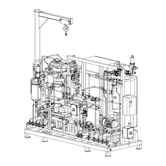
Introduction and General Information 1 1.3 General description of Alfa Laval Separation System The separation system is designed for biotech applications where aseptic conditions and containment might be necessary. It is a sterilizable system with product and utility line, cyclone, valve arrangement, and automation with control panel and CIP panel. - Page 12 1 Introduction and General Information Process liquid module The process liquid components are used for flow control through the separator and steam supply. There is an inlet for product liquid / CIP supply (201.1), and a steam inlet (452). There is also an outlet for the centrifugate / CIP return (220.1).
- Page 13 Introduction and General Information 1 The flushing liquid is used to prevent solids built-up in the cyclone, above and under the bowl and in the air recirculation tube. The sealing liquid cools and lubricates the axial seal of the separator. The cooling liquid is used to cool the separator frame.
- Page 14 1 Introduction and General Information 200007093-2-EN-GB...
-
Page 15: Installation, Maintenance And Lifting Instructions
2 Installation, Maintenance and Lifting Instructions NOTE For installation and maintenance of the separator, refer to the instructions in the separator documentation. NOTE For installation and maintenance of equipment, refer to the supplier documentation provided in section 4 and 5 of the turnover package. 2.1 Unpacking and Initial Inspection of the Separator THIS WAY UP Position: Near left hand upper corner... - Page 16 • If during the inspection of the delivered components there are found damaged or missing items, it shall be reported to Alfa Laval immediately after the delivery has taken place. • Alfa Laval can instruct how to repair possible damages or how to replace missing items.
- Page 17 Installation, Maintenance and Lifting Instructions 2 Storage Before storing a separator that has been in operation, make sure to drain any parts containing water, such as Operating water module (if any), Operating water system and Cooling jackets. Upon arrival to the store, check all components and keep them: •...
-
Page 18: Lifting Instructions
2.2 Lifting instructions NOTE Always refer to the layout drawing and lifting drawing for overall dimensions, weight and connection points (as per scope of supply from Alfa Laval). NOTE When lifting a separator, always follow the instructions from the separator’s installation manual. -
Page 19: Mechanical Installation And Maintenance
2.3 Mechanical installation and maintenance The separation system should be placed in such a way that suitable space for maintenance and repair is obtained. Always contact local Alfa Laval representative for a guidance on the installation details. Mechanical installation work should always be performed by authorized personnel and according to local legislation. -
Page 20: Electrical Installation And Maintenance
2 Installation, Maintenance and Lifting Instructions 2.4 Electrical installation and maintenance Always refer to the electrical drawings provided with the system before carrying out electrical installation. Electrical installation work must always be performed by authorized electricians and personnel, and should be done according to local legislation. The dimensions of the control cabinet and cables can be found in the electrical drawing for the system. -
Page 21: Cleaning
Clean all parts of the remains of product and contamination. Do not scratch or damage parts during cleaning. Use only Alfa Laval recommended CIP liquids. The plant operator is responsible for selecting the cleaning material and performing the procedure. -
Page 22: Installation Of Auxiliary Equipment
2 Installation, Maintenance and Lifting Instructions 2.6 Installation of Auxiliary Equipment Below are the general check points of installation of auxiliary equipment such as valve modules and electric/pneumatic units. • Fasten valve modules such as process liquid module or service liquid unit with bolts of high strength material to the foundation. -
Page 23: Start-Up And Commissioning
3 Start-Up and Commissioning 3.1 Before Start-Up and Commissioning Before commissioning or start-up of the system can be initiated, the following two conditions should be fulfilled: • OWMC service to be done before separator commissioning according to instructions in the “Service & maintenance manual” of separator. •... -
Page 24: Completion And Start-Up
3 Start-Up and Commissioning 3.2 Completion and Start-Up • For general start-up of the module please refer to the “Operation Instructions” of the documentation and check below points: • Check that all pipe connections have been made according to the supplied drawings and documentation. -
Page 25: Description Of Operating Conditions
4 Description of operating conditions 4.1 MAIN SEQUENCE The software has been specially developed to operate the system to always provide the best possible performance, flexibility and a safe operation. The control program has many features and the main operating modes and options are described below. -
Page 26: Sterilization
4 Description of operating conditions NOTE A safety check is run through automatically when entering STAND STILL. This test must be passed successfully in order to receive start permission for the separator 4.4 STERILIZATION STERILIZATION means that semi-automatic program to sterilize the separation system with steam is carried out. -
Page 27: Production
Description of operating conditions 4 In STANDBY WET it is possible to initiate a solid discharge manually by selecting DISCHARGE. It is also possible to initiate discharges automatically. (Refer to Discharge in sub sequence section of the SDS). 4.8 PRODUCTION PRODUCTION means that the separator is running at full selected speed. - Page 28 4 Description of operating conditions 200007093-2-EN-GB...
-
Page 29: Operating Routine
5 Operating routine NOTE Make sure that the separator is assembled correctly. Always consult the Installation manual of the separator. NOTE Make sure that all electrical and liquid connections are made correctly according to the electrical drawing and the connection list, and that all couplings are tightened. NOTE Make sure that the separator control system is activated. -
Page 30: Pressure Test
5 Operating routine 5.2 PRESSURE TEST PRESSURE TEST can be selected from STAND STILL. Select Pressure test on the operator panel. An automatic sequence is run through to check that the system is ight. Automatic return to STAND STILL. 200007093-2-EN-GB... -
Page 31: Sterilization
Operating routine 5 5.3 STERILIZATION STERILIZATION can be selected from STANDSTILL. Make sure that steam is available. Select STERILIZATION on the operator panel. It is possible to interrupt STERILIZATION at any time by selecting STOP. 200007093-2-EN-GB... -
Page 32: System Drain
5 Operating routine 5.4 SYSTEM DRAIN SYSTEM DRAIN can be selected in STAND STILL. Make sure that all liquid supplies to the system are closed. Select SYSTEM DRAIN on operator panel. Most automatic valves will be open, and the separator motor starts once up to a certain speed set point. -
Page 33: Start
Operating routine 5 5.5 START START can be selected from STAND STILL or STOP. Make sure that cooling liquid and purified water is available. Check that no alarm override functions are activated. If necessary, sterilize the separator. Select START on the operator panel. The system indicates STARTING and the power to the separator motor is on and it begins to run. -
Page 34: Standby
5 Operating routine 5.6 STANDBY There are two sub modes of the STANDBY mode: STANDBY WET (with water feed) and STANDBY DRY (without liquid feed). In STANDBY WET automatic discharges are possible. In both sub modes it is possible to initiate a solids discharge manually: Select Discharge on the operator panel. -
Page 35: Production
Operating routine 5 5.7 PRODUCTION PRODUCTION can be selected from STANDBY DRY or STANDBY WET. The feed could be controlled by FCV220–1 (P215=1) or feed pump (P215=0). Select PRODUCTION on the operator panel. The separator is fed with product from the feed inlet line (201.1) The accumulated solids in the bowl periphery is discharged at certain intervals. -
Page 36: Cip (Cleaning In Place)
5 Operating routine 5.8 CIP (Cleaning in place) CIP can be selected from STANDBY DRY or STANDBY WET. Select CIP on the operator panel. CIP is indicated on the display. The discharge interval to the next discharge is counted down. The separator is fed with cleaning liquid from the feed inlet line (201.1). -
Page 37: Emergency Stop
Operating routine 5 5.9 EMERGENCY STOP If you push the emergency stop button the system will switch to EMERGENCY STOP mode. This means that the control power for all motor contactors is deactivated. All other equipment is controlled as in normal STOP mode. The alarm A42 Emergency stop activated is given. - Page 38 5 Operating routine 200007093-2-EN-GB...
-
Page 39: The Control System And Function Description
6 The Control system and Function description In the following section the operator interface and the control and supervision functions of the system are described. 6.1 Control panel The control cabinet contains Siemens PLC, CPU, communication processor, circuit breakers, signal converters, and interface relay. The control panel door consists of: •... -
Page 40: Operator Interface And Function Description
6 The Control system and Function description 6.2 Operator interface and function description NOTE To be able to use all functions of the operator interface the operator has to log in on the right authority level. Read more about different authority levels in the Log In section of the SDS. -
Page 41: Process Screen
The Control system and Function description 6 6.3 Process screen The top header of the screen contains: • Information about the logged in user • Current operation mode • Time/date The second row contains: • Functionality to change or select HMI screen according to the Operating interface diagram. -
Page 42: Cip Process Screen
6 The Control system and Function description 6.4 CIP Process screen To see the process overview of the CIP module, choose the tab named “Process CIP” on the upper part of the screen. CIP screen has the same function buttons at the bottom of the screen as the separator process screen. Controller screens can be accessed for the CIP pump and CIP temperature control valve, by touching the respective icons on the screen. -
Page 43: Parameters
The Control system and Function description 6 6.5 Parameters Parameter settings gives functionality to set different set points within minimum and maximum allowed values for each parameter. The process parameters shows all process parameters including unit, minimum and maximum values. The system parameters shows all system parameters including unit, minimum and maximum values Some of the parameter settings are system specific and should not be... -
Page 44: Trend
6 The Control system and Function description 6.6 Trend On the Trend screen, and on certain screens the where the Show Trend button is available and clicked, diagrams like this be displayed. With the function buttons under the diagram it is possible to look at he logged data for the last 15 minutes;... -
Page 45: Discharge Logic
The Control system and Function description 6 6.7 Discharge logic This menu can be used to change the discharge type PRODUCTION only) and adjust the discharge interval settings. The appearance of this menu changes depending on the actual peration mode. To change a setting, the system should be in the corresponding operation mode. -
Page 46: Current Log
6 The Control system and Function description 6.8 Current log This screen indicates the ten last current peaks during a discharge cycle. The size of current increase after the latest discharge can be inspected. By selecting Show Trend, a current trend diagram for the current log can be displayed. -
Page 47: System
The Control system and Function description 6 6.9 System The system screen displays system information such as program number and version, running hours and discharge counter for the separator. In this screen it is possible to access the alarm history (see also Alarm management) and the I/O displays, also to clear the counters for running hours and discharges. -
Page 48: Discharge Performance And Bowl Closing Supervision
6 The Control system and Function description 6.10 Discharge performance and Bowl closing supervision A current monitor for supervision of the discharge performance and that the bowl is not leaking is included in the control equipment. The power consumption characteristics of the separator motor changes when sediment is discharged from the bowl periphery. -
Page 49: Output Test
The Control system and Function description 6 6.11 Output test The output test makes it possible to change the status of most of the system output signals one at a time for testing purpose (see the I/O-list in technical documentation). Select manual mode on the screen. - Page 50 6 The Control system and Function description 200007093-2-EN-GB...
-
Page 51: Alarm Management
7 Alarm Management The separator and the auxiliary equipment are supervised by the control system. If one of the system components does not function as assigned, an alarm is given and in some cases action is required. 7.1 Alarm acknowledgement New alarm You are alerted to the new alarm by the alarm lamp flashing on the control panel, and an optical or acoustical signal (if connected, normally supplied by... - Page 52 7 Alarm Management Alarm history Alarm history screen displays the latest 100 alarms. Selecting Alarm History on the SYSTEM screen gives access to the alarm history list. For each alarm, the status will be indicated: • I means that the alarm is active, (I = Incoming) •...
-
Page 53: Alarm Activation Diagram
Alarm Management 7 7.2 Alarm activation diagram How to read the Alarm activation diagram The Alarm activation diagram in the SDS of technical documentation lists all supervised functions in the system and gives an explanation of the different alarm codes used. Furthermore, for each supervised function the appropriate alarm interlock in each operation mode is shown. - Page 54 7 Alarm Management 200007093-2-EN-GB...
-
Page 55: Installation And Setup Information
8 Installation and Setup information 8.1 Passwords User Password admin system 2760 process 200007093-2-EN-GB... -
Page 56: Vfd Parameters
8 Installation and Setup information 8.2 VFD Parameters Separator Number Parameter name Default Adjusted value Notes 3-00 Reference range [1]-MAX- +MAX [0] MIN-MAX 3-03 Maximum reference 1500 3050 3-04 Reference function External/preset 3-41 Ramp 1 Ramp up time 3-42 Ramp 1 Ramp down time works with 4-13 Motor speed high limit... - Page 57 Installation and Setup information 8 P201-1 Number Parameter name Default Adjusted value Notes P402(05) Analog input adjustment P403(05) Analog input adjustment P434(01) Digital out function Inverter ready P434(02) Digital out function Inverter is working P301-1 Number Parameter name Default Adjusted value Notes 3-00 Reference range...
- Page 58 8 Installation and Setup information 1. Set parameter 5-12 to "no operation" 2. Set parameter 1-29 to "AMA complete", then follow instructions on screen 3. When "AMA" is finished, set parameter 5-12 to "coast inverse" P320-1 Number Parameter name Default Adjusted value Notes 3-00...
- Page 59 Installation and Setup information 8 P322-1 and P323-1 1st level 2nd level 3rd level 4th level 5th level Xth level Settings Operating mode Analogue Standard Settings 4...20 mA Metering Metering profile Settings Standard Inputs/outputs Relay 0 Relay1 type Warning+error Relay 1 polarity Normally closed (NC) Settings...
-
Page 60: Speed Relay
8 Installation and Setup information 8.3 Speed relay Table 1: Pepperl & Fuchs KFD2-UFC.1.D Number Parameter name Default Adjusted value Notes Unit Unit Lead brakage/short circuit Input detection Pulses/unit Output Relay 1 Min/Max Trip 9700 rpm Hysteresis 100 rpm Relay 1 Min/Max Trip 9700 rpm... -
Page 61: Flow Meters
Installation and Setup information 8 8.4 Flow meters FIT321–1 Parameter Adjusted value Display volume flow Range 0–5000 l/h Analog output 4-20 mA Freq. output 1 pulse/litre FIT201–1 Parameter Adjusted value Display volume flow Range 0–5000 l/h Analog output 4-20 mA Freq. - Page 62 8 Installation and Setup information 200007093-2-EN-GB...
-
Page 63: Ordering Spare Parts
9.2 Alfa Laval Service Alfa Laval is represented in all major ports of the world. Do not hesitate to contact your local Alfa Laval representative with any questions, problems or requirement of spare parts for Alfa Laval equipment. When asking for assistance, always state installation reference and year (see name plate on electrical panels).
Need help?
Do you have a question about the CF100 and is the answer not in the manual?
Questions and answers