
Related Manuals for Alfa Laval CPM-I-D60


Summary of Contents for Alfa Laval CPM-I-D60
- Page 1 Instruction Manual CPM-I-D60 Constant-Pressure Modulating Inlet Valve ESE01834-EN5 2022-11 Original manual...
-
Page 3: Table Of Contents
5.1. General maintenance ................5.2. Dismantling ..................5.3. Assembly ..................6. Technical data ................6.1. Technical data ..................6.2. Selection / Pressure drop - capacity diagram ..........7. Parts lists and service kit ..............7.1. CPM-I-D60 ..................7.2. Booster .................... -
Page 4: Declarations Of Conformity
EU Declaration Declaration of of of Conformity Conformity Declaration Conformity The Designated Company Alfa Laval Kolding A/S, Albuen 31, DK-6000 Kolding, Denmark, +45 79 32 22 00 Company name, address and phone number Hereby declare that Valve Designation CPM-I-D60 Type... - Page 5 UK Declaration Declaration of of of Conformity Conformity Declaration Conformity The Designated Company Alfa Laval Kolding A/S, Albuen 31, DK-6000 Kolding, Denmark, +45 79 32 22 00 Company name, address and phone number Hereby declare that Valve Designation CPM-I-D60 Type...
-
Page 6: Safety
2 Safety Unsafe practices and other important information are emphasized in this manual. Warnings are emphasized by means of special signs. 2.1 Important information Always Always Always r r r ead ead the the manual manual befor manual befor before e e using using using the the valve! -
Page 7: Safety Precautions
2 Safety Unsafe practices and other important information are emphasized in this manual. Warnings are emphasized by means of special signs. 2.3 Safety precautions Installation Installation Installation Always read the technical data thoroughly (See chapter 6 Technical data) Always Always Always release compressed air after use. -
Page 8: Installation
Check Check delivery: CAUTION CAUTION CAUTION 1. Complete valve. 2. Delivery note. Alfa Laval cannot be held responsible for incorrect unpacking. 3. Instruction manual. Step Step 2 2 2 Step * * * = = = Remove Remove Remove packing... -
Page 9: General Installation
Never Never touch the valve top if compressed air is supplied to the valve. CAUTION CAUTION CAUTION Alfa Laval cannot be held responsible for incorrect installation. Step Step Step 2 2 2 Ensure that the flow direction is correct. A = Inlet... - Page 10 3 Installation Study the instructions carefully and pay special attention to the warnings! The valve has welding ends as standard but can also be supplied with fittings. The required product pressure is preset by means of an air pressure regulating valve (optional extra). Step 4 4 4 Step Step...
-
Page 11: Welding
3 Installation Study the instructions carefully. The valve has welding ends as standard. Weld carefully. 3.3 Welding Step 1 1 1 Step Step NOTE! NOTE! NOTE! Never Never weld both the inlet and outlet connections. If so, it will be impossible to service the lower valve body seal ring (16) Never Step Step 2 2 2... - Page 12 3 Installation Study the instructions carefully. The valve has welding ends as standard. Weld carefully. Step 4 4 4 Step Step W W W elding elding elding the the outlet outlet outlet connection connection connection : 1. Weld the lower body (10) into the pipelines. 2.
-
Page 13: Fitting Of Booster (Optional Extra)
3 Installation Study the instructions carefully and pay special attention to the warnings! The items refer to the parts list and service kits section. The valve can be fitted with a Booster to increase the permitted product pressure. 3.4 Fitting of Booster (optional extra) Step Step Step 1 1 1... - Page 14 3 Installation Study the instructions carefully and pay special attention to the warnings! The items refer to the parts list and service kits section. The valve can be fitted with a Booster to increase the permitted product pressure. Step Step Step 4 4 4 1.
-
Page 15: Recycling Information
- At end of use, the equipment shall be recycled according to relevant, local regulations. Beside the equipment itself, any hazardous residues from the process liquid must be considered and dealt with in a proper manner. When in doubt, or in the absence of local regulations, please contact the local Alfa Laval sales company... -
Page 16: Operation
Study the instructions carefully and pay special attention to the warnings! 4.1 Operation Step Step Step 1 1 1 CAUTION CAUTION CAUTION Alfa Laval cannot be held responsible for incorrect operation. Always Always Always read the technical data thoroughly. Always Always Always release compressed air after use. - Page 17 4 Operation The valve is lubricated, adjusted and tested before delivery. Study the instructions carefully and pay special attention to the warnings! Step Step Step 4 4 4 CAUTION! CAUTION! CAUTION! There must not be vacuum in the valve as air can be drawn into the product and diaphragms (17) can then be pulled out from support sectors (20).
-
Page 18: Fault Finding
4 Operation Pay attention to possible break-down. Study the instructions carefully. The items refer to the parts list and service kits section. 4.2 Fault finding NOTE! NOTE! NOTE! Study the maintenance instructions carefully before replacing worn parts - see chapter 5.1 General maintenance Pr Pr Problem oblem oblem... -
Page 19: Recommended Cleaning
4 Operation The valve is designed for cleaning in place (CIP). CIP = Cleaning In Place. Study the instructions carefully and pay special attention to the warnings! NaOH = Caustic Soda. HNO3 = Nitric acid. 4.3 Recommended cleaning Step 1 1 1 Step Step Caustic... - Page 20 4 Operation The valve is designed for cleaning in place (CIP). CIP = Cleaning In Place. Study the instructions carefully and pay special attention to the warnings! NaOH = Caustic Soda. HNO3 = Nitric acid. Step Step Step 4 4 4 Examples Examples Examples of of of cleaning...
-
Page 21: Maintenance
5 Maintenance Maintain the valve carefully. Study the instructions carefully and pay special attention to the warnings! Always keep spare diaphrams and o-rings in stock. 5.1 General maintenance Step Step Step 1 1 1 Always Always Always read the technical data thoroughly. See chapter 6.1 Technical data Always Always... - Page 22 5 Maintenance Maintain the valve carefully. Study the instructions carefully and pay special attention to the warnings! Always keep spare diaphrams and o-rings in stock. Recommended Recommended Recommended spar spar spare e e parts: parts: parts: Service Service Service kits kits kits Order service kits from the service kits list.
-
Page 23: Dismantling
5 Maintenance Study the instructions carefully. The items refer to the parts list and service kits section. Handle scrap correctly. 5.2 Dismantling Step 1 1 1 Step Step 1. Remove clamps (14,15). 2. Loosen the connection between valve body (12) and inlet tube (9). - Page 24 5 Maintenance Study the instructions carefully. The items refer to the parts list and service kits section. Handle scrap correctly. Step Step Step 4 4 4 Remove cover (19) together with the internal parts of the valve. Step 5 5 5 Step Step Remove top nut (1), washer (2) and top (3).
- Page 25 5 Maintenance Study the instructions carefully. The items refer to the parts list and service kits section. Handle scrap correctly. Step Step Step 8 8 8 Remove sectors (20). Step Step Step 9 9 9 Remove outer ring (21), upper inner ring (13) and upper diaphragm (18) Step Step...
-
Page 26: Assembly
5 Maintenance Study the instructions carefully. Lubricate the guide, the sectors and the threads before assembly. The items refer to the parts list and service kits section. Step Step Step 12 Replace the o-ring, the seal rings and the diaphragms. 5.3 Assembly Step 1 1 1 Step... - Page 27 5 Maintenance Study the instructions carefully. Lubricate the guide, the sectors and the threads before assembly. The items refer to the parts list and service kits section. Step Step Step 4 4 4 Fit sectors (20) between upper inner ring (13) and outer ring (21). Step Step Step 5 5 5...
- Page 28 5 Maintenance Study the instructions carefully. Lubricate the guide, the sectors and the threads before assembly. The items refer to the parts list and service kits section. Step Step Step 7 7 7 Fit top (3), washer (2) and top nut (1). * * * Counterhold! Counterhold! Counterhold!
- Page 29 5 Maintenance Study the instructions carefully. Lubricate the guide, the sectors and the threads before assembly. The items refer to the parts list and service kits section. Step Step 11 Step 1. Fit seal rings (8, 16). 2. Fit lower valve body (10) and inlet tube (9) Step 12 Step Step...
-
Page 30: Technical Data
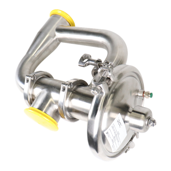
The cover and the valve body are clamped together. The valve body and the seat are welded together. The CPM-I-D60 consists of upper and lower valve bodies, an inlet tube, a cover, a valve plug with diaphragm unit and clamps. The cover and the valve bodies are clamped together. -
Page 31: Selection / Pressure Drop - Capacity Diagram
6 Technical data It is important to observe the technical data during installation, operation and maintenance. Inform the personnel about the technical data. 6.2 Selection / Pressure drop - capacity diagram NOTE! NOTE! NOTE! For the diagrams the following applies: Medium: Water (20°C) (68°F). -
Page 33: Parts Lists And Service Kit
7 Parts lists and service kit It is important to observe the technical data during installation, operation and maintenance. Inform the personnel about the technical data. 7.1 CPM-I-D60... - Page 34 7 Parts lists and service kit It is important to observe the technical data during installation, operation and maintenance. Inform the personnel about the technical data.
- Page 35 7 Parts lists and service kit It is important to observe the technical data during installation, operation and maintenance. Inform the personnel about the technical data. Parts Parts Parts list list list Pos. Denomination Washer Guide O-ring � Plug Seal ring �...
-
Page 37: Booster
7 Parts lists and service kit It is important to observe the technical data during installation, operation and maintenance. Inform the personnel about the technical data. 7.2 Booster... - Page 38 7 Parts lists and service kit It is important to observe the technical data during installation, operation and maintenance. Inform the personnel about the technical data.
- Page 39 7 Parts lists and service kit It is important to observe the technical data during installation, operation and maintenance. Inform the personnel about the technical data. Parts Parts Parts list list list Pos. Denomination Booster housing Lock nut Washer Spring washer Booster piston Diaphragm Booster cover...
- Page 40 © Alfa Laval Corporate AB This document and its contents is owned by Alfa Laval Corporate AB and protected by laws governing intellectual property and thereto related rights. It is the responsibility of the user of this document to comply with all applicable intellectual property laws. Without limiting any rights related to this document, no part of this document may be copied, reproduced or transmitted in any form or by any means (electronic, mechanical, photocopying, recording, or otherwise), or for any purpose, without the expressed permission of Alfa Laval Corporate AB.
Need help?
Do you have a question about the CPM-I-D60 and is the answer not in the manual?
Questions and answers