Eagle FishEasy 245DS Portable Installation And Operation Instructions Manual
Fish-finding & depth-sounding sonars
Hide thumbs
Also See for FishEasy 245DS Portable:

Related Manuals for Eagle FishEasy 245DS Portable


Summary of Contents for Eagle FishEasy 245DS Portable
- Page 1 Pub. 988-0143-831 www.eaglesonar.com FishEasy 245DS, FishEasy 245DS Portable & SeaFinder 245DS Fish-Finding & Depth-Sounding Sonars Installation and Operation Instructions...
- Page 2 245DS is a registered trademark of LEI ® Eagle Electronics may find it necessary to change or end our policies, regulations, and special offers at any time. We reserve the right to do so without notice. All features and specifications subject to change without notice.
-
Page 3: Table Of Contents
Table of Contents Introduction..................1 Specifications: FishEasy 245DS & SeaFinder 245DS .......1 How Sonar Works.................3 Preparations ..................4 Installation ...................5 Recommended Tools and supplies...........6 Selecting a Transducer Location .............6 How low should you go? ..............8 Shoot-Thru-Hull vs. Transom Mounting ........9 Transom Transducer Assembly and Mounting ......10 Trolling Motor Bracket Installation..........15 Transducer Orientation and Fish Arches........16 Shoot-Thru-Hull Preparation ............18... - Page 4 ® Grayline .....................43 Chart Speed ..................45 Frequency ...................46 Fish I.D. ...................47 FishTrack™ ..................49 Alarms....................49 Fish Alarm ..................49 Depth Alarms ..................50 Shallow Alarm ..................50 Deep Alarm..................51 Battery Alarm..................52 Noise Rejection and ASP ..............53 Depth Display..................54 Temperature Display .................55 Voltage ....................56 Backlight.....................56 Contrast ....................57 Simulator ....................57 Set Language ..................58...
-
Page 5: Introduction
– right out of the box. All you have to do is press the on ( ) key. To get started with your Eagle sonar, first read the installation section. It contains instructions for mounting the sonar unit, the transducer and any optional accessories, such as a speed sensor. - Page 6 Back-up memory:...Built-in memory stores sonar settings when unit is turned off. Sonar Frequency: ......83/200 kHz. Transducers:....A dual search Skimmer transducer with built-in temperature sensor is packed with your unit. It has a wide fish detection area of up to 60º/120º with high sensitivity settings. Operates at boat speeds up to 70 mph (61 kts).
-
Page 7: How Sonar Works
storage in temperatures higher or lower than specified will damage the liquid crystal display in your unit. This type of damage is not covered by the warranty. For more information, contact the fac- tory's Customer Service Department; phone numbers are inside the manual's back cover. -
Page 8: Preparations
A new innovation, the 83 kHz frequency offers superior sonar perform- ance at all depths from very shallow up to 1,000 ft and provides up to 120º of fishfinding coverage. Preparations The following shows the recommended sequence for installing the transducer: CAUTION: You should read over this entire installation section before drill-... -
Page 9: Installation
3. Determine the location of your battery or other power connection, along with the power cable route. 4. Install the transducer and route the transducer cable to the sonar unit. 5. Route the power cable from the unit's location to an appropriate power source and connect it there. -
Page 10: Recommended Tools And Supplies
Recommended Tools and supplies If you prefer the option of routing the cable through the transom, you will need a 5/8" drill bit. Each transom mount requires use of a high quality, marine grade above- or below-waterline caulking compound. NOTE: The following installation types also call for these recommended tools and required supplies (supplies are not included): Single-frequency transom installations... - Page 11 at speeds faster than 35 mph. Typically, a good transom location on aluminum boats is between the ribs closest to the engine. 3. The transducer should be installed with its face pointing straight down, if possible. For shoot-thru applications: Many popular fishing boat hulls have a flat keel pad that offers a good mounting surface.
-
Page 12: How Low Should You Go
CAUTION: Clamp the trans- ducer cable to transom near the transducer. This will help prevent the transducer from entering the boat if it is knocked off at high speed. Good location Poor location Good location Good location Poor angle Good and poor transducer locations. How low should you go? For most situations, you should install your Skimmer transducer so that its centerline is level with the bottom of the boat hull. -
Page 13: Shoot-Thru-Hull Vs. Transom Mounting
to loosen the screws and slide the transducer up or down.) If you fre- quently lose bottom signal lock while running at high speed, the trans- ducer may be coming out of the water as you cross waves or wakes. Move the transducer a little lower to help prevent this. -
Page 14: Transom Transducer Assembly And Mounting
Fourth, a Skimmer transducer with a built-in temp sensor will show only the temperature of the bilge, not the water surface temp. Follow the procedure listed in the shoot-thru-hull installation section at the end of this lesson to determine if you can satisfactorily shoot through the hull. - Page 15 If the transducer's face isn't parallel with the ground, remove the transducer and ratchets from the bracket. Place the ratchets into the holes in the bracket with the letter "B" aligned with the dot stamped in the bracket. Reassemble the transducer and bracket and place them against the transom.
- Page 16 Metal washer Rubber washers Metal washer Bolt Assemble transducer and bracket. 4. Drilling mounting holes. Hold the transducer and bracket assem- bly against the transom. The transducer should be roughly parallel to the ground. The transducer's centerline should be in line with the bot- tom of the hull.
- Page 17 Transom Transom Position transducer mount on transom and mark mounting holes. Side view shown at left and seen from above at right. 5. Attaching transducer to transom. Remove the transducer from the bracket and re-assemble it with the cable passing through the bracket over the bolt as shown in the following figures.
- Page 18 Attach the transducer to the transom. Slide the transducer up or down until it's aligned properly with the bottom of the hull as shown in the preceding and following figures. Tighten the bracket's mounting screws, sealing them with the caulking compound. Adjust the transducer so that it's parallel to the ground and tighten the nut until it touches the outer washer, then add 1/4 turn.
-
Page 19: Trolling Motor Bracket Installation
If you need to drill a hole in the transom to pass the connector through, the required hole size is 5/8". (If you intend to route an additional speed or temp sensor cable through the same hole, you will need a 1" (25.4 mm) drill bit instead.) Caution: If you drill a hole in the transom for the cable, make sure it is... -
Page 20: Transducer Orientation And Fish Arches
Position the transducer to aim straight down when the motor is in the water. Tighten the strap securely. 3. Route the transducer cable alongside the trolling motor shaft. Use plastic ties (not included) to attach the transducer cable to the trolling motor shaft. - Page 21 Partial fish arches Transducer aimed Transducer aimed too far forward too far back Full fish arch Proper transducer angle Transducer angles and their effects on fish arches. If the arch slopes up – but not back down – then the front of the trans- ducer is too high and needs to be lowered.
-
Page 22: Shoot-Thru-Hull Preparation
Shoot-Thru-Hull Preparation Hulls with Flotation Materials The transducer installation inside a fiberglass hull must be in an area that does not have air bubbles in the resin or separated fiberglass lay- ers. The sonar signal must pass through solid fiberglass. A successful transducer installation can be made on hulls with flotation materials (such as plywood, balsa wood or foam) between layers of fiberglass if the material is removed from the chosen area. -
Page 23: Testing Determines Best Location
sonar signal must pass through solid fiberglass. Any air bubbles in the fiberglass or the epoxy will reduce or eliminate the sonar signals. Transducer location (high speed) Transducer location (trolling speed) Shoot-thru-hull transducer locations for high speed or trolling speed operation. Testing Determines Best Location Ideally, the shoot-thru transducer should be installed as close to the transom as possible, close to the centerline. - Page 24 True bottom Second bottom Manual range setting Example of a second bottom signal. Unit is in 30 feet of water, with range set at 80 feet and sensitivity set at 87 percent. 3. Now move the transducer around to find the best location with the strongest possible bottom signal.
-
Page 25: Shoot-Thru-Hull Installation
Shoot-Thru-Hull Installation 1. Make sure the area is clean, dry and free of oil or grease, then sand both the inside surface of the hull and the face of the transducer with 100 grit sandpaper. The sanded hull area should be about 1-1/2 times the diameter of the transducer. -
Page 26: Power Connections (Permanent Mount Only)
2. The epoxy consists of the epoxy itself and a hardener. Remove the two compounds from the package and place them on the paper plate. Thoroughly stir the two compounds together until the mixture has a uniform color and consistency. Do not mix too fast or bubbles will form in the epoxy. - Page 27 CAUTION: When using the unit in a saltwater environment, we strongly rec- ommend that you shut off the power supply to the power cable when the unit is not in use. When the unit is turned off but still connected to a power supply, electrolysis can occur in the power ca- ble plug.
-
Page 28: Mounting The Sonar Unit: In-Dash, Bracket Or Portable
positive lead, black is negative or ground. Make sure to attach the in- line fuse holder to the red lead as close to the power source as possible. For example, if you have to extend the power cable to the battery or power buss, attach one end of the fuse holder directly to the battery or power buss. - Page 29 Holes in the bracket’s base allow wood screw or through-bolt mounting. You may need to place a piece of plywood on the back side of thin pan- els to reinforce the panel and secure the mounting hardware. 82.7 107.5 [3.26] [4.23] [6.26] 12.09 [0.48]...
- Page 30 a good marine caulking compound. (Some marine dealers stock cable hole covers to conceal the opening.) Using the Quick Release Mounting Bracket These units use a quick release mounting bracket. When you run the cables through the bracket's cable slots, make sure you allow enough slack for tilting the unit and attaching the connector.
- Page 31 the front of the bracket as you lower it into position.) As you push down, the unit will lock into place with a distinct click. To adjust the viewing angle, pinch the ratchets with one hand, then tilt the unit with your other hand. Release the ratchets and the unit locks into the new position.
-
Page 32: Portable Sonar Installation
Portable Sonar Installation Like many Eagle products, the FishEasy 245DS and SeaFinder 245DS sonar units are capable of portable operation. They use the optional PPP-12 portable power pack. The power pack and portable transducers expand the uses for your sonar. -
Page 33: Installing The Batteries
Installing the Batteries Open the case and lay it flat. (The latch is located below the handle.) Insert eight "AA" size batteries into the battery adapter and place it in the battery compartment. Slip the battery cover tabs into the slots in the case wall, then close the battery cover with the thumb screw. -
Page 34: Mounting The Unit
Mounting the Unit A quick-release mount is built into the top of the portable power pack. To attach the unit, first plug in the cable connector. Then, hold the sonar unit vertically and slide it onto the bracket from above. (The back of the unit should be touching the front of the bracket as you lower it into position.) As you push down, the unit will lock into place with a distinct click. -
Page 35: Portable Transducer Assembly
fresh ones. Always remove batteries from the compartment when storing the unit because dead batteries can leak and corrode the contacts. In cold weather the efficiency of dry cell batteries drops with the tem- perature. We find it a good idea to have the batteries and the sonar unit good and warm before we leave home. - Page 36 nylon cord here Screw Suction Bolt Washer Washer Transducer Moisten the suction cup, then press it onto the hull as firmly as possi- ble. Tie the nylon cord to the boat and set the power pack and sonar unit in a location for easy viewing.
-
Page 37: Portable Transducer Storage
Portable Transducer Storage There is room inside the power pack for the portable transducer. When you're finished fishing, tilt the sonar down to the storage position. Open the case and lay it flat. Unplug the power connector from the battery compartment socket. Wrap the transducer cable around the suction cup, then stow the transducer on top of the battery compartment cover. - Page 38 Notes...
-
Page 39: Operation
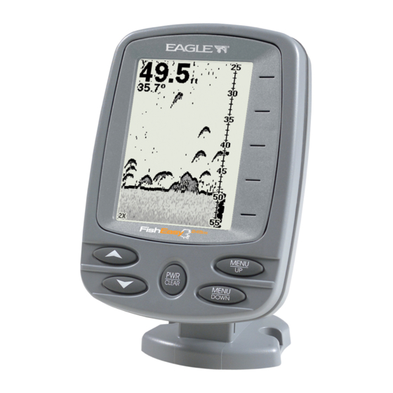
Operation Keyboard Basics The unit sounds a tone when you press any key. This tells you the unit has accepted a command. Numbers in the figure correspond to key ex- planations below: Eagle FishEasy 245 DS. -
Page 40: Memory
1. PWR/CLEAR In this manual, the Power/Clear key is referred to as . Press this key to turn the unit on and off. It also clears menus and menu selec- tions from the screen. To clear a menu from the screen, press NOTE: Hold the key down for five seconds to turn off the unit. -
Page 41: Display
keys access these features, allowing you to customize unit set- MENU tings. To switch menus, press repeatedly. Press to clear menus MENU from the screen. The Backlight menu with backlight turned on. Display The lights will flash for about 10 seconds when the unit is turned on. The backlight menu will appear on the screen. -
Page 42: Full Chart
Digital depth Surface signal Water Temp Fish symbols Bottom signal Structure or cover Depth range at bottom of Grayline depth scale Opening screen, Full Chart page, or mode. The factory default setting has the Fish I.D. (fish symbols) turned on. Full Chart The unit's default page, Full Chart shows all echoes scrolling across the full screen. -
Page 43: Zoom
Digital depth Surface clutter Water Temp Bait fish Structure or cover Bottom signal Fish arches Depth range at bottom of Grayline depth scale Full Chart page, showing digital depth (above) and temp (below). The Fish I.D. feature is turned off. This unit has the following depth ranges: 10, 20, 40, 80, 150, 300, 600, 1000 and 2000 feet. - Page 44 is 0 to 60 feet, Zoom will show an enlarged view of the water column from 30 feet to 60 feet, always keeping the bottom in view. To zoom in the display, repeatedly press until the menu MENU appears. Press to select , then press to clear the menu.
-
Page 45: Sensitivity
ual Depth Range mode, you can select one of 17 pre-set Zoom Ranges. This lets you enlarge a segment of the water column. To do this, make sure Depth Range is set to manual mode. Next, re- menu appears. Press ↓ to select peatedly press until the MENU... - Page 46 Sensitivity set to manual mode (left). Sensitivity scroll bar (right). You can change the sensitivity level whether you are in Auto Sensitivity mode or Manual Sensitivity mode. The adjustment method works the same in both modes, but gives you slightly different results. To adjust sensitivity in Auto Mode: Repeatedly press until the...
-
Page 47: Grayline
Bait school Fig. 1 Fig. 2 Fish arches Fig. 3 Fig. 4 These figures show results of different sensitivity levels on the same location. Fig. 1: Sensitivity at 98 percent, determined by Auto Sensitiv- ity. Typical of full auto mode. Fig. 2: Sensitivity set at 71 percent. Fig. 3: Sensitivity set at 47 percent. - Page 48 Grayline scroll bar. If you have two signals of equal size, one with gray and the other with- out, then the target with gray is the stronger signal. This helps distin- guish weeds from trees on the bottom or fish from structure. Grayline is adjustable.
-
Page 49: Chart Speed
Wider Thin or no Grayline Grayline A small amount of Grayline indicates a soft bottom (left), probably sand or mud. More Grayline indicates a harder, rocky bottom (right). Chart Speed The speed at which echoes scroll across the screen is called the chart speed. -
Page 50: Frequency
Sometimes, you may achieve better images as you decrease the chart speed to match the speed of your boat. If you are at anchor, ice fishing or fishing from a dock, experiment with a chart speed of 25 percent. If you are drifting slowly, try a chart speed of 50 percent. -
Page 51: Fish I.d
fresh and salt water sport fishing applications. When you get into very deep salt water, up to 1,000 feet, the 83 kHz frequency will work best. The 200 kHz transducer will give you better detail and definition, but less depth penetration. You will not get as much detail or definition with the 83 kHz frequency, but it has greater depth penetration and up to 120°... - Page 52 Fish arches Fish I.D. symbols Underwater scene in normal fish arch mode (left). Fish I.D. menu with the feature turned on (right). To see what is under your boat in maximum detail, we recommend you turn off Fish I.D. and begin learning to interpret fish arches. You may see Fish I.D.
-
Page 53: Fishtrack
To turn Fish I.D. off, repeatedly press until the menu ap- MENU pears. Press to select , then press . To turn it back on, repeat ↓ the above steps, but press to select ↑ FishTrack™ The FishTrack feature shows the depth of a fish symbol when it ap- pears on the display. -
Page 54: Depth Alarms
To turn on Fish I.D., repeatedly press until the menu ap- MENU pears. Press to select , then press . Repeatedly press ↓ MENU til the menu appears. Press to select , then press ↑ LARM To turn on Fish I.D., repeatedly press until the menu ap- MENU... -
Page 55: Deep Alarm
Shallow Alarm menu (left). Shallow Alarm Value Dialog box (right). Press . The Shallow Alarm Value dialog box will appear. ↓ ALUE Use ↑ ↓ to enter the first number in the dialog box, then press MENU to move to the next digit. Repeat those steps until the desired DOWN depth has been entered in the dialog box. -
Page 56: Battery Alarm
Deep Alarm menu (left). Deep Alarm dialog box (right). Press the . The Deep Alarm Value dialog box will appear. ↓ ALUE to enter the first number in the dialog box, then press ↓ MENU to move to the next digit. Repeat those steps until the desired DOWN depth has been entered in the dialog box. -
Page 57: Noise Rejection And Asp
Battery Alarm menu (left). Low Battery Alarm Value (right). To move the cursor back to any of the previously entered numbers, to return to the Battery Alarm menu. Use ↑ press . Press MENU UP to select , which will turn on the alarm, then press to clear the menu. -
Page 58: Depth Display
Noise Rejection menu. The ASP feature has three settings — Off, Low and High. When first turned on, noise rejection is set on low. If you have high noise levels, try using the high ASP setting. If, however, you are having trouble with noise, we suggest you take steps to find the interference source and fix it, rather than continually using the unit with the high ASP setting. -
Page 59: Temperature Display
Depth menu with Depth display turned off (left). Depth display set to Large (right). Temperature Display Temperature may be displayed on the screen in a small or medium size or can be turned off completely. Temperature menu (left). Temperature display set to small size (right). -
Page 60: Voltage
To display Temperature: Repeatedly press until the menu appears. Use ↑ ↓ MENU EMPERATURE select the size of the temperature display. Press to clear the menu. Voltage menu with the voltage display turned off (left) and with volt- age set to a small display size (right). Voltage The Voltage menu allows you to display battery voltage on the screen in a small or medium size or can be turned off completely. -
Page 61: Contrast
Backlight turned on (left). Contrast scroll bar (right). Contrast The unit’s display contrast is adjustable to suit different lighting condi- tions. It will help you see the screen from different angles or at various times of the day. To adjust the contrast, repeatedly press until the scroll MENU... -
Page 62: Set Language
Simulator menu (left). Languages menu (right). Set Language This unit supports 11 languages: English, French, German, Spanish, Italian, Danish, Swedish, Russian, Czech, Dutch and Finnish. To select a language: 1. Repeatedly press until the Languages menu appears. MENU 2. Use ↑ ↓ to select the desired language. All menus now appear in the language you selected. - Page 63 Notes...
- Page 64 Notes...
-
Page 65: Troubleshooting
Troubleshooting If your unit is not working, or if you need technical help, please use the following troubleshooting section before contacting the factory cus- tomer service department. It may save you the trouble of returning your unit for repair. For contact information, refer to the last page, just inside the back cover of this manual. - Page 66 Weak bottom echo, digital readings erratic, or no fish signals: 1. Make certain the transducer is pointing straight down. Clean the face of the transducer. Oil, dirt and fuel can cause a film to form on the transducer, reducing its effectiveness. If the transducer is mounted in- side the hull, be sure it is shooting through only one layer of fiberglass and that it is securely bonded to the hull.
- Page 67 Try using resistor spark plugs or routing the sonar unit's power and transducer cables away from other electrical wiring on the boat. No fish arches when the Fish I.D. feature is off: 1. Make certain the transducer is pointing straight down. This is the most common problem if a partial arch is displayed.
- Page 68 If no noise is present, turn the pump off, then turn on the VHF radio and transmit. Keep doing this until all electrical equipment has been turned on, their effect on the sonar display noted, then turned off. If you find noise interference from an electrical instrument, trolling motor, pump, or radio, try to isolate the problem.
- Page 69 EAGLE ELECTRONICS FULL ONE-YEAR WARRANTY "We," "our," or "us" refers to EAGLE ELECTRONICS, a division of LEI, the manufacturer of this product. "You" or "your" refers to the first person who purchases this product as a consumer item for personal, family, or household use.
-
Page 70: How To Obtain Service
800-324-1354 8 a.m. to 5 p.m. Central Standard Time, M-F Eagle Electronics may find it necessary to change or end our shipping policies, regulations, and special offers at any time. We reserve the right to do so without notice. -
Page 71: Accessory Ordering Information
1) Your local marine dealer or consumer electronics store. Most quality dealers that handle marine electronic equipment or other consumer electronics should be able to assist you with these items. To locate an Eagle dealer near you, visit our web site, and look for the Dealer Locator (www.eaglesonar.com/Products/HowToBuy/dealers.asp). - Page 72 Visit our web site: www.eaglesonar.com Eagle Pub. 988-0143-831 Copyright © 2006 All Rights Reserved Printed in USA 032306 LEI-Eagle...
Need help?
Do you have a question about the FishEasy 245DS Portable and is the answer not in the manual?
Questions and answers