Advertisement
1.INTRODUCTION
This manual provides instructions and procedures necessary to install, operate
and troubleshoot the Moog Inc. Series 78 Electrohydraulic Industrial Servovalve.
Troubleshooting instructions are outlined to permit the identification of the specific
component(s) suspected of failure.
2. OPERATION
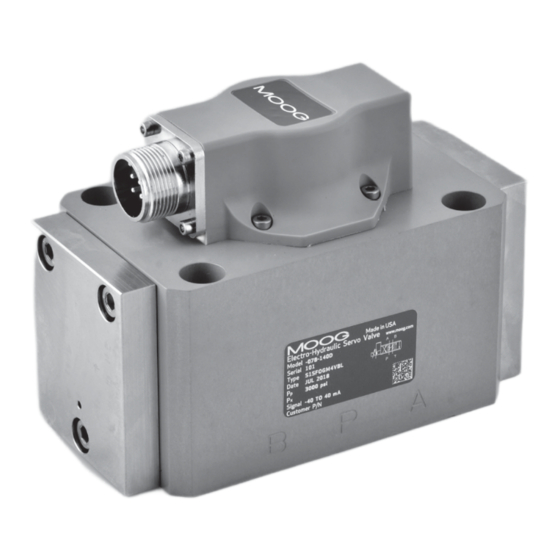
The Moog Inc. Series 78 Electrohydraulic Servovalve consists of a polarized
electrical torque motor and two stages of hydraulic power amplification. The motor
armature extends into the air gaps of the magnetic flux circuit and is supported in
this position by a flexure tube member. The flexure tube acts as a seal between the
electromagnetic and hydraulic sections of the valve. The two motor coils surround the
armature, one on each side of the flexure tube.
The flapper of the first stage hydraulic amplifier is rigidly attached to the midpoint
of the armature. The flapper extends through the flexure tube and passes between
two nozzles, creating two variable orifices between the nozzle tips and the flapper. The
pressure controlled by the flapper and nozzle variable orifice is fed to the end areas of the
second stage spool.
The second stage is a conventional four-way spool design in which output flow from
the valve, at a fixed valve pressure drop, is proportional to spool displacement from the
null position. A cantilever feedback spring is fixed to the flapper and engages a slot at the
center of the spool. Displacement of the spool deflects the feedback spring which creates
a force on the armature/flapper assembly.
Input signal induces a magnetic charge in the armature and causes a deflection of the
armature and flapper. This assembly pivots about the flexure tube and increases the size of
one nozzle orifice and decreases the size of the other.
This action creates a differential pressure from one end of the spool to the other and
results in spool displacement. The spool displacement transmits a force in the feedback
wire which opposes the original input signal torque. Spool movement continues until the
feedback wire force equals the input signal force.
DISASSEMBLY, MAINTENANCE, OR REPAIR OTHER THAN IN ACCORDANCE WITH THE
INSTRUCTIONS HEREIN OR OTHER SPECIFIC WRITTEN DIRECTIONS FROM MOOG, WILL
INVALIDATE MOOG'S OBLIGATIONS UNDER ITS WARRANTY.
CAUTION
78 Series Installation and
Operation Instruction
Electrohydraulic Servovalve
ELECTROHYDRAULIC VALVE CUT-AWAY
Magnet
Coil
Armature
Nozzle
Spool
Filter
Control Port B
Figure 1
Upper Polepiece
Flexure Tube
Flapper
Lower Polepiece
Feedback Wire
Inlet Orifice
Control Port A
Return
Pressure
Advertisement
Table of Contents

Related Manuals for Moog 78 Series


Summary of Contents for Moog 78 Series
- Page 1 2. OPERATION The Moog Inc. Series 78 Electrohydraulic Servovalve consists of a polarized electrical torque motor and two stages of hydraulic power amplification. The motor armature extends into the air gaps of the magnetic flux circuit and is supported in this position by a flexure tube member.
-
Page 2: Hydraulic System Preparation
The hydraulic null position affects the flow output when there is no signal applied. The standard “mechanical null adjust pin” on the Moog 78 series servovalve allows at least +/-20% adjustment. The “mechanical null adjuster” is an eccentric bushing retainer pin located above the port ‘T’... -
Page 3: Troubleshooting Chart
Particulate contamination can cause all of the above, including shifting null bias and degraded performance. A valve that is suspected of contamination should be serviced by Moog to be cleaned and re-calibrated. Table 1.Replacement Parts Figure 3... -
Page 4: Storage Conditions
11. ROUTINE MAINTENANCE GUIDELINES Storage Conditions Every six months or 4,000 operating hours, check for proper operation of the control valve assembly by performing the preventative maintenance steps outlined below. These checks do not require removal of the valve from the We recommend the following ambient conditions for storage: process line. - Page 5 .002 BOSS (1.00 TUBE OD REF) 4 PLACES 4 PL 1.96 Figure 4 Moog Inc., East Aurora, NY 14052-0018 Telephone: 716/652-2000 Fax: 716/687-7910 Toll Free: 1-800-272-MOOG www.moog.com/industrial TJW, Rev. G, July 2024, CDS6569 The products described herein are subject to change at any time without notice, including, but not limited to, product features, specifications, and designs.
Need help?
Do you have a question about the 78 Series and is the answer not in the manual?
Questions and answers