Advertisement
Quick Links
1. INTRODUCTION
This manual provides the instructions and procedures necessary to install,
operate, and troubleshoot the Moog 78N and 760N series servo valves. The
78N and 760N series servo valves are electro hydraulic equipment for hazardous
locations requiring explosion proof protection. The approved hazardous location
markings include:
II 2 G Ex d IIA T3 Gb KEMA 02ATEX2322 X,
0344 per ATEX directive 2014/34/EU
Ex d IIA T3 Gb IECEx DEK 13.0029X
per IECEx certification scheme.
The 78N and 760N series servo valves are also approved by CSA and TIIS
for hazardous locations. They are intended for directional, position, velocity,
pressure, or force control in hydraulic control systems that operate with mineral
based fluids, or others upon request.
2. OPERATION
The Moog 78N and 760N Series Industrial Servo valves consist of a polarized
electrical torque motor and two stages of hydraulic power amplification. The
motor armature extends into the air gaps of the magnetic flux circuit and is
supported in this position by a flexure tube member. The flexure tube acts as a
seal between the electromagnetic and hydraulic sections of the valve. The two
motor coils surround the armature one on each side of the flexure tube.
The flapper of the first stage hydraulic amplifier is rigidly attached to the
midpoint of the armature. The flapper extends through the flexure tube and
passes between two nozzles, creating two variable orifices between the nozzle
tips and the flapper. The pressure controlled by the flapper and nozzle variable
orifice is fed to the end areas of the second stage spool.
The second stage is a conventional 4-way spool design in which output
flow from the valve, at a fixed valve pressure drop, is proportional to spool
displacement from the null position. A cantilever feedback spring is fixed to
the flapper and engages a slot at the center of the spool. Displacement of the
spool deflects the feedback spring which creates a force on the armature/flapper
assembly.
Input signal induces a magnetic charge in the armature and causes a
deflection of the armature and flapper. This assembly pivots about the flexure
tube and increases the size of one nozzle orifice and decreases the size of the
other.
This action creates a differential pressure from one end of the spool to
the other and results in spool displacement. The spool displacement transmits a
force in the feedback wire which opposes the original input signal torque. Spool
movement continues until the feedback wire force equals the input signal force.
CAUTION
DISASSEMBLY, MAINTENANCE, OR REPAIR OTHER THAN IN ACCORDANCE WITH THE
INSTRUCTIONS HEREIN OR OTHER SPECIFIC WRITTEN DIRECTIONS FROM MOOG WILL
INVALIDATE MOOG'S OBLIGATIONS UNDER ITS WARRANTY AND YIELD THE EXPLOSION
PROOF PROTECTION PERMIT NULL AND VOID.
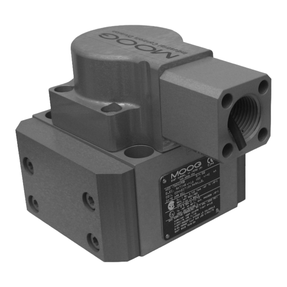
78N/760N Series Installation
and Operation Instruction
Electrohydraulic Servo Valve
(760N shown)
ELECTROHYDRAULIC VALVE CUT-AWAY
Magnet
Coil
Armature
Nozzle
Spool
Filter
Control Port B
Tank
Figure 1 Moog Series 760N
Explosion Proof
Upper Polepiece
Flexure Tube
Flapper
Lower Polepiece
Feedback Wire
Inlet Orifice
Control Port A
Pressure
Advertisement

Subscribe to Our Youtube Channel
Related Manuals for Moog 78N Series


Summary of Contents for Moog 78N Series
- Page 1 2. OPERATION The Moog 78N and 760N Series Industrial Servo valves consist of a polarized electrical torque motor and two stages of hydraulic power amplification. The motor armature extends into the air gaps of the magnetic flux circuit and is supported in this position by a flexure tube member.
- Page 2 EN 60079-0: 2012 and EN 60079-1: 2007 for ATEX and IEC 60079-0: The “mechanical null adjustor” is an eccentric bushing retainer pin 2011 and IEC 60079-1: 2007 for IECEx. Contact Moog for information on the located above the “tank” port designation on the valve body (see Figure 2) dimensions of the flameproof joints.
- Page 3 ID of the filter. Moog for repair. Moog does not authorize any facilities other than Moog or Install the new filter on an inlet orifice and insert it into the filter bore.
- Page 4 Fax: +1-716-687-7910 Toll Free: +1-800-272-MOOG www.moog.com/industrial The products described herein are subject to change at any time without notice, including, but not limited to, product features, specifications, and designs. ©2018 Moog Inc. All changes are reserved. CDS6857 500-489 RevG 0818 Moog • 78N/760N Series Operation Instruction • RevG 08/18...
Need help?
Do you have a question about the 78N Series and is the answer not in the manual?
Questions and answers