Advertisement
Quick Links
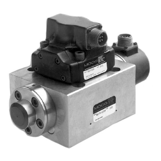
1. INTRODUCTION
This manual provides instructions and procedures necessary
to install, operate and troubleshoot the Moog Inc. Series 79-100 Industrial
Servovalve. Loop closure of the third stage spool requires external electronics –
consult factory for suggested Moog electronics model numbers.
2. OPERATION
The Moog Inc. Series 79-100 Industrial Servovalve consists of a two stage
mechanical feedback pilot valve and a high flow third stage with electrical
feedback. Proper operation requires the use of user provided electronics to
condition the spool position transducer, compare actual spool position to
command and to generate a current signal to the pilot valve.
In a typical system, a spool position command signal is compared to the
actual spool position signal in the servoamplifier.The error (difference) is
converted to a current signal and used to drive the pilot valve spool in the
proper direction.The pilot valve spool directs oil flow to one end of the third
stage spool, moving the spool. Spool movement is sensed by the spool position
transducer and spool motion continues until the spool position signal is equal
to the command signal.At this point, the servoamplifier current returns to near
zero, the pilot valve returns to null and the third stage spool is held in position.
CAUTION
DISASSEMBLY, MAINTENANCE, OR REPAIR OTHER THAN IN ACCORDANCE WITH THE
INSTRUCTIONS HEREIN OR OTHER SPECIFIC WRITTEN DIRECTIONS FROM MOOG WILL
INVALIDATE MOOG'S OBLIGATIONS UNDER ITS WARRANTY.
79-100 Series Installation and
Operation Instruction
Electrohydraulic Servovalve
Advertisement

Related Manuals for Moog 79-100 Series


Summary of Contents for Moog 79-100 Series
- Page 1 Moog electronics model numbers. 2. OPERATION The Moog Inc. Series 79-100 Industrial Servovalve consists of a two stage mechanical feedback pilot valve and a high flow third stage with electrical feedback. Proper operation requires the use of user provided electronics to condition the spool position transducer, compare actual spool position to command and to generate a current signal to the pilot valve.
- Page 2 Part Description Qty. Part Number 4. INSTALLATION Base O-Rings 42082-40 The Moog 79-100 Series Industrial Servovalve may be mounted in any Pilot Valve Base O-Rings 42082-22 position, provided the servovalve pressure, control and return ports match Base X-Y O-Rings 42082-12 respective manifold ports.
- Page 3 Moog Apply required system pressure to servovalve and visually examine for evi- for repair. Moog does not authorize any facilities other than Moog or Moog dence of external leakage. If leakage is present and cannot be rectified by subsidiaries to repair its servovalves.
- Page 4 EXTERNAL PILOT SUPPLY AND RETURN PORTS SHOWN FOR REFERENCE ONLY. MANIFOLD P/N 22236AM3 IS NOT PROVIDED WITH THESE PORTS. Industrial Controls Division Figure 2 Moog Inc., East Aurora, NY 14052-0018 Telephone: 716/655-3000 Fax: 716/655-1803 Toll Free: 1-800-272-MOOG The products described herein are subject to change at any time without notice, including, but not limited to, product features, specifications, and designs.
Need help?
Do you have a question about the 79-100 Series and is the answer not in the manual?
Questions and answers