Table of Contents
Advertisement
Quick Links
1. INTRODUCTION
This manual provides instructions and procedures necessary to install,
operate and troubleshoot the Moog -760K, D760K and E760K Series Industrial
Servovalves. The .760K series valves are electrical equipment for hazardous
areas requiring intrinsic safety or non-incendive protection. The approved
hazardous location markings include:
1G Ex ia IIC/IIB T4 Ga KEMA 02ATEX1015 X
II 3G Ex ec II T3 Gc KEMA 02ATEX1016 X
0344 per ATEX directive 2014/34/EU
Ex ia IIB/IIC T4 Ga IECEx KEM 10.0041X
Ex ec IIC T4 Gc IECEx KEM 10.0041X
per IECEx certification scheme.
The 760K servovalves are also approved by FM, CSA, and TIIS for hazardous
locations. They are intended for directional, position, velocity, pressure and
force control in hydraulic control systems that operate with mineral oil based
fluids. Others on request.
2. OPERATION
The Moog .760K Series Industrial Servovalve consists of a polarized
electrical torque motor and two stages of hydraulic power amplification. The
motor armature extends into the air gaps of the magnetic flux circuit and is
supported in this position by a flexure tube member. The flexure tube acts as a
seal between the electromagnetic and hydraulic sections of the valve. The two
motor coils surround the armature, one on each side of the flexure tube.
The flapper of the first stage hydraulic amplifier is rigidly attached to the
midpoint of the armature. The flapper extends through the flexure tube and
passes between two nozzles, creating two variable orifices between the nozzle
tips and the flapper. The pressure controlled by the flapper and nozzle variable
orifice is fed to the end areas of the second stage spool.
The second stage is a conventional 4-way spool design in which output flow
from the valve, at a fixed valve pressure drop, is proportional to spool displacement
from the null position. A cantilever feedback spring is fixed to the flapper and
engages a slot at the center of the spool. Displacement of the spool deflects the
feedback spring which creates a force on the armature/flapper assembly.
Input signal induces a magnetic charge in the armature and causes a deflection
of the armature and flapper. This assembly pivots about the flexure tube and
increases the size of one nozzle orifice and decreases the size of the other.
This action creates a differential pressure from one end of the spool to
the other and results in spool displacement. The spool displacement causes a
force in the feedback wire which opposes the original input signal torque. Spool
movement continues until the feedback wire force equals the input signal force.
CAUTION
DISASSEMBLY, MAINTENANCE, OR REPAIR OTHER THAN IN ACCORDANCE WITH THE
INSTRUCTIONS HEREIN OR OTHER SPECIFIC WRITTEN DIRECTIONS FROM MOOG WILL
INVALIDATE MOOG'S OBLIGATIONS UNDER ITS WARRANTY AND YIELD THE INTRINSICALLY
SAFE PROTECTION PERMIT NULL AND VOID.
�
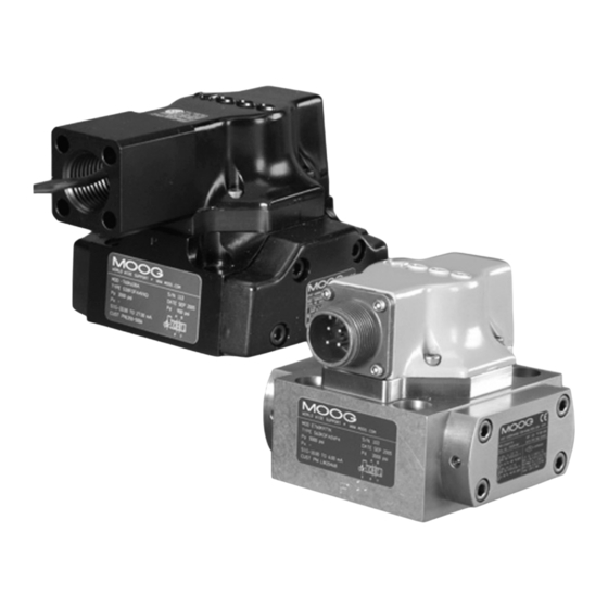
.760K Series Installation and
Operation Instruction
Electrohydraulic Servovalve
Intrinsic Safety Protected
ELECTROHYDRAULIC VALVE CUT-AWAY
Magnet
Coil
Armature
Nozzle
Spool
Filter
Control Port B
Tank
Figure 1 Moog Series .760K
Upper Polepiece
Flexure Tube
Flapper
Lower Polepiece
Feedback Wire
Inlet Orifice
Control Port A
Pressure
Advertisement
Table of Contents

Related Manuals for Moog 760K Series


Summary of Contents for Moog 760K Series
- Page 1 .760K Series Installation and This manual provides instructions and procedures necessary to install, Operation Instruction operate and troubleshoot the Moog -760K, D760K and E760K Series Industrial Servovalves. The .760K series valves are electrical equipment for hazardous Electrohydraulic Servovalve areas requiring intrinsic safety or non-incendive protection. The approved...
- Page 2 The approved safety parameters are listed in the following table for all the system filters are installed during the flushing process whenever the pressure coils used by .760K series. Coil number is marked on the valve nameplate. drop across the filter element becomes excessive. The flushing processes...
- Page 3 12. AUTHORIZED REPAIR FACILITIES Discard O-Rings and filters. Moog does not authorize any facilities other than Moog or Moog subsidiaries Install O-Rings on filter plugs, and O-Rings on inlet orifices. to repair its servovalves. It is recommended you contact Moog at Install filter, inlet orifice assembly, and a filter plug in body.
- Page 4 [25.4] CONTROL PORT B THIS INSTALLATION INSTRUCTION IS CERTIFICATION CONTROLLED. CONTROL PORT A 4 PL REVISION SHALL BE APPROVED BY THE MOOG ICD Ex/ATEX AUTHORIZED PERSON AND MAY REQUIRE APPROVAL BY THE ATEX NOTIFIED BODY. APPLICABLE CERTIFICATE(S): 1.500 KEMA 02ATEX1015 X KEMA 02ATEX1016 X [38.1]...
Need help?
Do you have a question about the 760K Series and is the answer not in the manual?
Questions and answers