Table of Contents
Advertisement
Advertisement
Table of Contents

Subscribe to Our Youtube Channel
Related Manuals for Moog D680 Series


Summary of Contents for Moog D680 Series
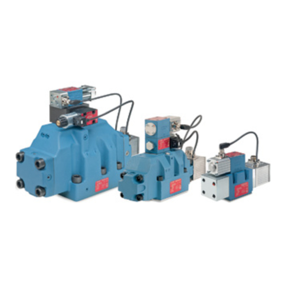
- Page 1 ProPortional Control ValVes Pilot oPerateD WitH inteGrateD eleCtroniCs D680 series iso 4401 siZes 05, 07, 08 anD 10 rev. c, april 2017 2-stage proportional control valves with direct drive pilot stage for demanding applications with high precision and dynamics What moves your World...
-
Page 2: Table Of Contents
www.moog.com/literature/disclaimers. -
Page 3: Product Overview
applications. -
Page 4: Features And Benefits
Features and BeneFits Features and BeneFits Features Benefits d680 series Proportional control valves a 2-stage valve design combining a dynamic pilot stage, cost-effective, high-performance valve that provides... -
Page 5: Description Of Operation
Main stage Version for d683 and d684 (size 08 valves), moog offers two d683/d684 Proportional control valve with standard spool different versions of the main stage: standard spool or stub shaft spool. - Page 6 25 % lower than that of an unbiased d633 pilot valve. hence, the step response times for moog d682 to d684 series proportional control valves with biased pilot valves are slightly slower than with unbiased pilot valves.
- Page 7 (for overlapped spools) or one of the end positions p → a or p → B. moog offers several fail-safe options for the d680 series B V P V A V proportional control valves to suit the needs of different applications.
- Page 8 (Fail-safe) d683/d684 valve with integrated 4/2-way solenoid valve for selecting the Fail-safe Function for applications applications with safety requirements...
-
Page 9: Technical Data
05 - d681 ProPortional valve siZe 05 - d681 ProPortional valve General technical Data technical data and characteristic curves measured with system pressure p of 210 bar (3,000 psi), oil viscosity 32 mm and oil temperature +40 °c (+104 °f). - Page 10 05 - d681 ProPortional valve siZe 05 - d681 ProPortional valve typical static and Dynamic Data 2-stage, with standard spool Valve design d633 unbiased...
- Page 11 05 - d681 ProPortional valve siZe 05 - d681 ProPortional valve Hole Pattern of Mounting surface (3.9) 64.6 the mounting manifold must comform to (0.91)
- Page 12 05 - d681 ProPortional valve siZe 05 - d681 ProPortional valve step response Frequency response With pilot valve d633 unbiased With pilot valve d633 unbiased...
- Page 13 05 - d681 ProPortional valve siZe 05 - d681 ProPortional valve installation drawing for Fail-safe options d, F and m (0.79) (0.39) (0.83) 18.7...
- Page 14 05 - d681 ProPortional valve siZe 05 - d681 ProPortional valve installation drawing for Fail-safe options u and W 55.5 (2.19) (0.79) (0.83) 37.4...
-
Page 15: Size 07 - D682 Proportional Valve
07 - d682 ProPortional valve siZe 07 - d682 ProPortional valve General technical Data technical data and characteristic curves measured with system pressure p of 210 bar (3,000 psi), oil viscosity 32 mm and oil temperature +40 °c (+104 °f). - Page 16 07 - d682 ProPortional valve siZe 07 - d682 ProPortional valve typical static and Dynamic Data 2-stage, with standard spool Valve design d633 unbiased...
- Page 17 07 - d682 ProPortional valve siZe 07 - d682 ProPortional valve Hole Pattern of Mounting surface (4.92) the mounting manifold must conform to (0.47)
- Page 18 07 - d682 ProPortional valve siZe 07 - d682 ProPortional valve step response Frequency response With pilot valve d633 unbiased With pilot valve d633 unbiased...
- Page 19 07 - d682 ProPortional valve siZe 07 - d682 ProPortional valve installation drawing for Fail-safe options d, F and m ø ø (0.43) (0.71)
- Page 20 07 - d682 ProPortional valve siZe 07 - d682 ProPortional valve installation drawing for Fail-safe options u and W 55.5 (2.19) ø ø...
-
Page 21: Size 08 - D683 Proportional Valve
08 - d683 ProPortional valve siZe 08 - d683 ProPortional valve General technical Data technical data and characteristic curves measured with system pressure p of 210 bar (3,000 psi), oil viscosity 32 mm and oil temperature +40 °c (+104 °f). - Page 22 08 - d683 ProPortional valve siZe 08 - d683 ProPortional valve typical static and Dynamic Data 2-stage, with standard 2-stage, with stub shaft...
- Page 23 08 - d683 ProPortional valve siZe 08 - d683 ProPortional valve Hole Pattern of Mounting surface (6.06) the mounting manifold must conform to (0.47)
- Page 24 08 - d683 ProPortional valve siZe 08 - d683 ProPortional valve step response Frequency response With standard spool and pilot valve d633 unbiased...
- Page 25 08 - d683 ProPortional valve siZe 08 - d683 ProPortional valve step response Frequency response With stub shaft spool and pilot valve d633 unbiased...
- Page 26 08 - d683 ProPortional valve siZe 08 - d683 ProPortional valve installation drawing for Fail-safe options d, F and m ø (0.79) 13.5 ø...
- Page 27 08 - d683 ProPortional valve siZe 08 - d683 ProPortional valve installation drawing for Fail-safe options u and W 55.5 (2.19) ø (0.79) 13.5...
-
Page 28: Size 08 - D684 Proportional Valve
08 - d684 ProPortional valve siZe 08 - d684 ProPortional valve General technical Data technical data and characteristic curves measured with system pressure p of 210 bar (3,000 psi), oil viscosity 32 mm and oil temperature +40 °c (+104 °f). - Page 29 08 - d684 ProPortional valve siZe 08 - d684 ProPortional valve typical static and Dynamic Data 2-stage, with standard 2-stage, with stub shaft...
- Page 30 08 - d684 ProPortional valve siZe 08 - d684 ProPortional valve Hole Pattern of Mounting surface (6.06) the mounting manifold must conform to (0.47)
- Page 31 08 - d684 ProPortional valve siZe 08 - d684 ProPortional valve step response Frequency response With standard spool and pilot valve d633 unbiased...
- Page 32 08 - d684 ProPortional valve siZe 08 - d684 ProPortional valve step response Frequency response With stub shaft spool and pilot valve d633 unbiased...
- Page 33 08 - d684 ProPortional valve siZe 08 - d684 ProPortional valve installation drawing for Fail-safe options d, F and m ø (0.79) 13.5 ø...
- Page 34 08 - d684 ProPortional valve siZe 08 - d684 ProPortional valve installation drawing for Fail-safe options u and W 55.5 (2.19) ø (0.79) 13.5...
-
Page 35: Size 10 - D685 Proportional Valve
10 - d685 ProPortional valve siZe 10 - d685 ProPortional valve General technical Data technical data and characteristic curves measured with system pressure p of 210 bar (3,000 psi), oil viscosity 32 mm and oil temperature +40 °c (+104 °f). - Page 36 10 - d685 ProPortional valve siZe 10 - d685 ProPortional valve typical static and Dynamic Data 2-stage, with standard spool Valve design d633...
- Page 37 10 - d685 ProPortional valve siZe 10 - d685 ProPortional valve Hole Pattern of Mounting surface (9.06) the mounting manifold must conform to (0.79)
- Page 38 10 - d685 ProPortional valve siZe 10 - d685 ProPortional valve typical Characteristic Curves flow signal curves at Δp = 5 bar(75 psi) per land, rated flow 1,000 l/min (263.1 gpm)
- Page 39 10 - d685 ProPortional valve siZe 10 - d685 ProPortional valve typical Characteristic Curves flow signal curves at Δp = 5 bar(75 psi) per land, rated flow 1,500 l/min (394.7 gpm)
- Page 40 10 - d685 ProPortional valve siZe 10 - d685 ProPortional valve installation drawing for Fail-safe options d, F and m (15.35) (1.14) 17.2 ø...
- Page 41 10 - d685 ProPortional valve siZe 10 - d685 ProPortional valve installation drawing for Fail-safe options u and W installation drawing (15.35) (1.14) 17.2...
-
Page 42: Electronics
Pin assignment for valves with 6-pole + Pe connector, Pin contacts according to en 175201-804, mating connector (type r or s, metal) with preleading protective earth pin ( ) - Page 43 6-pole + Pe connector ordering code Command signal ±100% spool position actual value ±100 % spool position...
- Page 44 Pin assignment for valves with 11-pole + Pe connector, Pin contacts according to en 175201-804, mating connector (type e, metal) with preleading protective earth pin ( )
- Page 45 11-pole + Pe connector ordering code Command signal ±100% spool position actual value ±100 % spool position...
-
Page 46: Background
Background Background moog d680 series proportional control valves moog d680 series proportional control valves Pilot Pressure and FloW calculation Pilot Pressure and FloW calculation Pilot Pressure to achieve reliable functioning of the valves we Q = Q recommend the following pilot pressure p: •... -
Page 47: Electronics Logic Functions
Enable the moog technical note tn 435: “description of logic HIGH functions”. enable input Time... -
Page 48: Moog Proportional Control Valves For Applications With Safety Requirements
Proportional control valves for applications with safety requirements • the user has to comply with the basic and well-tried installation in safety-related parts of... -
Page 49: Optional Valve Features Upon Request
Features uPon request oPtional valve Features uPon request moog offers a variety of optional features for the d680 series proportional control valves including: • ruggedized valve for operation in demanding environments •... -
Page 50: About Moog
Products at the heart of every moog solution is an array of products engineered for precision, high performance and reliability. for more than six decades, moog products have been specified for critical machine applications. - Page 51 Hydraulic solutions since Bill moog invented the first commercially viable servo valve in 1951, moog has set the standard for world- class hydraulic technology. today, moog products are used in a variety of applications - providing high power, enhanced productivity and ever better performance for some of the worlds most demanding applications.
-
Page 52: Moog Global Support
Background moog d680 series proportional control valves moog d680 series proportional control valves moog gloBal suPPort moog gloBal suPPort moog global support is our promise to help you: • maximize uptime • get more from your machine investment it reflects our commitment to keeping your motion control components and systems running at peak performance. -
Page 53: Ordering Information
Parts accessories and sPare Parts series-specific accessories and spare Parts spare Parts size 05 - D681 Proportional Control Valve Part name... -
Page 54: Accessories And Spare Parts D682 Series
Parts accessories and sPare Parts series-specific accessories and spare Parts spare Parts size 07 - D682 Proportional Control Valve Part name... -
Page 55: Accessories And Spare Parts D683 Series
Parts accessories and sPare Parts series-specific accessories and spare Parts spare Parts size 08 - D683 Proportional Control Valve Part name... -
Page 56: Accessories And Spare Parts D684 Series
Parts accessories and sPare Parts series-specific accessories and spare Parts spare Parts size 08 - D684 Proportional Control Valve Part name... -
Page 57: Accessories And Spare Parts D685 Series
Parts accessories and sPare Parts series-specific accessories and spare Parts spare Parts size 10 - D685 Proportional Control Valve Part name... -
Page 58: Accessories And Spare Parts All Series
Parts accessories and sPare Parts series-independent accessories accessories D680 - Proportional Control Valves Part name Description remark Part number mains power... - Page 59 Parts accessories and sPare Parts Documents D680 - Proportional Control Valves Part name Description remark Part number technical note protective grounding and electrical shielding visit www.moog.com to...
- Page 60 Parts accessories and sPare Parts Mating Connector, straight 6-pole + Pe Ø 22 (0.86) in accordance with en 175201-804, type r, metal, ip65, crimp contact Ø...
- Page 61 Parts accessories and sPare Parts Mating Connector, straight 11-pole + Pe Ø 24 (0.94) in accordance with en 175201-804, type r, metal, ip65, crimp contact Ø...
-
Page 62: Ordering Code
Model number (assigned at the factory) Type designation … D681 to D685 Specification status Series specification – Z Special specification Model designation Factory identification... - Page 63 10 11 12 13 … – Enable function If the enable signal is low: – X – The spool moves to a closed loop controlled neutral position (the HOLD position).
- Page 64 More ProDUCts. More sUPPort. moog designs a range of motion control products to complement those featured in this document. moog also provides service and support for all of our products. for more information, contact the moog facility closest to you.
Need help?
Do you have a question about the D680 Series and is the answer not in the manual?
Questions and answers