Advertisement
Quick Links
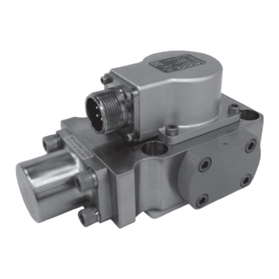
1. INTRODUCTION
This manual provides instructions and procedures necessary to install,
operate and troubleshoot the Moog Inc. Series 730 Electrohydraulic Industrial
Servovalve. Troubleshooting instructions are outlined to permit the identification
of the specific component(s) suspected of failure.
2. OPERATION
The Moog Inc. Series 730 Electrohydraulic Servovalve consists of a
polarized electrical torque motor and two stages of hydraulic power amplification.
The motor armature extends into the air gaps of the magnetic flux circuit and
is supported in this position by a flexure tube member. The flexure tube acts as
a seal between the electromagnetic and hydraulic sections of the valve. The two
motor coils surround the armature, one on each side of the flexure tube.
The flapper of the first stage hydraulic amplifier is rigidly attached to the
midpoint of the armature. The flapper extends through the flexure tube and
passes between two nozzles, creating two variable orifices between the nozzle
tips and the flapper. The pressure controlled by the flapper and nozzle variable
orifice is fed to the end areas of the second stage spool.
The second stage is a conventional four-way spool design in which output
flow from the valve, at a fixed valve pressure drop, is proportional to spool
displacement from the null position. A cantilever feedback spring is fixed to the
flapper and engages a slot at the center of the spool. Displacement of the spool
deflects the feedback spring which creates a force on the armature/flapper
assembly.
Input signal induces a magnetic charge in the armature and causes a
deflection of the armature and flapper. This assembly pivots about the flexure tube
and increases the size of one nozzle orifice and decreases the size of the other.
This action creates a differential pressure from one end of the spool to
the other and results in spool displacement. The spool displacement causes a
force in the feedback wire which opposes the original input signal torque. Spool
movement continues until the feedback wire force equals the input signal force.
DISASSEMBLY, MAINTENANCE, OR REPAIR OTHER THAN IN ACCORDANCE WITH THE
INSTRUCTIONS HEREIN OR OTHER SPECIFIC WRITTEN DIRECTIONS FROM MOOG
WILL INVALIDATE MOOG'S OBLIGATIONS UNDER ITS WARRANTY.
CAUTION
730 Series Installation and
Operation Instruction
Electrohydraulic Servovalve
ELECTROHYDRAULIC VALVE CUT-AWAY
Internal Filter
Inlet Orifice
Magnet
Coil
Armature
Flapper
Spool
Auxiliary First
Stage Pressure
Control Port
Return
Figure 1
Field Replaceable Filter
Upper Polepiece
Flexure Tube
Lower Polepiece
Nozzle
Feedback Wire
Pressure
Control Port
Advertisement

Related Manuals for Moog 730 Series


Summary of Contents for Moog 730 Series
- Page 1 1. INTRODUCTION Electrohydraulic Servovalve This manual provides instructions and procedures necessary to install, operate and troubleshoot the Moog Inc. Series 730 Electrohydraulic Industrial Servovalve. Troubleshooting instructions are outlined to permit the identification of the specific component(s) suspected of failure. 2. OPERATION The Moog Inc.
- Page 2 It is often desirable to adjust the flow null of a servovalve independent of other system parameters. The “mechanical null adjustment” on the Moog 730 Series servovalve allows at least ±20% adjustment of flow null. The Disconnect electrical lead to servovalve.
- Page 3 Moog for repair. Moog does not authorize any facilities other than Moog or Visually inspect filter orifice assemblies for damage or foreign material. Moog subsidiaries to repair its servovalves. It is recommended you contact Discard O-Rings and filters.
- Page 4 4 X PORT PER SAE J1926 Figure 4 1.0625-12 UN-2B DASH 12 STR THD O-RING PRESS BOSS (.75 TUBE OD REF) Moog Inc., East Aurora, NY 14052-0018 PORT PER SAE J1926 2.11 1.23 .4375-20 UNF-2B Telephone:+1-716-652-2000 DASH 4 STR THD O-RING Fax:+1-716-687-7910 4.22...
Need help?
Do you have a question about the 730 Series and is the answer not in the manual?
Questions and answers