Table of Contents
Advertisement
Advertisement
Table of Contents

Related Manuals for TRENDnet TPL-402E


Summary of Contents for TRENDnet TPL-402E
-
Page 2: Table Of Contents
Table of Contents Chapter 1: Product Overview ................3 1.1 Powerline Network Solution ..............3 1.2 Package Contents ..................4 1.3 System Requirements ................4 1.4 Device Label .................... 5 1.5 LEDs ......................5 1.6 Ethernet Port/Buttons ................7 Chapter 2: Product Installation ................ 8 2.1 Initial Installation .................. -
Page 3: Chapter 1: Product Overview
AV Adapter with Bonus Outlet. You can stream HD movies and music, play online multi- player games and much more. Note: This TPL-402E 500Mbps Powerline AV Adapter with Bonus Outlet needs to pair with at least one other IEEE 1901 or HomePlug® AV compatible powerline device. (e.g. TRENDnet Powerline AV products TPL-305E, TPL-303E, TPL-304E, TPL-310AP, TPL-401E, or another TPL-402E). -
Page 4: Package Contents
1.3 System Requirements CD-ROM drive A Desktop or Laptop PC with Network Adapter Installed Existing 10/100/1000Mbps wired network when TPL-402E is used as a bridge de- vice Additional HomePlug® AV or IEEE 1901 compliant powerline adapter Note: Requirement for TPL-402E only, (e.g. -
Page 5: Device Label
1.4 Device Label The device label can be located on the back of the device where the power prong is found. Product Model Device Serial Number Device MAC Address Device Password (DPW) Product Hardware Version Product Firmware Version 1.5 LEDs The LED panel located on the front of the device consists of the status LEDs: Power (PWR), Powerline (PL), and Ethernet Link/Act (ETH). - Page 6 Color Sequence Definition Green Solid Device powered On PWR (Power) Device powered Off Solid Powerline Connected (Connection Quality is Best) (Powerline) Green Syncing or Powerline Data Transmitting/Receiving (Connection Blinking Quality is Best) Note: LED Solid Powerline Connected (Connection Quality is Better) color indicates Amber Powerline Data Transmitting/Receiving (Connection Quality is...
-
Page 7: Ethernet Port/Buttons
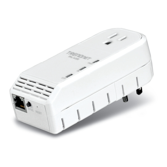
1.6 Ethernet Port/Buttons There is one RJ-45 10/100/1000Mbps Auto-MDIX Gigabit Ethernet port, Reset Button, and Sync Button located at the bottom of the device. Ethernet Port Sync Button Reset Button Button Action Function Initiate Sync/Connection and generate random network name/key on first adapter (PWR LED will start blinking) Match network name/key on secondary or additional adapter and Push/Hold for 2... -
Page 8: Chapter 2: Product Installation
To create a simple powerline network using a pair TPL-402E powerline adapters, simply plug one of your TPL-402E adapters into a wall power outlet in one room and plug the other TPL-402E adapter into an available wall power outlet in another room to establish connectivity between the two rooms. -
Page 9: Initial Installation
Assuming your router is already installed and configured for Internet connectivity and the TPL-402E powerline adapters are at factory default settings. 1. Plug one of the TPL-402E powerline adapters into an available wall power outlet in the room where your router is located. -
Page 10: Securing Your Powerline Network
Powerline Configuration Utility in Chapter 4. Note: The default network name/security key assigned to the TPL-402E is “HomePlugAV”. All powerline adapters in the same powerline network must have the same network name/security key in order to establish connectivity. -
Page 11: Changing The Network Name/Security Key Using The Sync Button
1. Push and hold the Sync button on one of the TPL-402E powerline adapters for 10 seconds and release it. All LEDs will turn off and turn back on. This will erase the current network name/security key assigned to the first powerline adapter. -
Page 12: Adding The Powerline Adapter To An Existing Powerline Network
TPL-402E powerline adapter. 2. Push and hold the Sync button on one of the two TPL-402E powerline adapters that are currently connected to each other for 2 seconds and release it. The PWR LED will start blinking. -
Page 13: Chapter 3: Overlapping Powerline Networks
Chapter 3: Overlapping Powerline Networks It is possible to create multiple powerline networks on the same electrical system separated and grouped by different network names/security keys. The powerline networks will work and communicate independently of each other which can provide security between different groups of powerline adapters. -
Page 14: Move Powerline Adapters Between Different Powerline Networks
Assuming all powerline adapters are TPL-402E adapters and for reference in the diagram and this procedure, the adapters will be labeled Adapter A, B, C, D, and E. Adapters A, B, and C are currently connect together to form one powerline network and Adapters D and E form another powerline network. -
Page 15: Chapter 4: Powerline Configuration Utility
TPL-402E adapters are also connected to your network. 3. Make sure all of the TPL-402E powerline adapters are already connected to each other using the procedures in Chapter 2: Product Installation. 4. The utility is only compatible with Windows operating systems. For details, please refer to Section 1.3. - Page 16 4. At the WinPcap installer window, click Next. Note: The Powerline Configuration Utility requires the use of the WinPcap application. If this prompt does not appear, you may already have the WinPcap application installed. If so, please skip over to Step 9. 5.
- Page 17 6. In the License Agreement window, click I Agree. 7. In the Install Options window, click Install. 8. At the Setup Wizard Completion window, click Finish.
- Page 18 9. The TRENDnet Powerline Configuration Utility installation window will appear automatically. At the Setup Wizard window, click Next. 10. In the License Agreement window, check the radio button I Agree, and then click Next.
- Page 19 11. In the Select Installation Folder window, click Next. 12. In the Confirm Installation window, click Next. 13. At the Installation Complete window, click Close.
-
Page 20: Using The Utility
If you have not already done so, please write down the 16-digit Device Password (DPW) and corresponding MAC Address of each TPL-402E powerline adapter as this will be used to input into the utility. This is located on the Device Label, please refer to Section 1.4. - Page 21 3. Type in the Device Password according to the corresponding MAC address. Then click OK. 4. If successful, the Remote Device will have the Device Password listed next to the device under Password. Note: If the incorrect Device Password is entered, you will receive an error message. Click Enter Password and try entering the password again.
- Page 22 Change the Network Name/Security Key for multiple adapters using the utility 1. Click the Privacy tab. 2. Under Private Network Name, enter the desired network name/security key and click Set All Devices. 3. At the Network Name Setting prompt window, click OK. Applies changes to Local Device only.
-
Page 23: Chapter 5: Troubleshooting
Try power cycling the unit by unplugging it from the wall power outlet for 15 seconds and plugging it back in. If the PL LED is red indicating good quality only, try plugging the TPL-402E into another available wall power outlet to check if you can obtain better connection quality. - Page 24 Power Saving: The device will automatically reduce power usage when the connected devices via Ethernet are powered off, unplugged or inactive for more than 3 minutes. Erp (EuP) Operation: Standby Mode Disconnect the Ethernet cables from the device Ethernet ports, and after 3 minutes, the device will enter standby mode.
-
Page 25: Chapter 6: Specifications
Chapter 6: Specifications Hardware Standards IEEE 1901, HomePlug® AV, IEEE 802.3, IEEE 802.3x, IEEE 802.3u, IEEE 802.3ab Interface 1 x 10/100/1000Mbps Auto-MDIX RJ-45 Port (A: Type B plug) 1 x electrical power socket with noise filtering (12A max. load) (EU: Type C –... - Page 26 Temperature Operating: 0° ~ 40°C (32° ~ 104°F) Storage: -20° ~ 70°C (-4° ~ 158°F) Humidity Max. 90% (non-condensing) Certifications CE, FCC * Maximum of 16 adapters (nodes) recommended for streaming video across your network. Additional adapters may decrease performance. ** 500Mbps is the maximum theoretical Powerline data rate.
- Page 27 Authorization (RMA) number will be issued. An RMA number is required in order to initiate warranty service sup- port for all TRENDnet products. Products that are sent to TRENDnet for RMA service must have the RMA number marked on the outside of return packages and sent to TRENDnet prepaid, insured and packaged appropriately for safe shipment.
- Page 28 Governing Law: This Limited Warranty shall be governed by the laws of the state of California. Some TRENDnet products include software code written by third party developers. These codes are subject to the GNU General Public License ("GPL") or GNU Lesser General Public License ("LGPL").
Need help?
Do you have a question about the TPL-402E and is the answer not in the manual?
Questions and answers