
Related Manuals for Polytec LSV-1000


Summary of Contents for Polytec LSV-1000
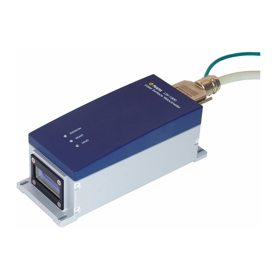
- Page 1 Title Hardware Manual Laser Surface Velocimeter L S V- 1 0 0 0 Terminal Box LSV-A-110...
-
Page 2: Warranty And Service
Include an explanation of the reason for returning it as well as an exact description of the fault. You can find advice on fault diagnosis in CHAPTER Trademarks Brand and product names mentioned in this manual could be trademarks or registered trademarks of their respective companies or organizations. Identification Labels Sensor LSV-1000 Terminal Box LSV-A-110 41312-Man-LSV1000-0809-04en... -
Page 3: Table Of Contents
4.2.1 Installation Concept ....................4-4 4.2.2 Safety Equipment...................... 4-6 4.2.3 Connecting Cable ..................... 4-7 4.2.4 Control and Data Lines ..................... 4-8 4.2.5 Power Supply ......................4-8 5 Initial Start-up 5.1 Functional Test (with Terminal Box)..................5-1 5.2 Configuring the LSV-1000 ....................5-2... - Page 4 9.2.1 General Data ......................9-1 9.2.2 Metrological Properties ....................9-4 9.2.3 Properties of Electrical Interfaces ................9-5 9.2.4 Pin Configuration of the 37-pin Sub-D plug on the Sensor LSV-1000 ......9-7 9.3 Terminal Box LSV-A-110 ......................9-8 9.3.1 General Data ......................9-8 9.3.2 Circuit Diagram ......................9-9 9.3.3 Terminal Diagram.....................
-
Page 5: Safety Information
1 Safety Information 1 Safety Information 1.1 General Safety Information Notes Please read this manual before using the instrument. It will provide you with important information on using the instrument and on safety. This will protect you and prevent damage to the instrument. Pay particular attention to the basic safety information in 1 and the information on installation, CHAPTER... -
Page 6: Information On Laser Safety
Please see 9 for the detailed technical specifications ! CHAPTER Polytec instruments generally comply with the standards IEC and EN • 60825-1 or US 21 CFR 1040.10 and 1040.11 respectively, apart from the deviations in accordance with Laser Notice No. 50 dated July 26, 2001. -
Page 7: Safety Precautions
1 Safety Information In addition to electrical shutdown, the sensor is also equipped with an • electromechanical beam shutter to block the laser beam during both the warm-up phase and work breaks, without having to switch the instrument itself off. This beam shutter is set up to be fail-safe. The user should not attempt to open the housing of the instrument which •... - Page 8 1 Safety Information Protect every instrument not in use against unauthorized use by removing • the key from the key switch ! For laser class 3B instruments, additional safety precautions have to be • complied with in the vicinity of the measurement location. These requirements vary from country to country.
-
Page 9: Laser Warning Labels
1 Safety Information 1.2.3 Laser Warning Labels Warning labels The laser warning labels for the sensor are shown in 1.1. For the FIGURE countries in the European Union (EU), labels 2 to 4 are affixed in the language of the customer's country (see right-hand-side). Laser Radiation Laserstrahlung Avoid exposure to beam... - Page 10 1 Safety Information Position The position of the laser warning labels on the sensor and the beam exit aperture is shown in 1.2. FIGURE int. WARRANTY VOID IF SEAL IS BROKEN OR REMOVED Beam Figure 1.2: Position of the laser warning labels on the sensor and the beam exit aperture...
-
Page 11: Information On Electrical Safety
1.3 Information on Electrical Safety 1.3.1 Safety Information The sensor LSV-1000 is designed to be operated on safety extra low voltage with a nominal value of 24 VDC and can thus not cause a hazard through electric current itself. A condition of safe operation of the sensor is, however, it being supplied with a touch-proof supply voltage which fulfills the isolation requirements of safety extra low voltage (SELV). -
Page 12: Safety Precautions
1 Safety Information 1.3.2 Safety Precautions Pay attention to the following safety precautions when using the instrument: The terminal box LSV-A-110 is only to be connected up using a three-pin • mains cable to AC systems 50 / 60 Hz with a grounded protective conductor which has a nominal voltage of between 100 V and 240 V. -
Page 13: Introduction
Polytec's Laser Surface Velocimeter LSV is an optical measuring instrument for non-contact measurement of one-dimensional surface velocities. The Laser Surface Velocimeter is made up of the LSV-1000 sensor and the LSV-A-110 terminal box. The system components are shown in 2.1. -
Page 14: Area Of Application
2 Introduction 2.2 Area of Application The LSV optically measures the speed of movement of solid surfaces with sufficient optical backscattering properties. Therefore it can be used for non- contact measurement of velocity or length on almost all technical surfaces. To be able to adapt to various operating conditions, sensor heads with stand-off distances of 300 mm, 500 mm, 700 mm and 1 000 mm are available. - Page 15 2 Introduction S e n s o r S e n s o r h e a d h e a d O p t i c a l l y r o u g h O p t i c a l l y s m o o t h s u r f a c e s u r f a c e ( m i r r o r ) Figure 2.2: Schematic diagram of reflection and scattering...
- Page 16 2 Introduction...
-
Page 17: First Steps
3. In the case of a wrong delivery, damage or missing parts, please inform your local Polytec representative immediately and give them the serial number of the sensor. The identification label can be found on the back of the sensor and also on the inside cover of this manual. -
Page 18: Operating And Maintenance Requirements
3 First Steps 3.2 Operating and Maintenance Requirements The LSV should only be stored in an ambient temperature range of 15°C to Ambient conditions 65°C ( 5°F... 149°F), as otherwise irreversible damage can be done to the laser system. The LSV may only be used at an ambient temperature or respectively at a temperature of the mounting surface between ... - Page 19 At a calibration, carried out by Polytec, besides of the determination of the fringe spacing the sensor will be checked, cleaned and preventively maintained.
-
Page 20: Control Elements
3 First Steps 3.3 Control Elements 3.3.1 Sensor LSV-1000 Top view The top view of the sensor is shown in 3.1. FIGURE EMISSION READY VALID 1 2 3 Figure 3.1: View of sensor from above VALID L The L lights up if valid measurement values have been attained. -
Page 21: Identification Label
The front and rear view of the sensor is shown in 3.4. FIGURE view MAC: xx-xx-xx-xx-xx-xx Manufactured by: Manufactured by: GmbH D-76337 W D-76337 Waldbronn, Germany aldbronn, Germany LSV-1000 Model No.: Model No.: Serial No.: Serial No.: x xx xxxx x xx xxxx Mfg.-Date: mm.yyyy Cert No. Cal. Date xx.xx.xxxx... -
Page 22: Terminal Box Lsv-A-110
If the internal fuse goes, then a system fault can be assumed. In this case it is necessary for the instrument to be checked over by Polytec! As a general rule, electrical connections to the device may only ever be made by qualified personnel conversant with the electrical engineering and industrial electronics safety standards. - Page 23 3 First Steps Terminal block XL1 24 V mains supply Power supply T1 with internal fuse Power supply 24 VDC / 2.5 A for sensor and peripherals Ethernet connection module A2 RJ45 jack to connect up to an Ethernet network and connection terminals for connecting the Ethernet cable to the sensor.
- Page 24 3 First Steps Bottom view The bottom of the terminal box LSV-A-110 is shown in 3.4. FIGURE Figure 3.4: Bottom of terminal box LSV-A-110 Cable gland M25 Cable bushing for the connecting cable to the sensor Cable gland M12 and M16 Cable bushing for control and interface cables Cable gland M16 Cable bushing for the Ethernet cable to the sensor...
-
Page 25: Installation
4 Installation 4 Installation 4.1 Assembly 4.1.1 Sensor Position The sensor should be mounted above or to the side of the object where possible to avoid the front window being damaged or soiled by falling particles. The longitudinal axis of the sensor must be at right angles to the surface of the measurement object in both directions and the plane of the laser beams must be in the direction of travel of the object under investigation (measurement direction), refer to... - Page 26 0.1 % is shown for the various sensor models in 4.1. TABLE Table 4.1: Nominal stand-off distance and depth of field for the various sensor models Nominal stand-off distance % depth of field Sensor model LSV-1000-30 ± 20 LSV-1000-50 ± 30 LSV-1000-70 ± 40 LSV-1000-100 1 000 ±...
-
Page 27: Terminal Box
Because of its robust design with protection level IP 67, operation of the terminal box LSV-A-110 is also possible in harsh ambient conditions. The installation concept of the LSV-1000 is designed so that all the electrical connections from all system components and data interfaces are grouped together near the sensor. -
Page 28: Electrical Connections
4 Installation 4.2 Electrical Connections 4.2.1 Installation Concept The LSV-1000 is a compact sensor with integrated control and data interfaces. All electrical connections with the exception of the Ethernet interface are on the 37-pin Sub-D plug of the sensor. The recommended installation concept in accordance with 4.2 is designed to run all... - Page 29 4 Installation For special applications in which the sensor LSV-1000 is a constituent part of a complete measurement system (e.g. C-brackets for rolling mills), it can of course also be operated without the terminal box. The wires from the connecting cable required in this case lead directly to their individual connection points.
-
Page 30: Safety Equipment
Of central importance when installing laser systems is the safety concept to protect people from emitted laser radiation. The sensor LSV-1000 is a laser system in the class 3B within the meaning of the European standard EN 60825-1, which requires certain protective measures to be taken for it to be operated safely (refer also to 1.2). -
Page 31: Connecting Cable
A shielded cable with twisted pairs of wires and a 37-pin Sub-D plug at the sensor end is used as a connecting cable to the sensor. On delivery of the LSV-1000 with the terminal box LSV-A-110, the second cable end is connected to the terminals in the terminal box. As standard, connecting cables 5 m, 10 m or 15 m long are available. -
Page 32: Control And Data Lines
4.2.5 Power Supply Depending on the conditions of use of the LSV-1000, you have different power supply options for the sensor and peripheral components. In any case, please pay attention to the following advice to ensure the electrical safety of the instrument and the whole system. - Page 33 Housing and mounting plate of the terminal box LSV-A-110 are connected to the protective conductor (PE) if the mains connection has been done properly. The housing of the sensor LSV-1000 is also connected to the protective conductor via the brown and red wire at terminal XL6:1. This connection is...
- Page 34 Afterwards, tighten the cable glands to ensure it provides effective strain • relief for the cable. Permanent The mains connection of the LSV-1000 can also be permanently installed if connecting required. The terminals are suitable for solid wires with a profile of up to cable 2.5 mm...
-
Page 35: Initial Start-Up
5 Initial Start-up 5.1 Functional Test (with Terminal Box) Carry out the first functional test of the LSV-1000 with the terminal box LSV-A-110. The functional test can be carried out on a rotating shaft or disc. You can, of course, alternatively use any measurement object which is moved within the measurement volume. -
Page 36: Configuring The Lsv-1000
The service interface can be used completely independently of the wiring of the other two data interfaces and in the state the LSV-1000 is delivered in, works at a transfer rate of 115 200 Baud. - Page 37 As no standardized pin configuration exists for RS-422, this interface is only accessible via terminals 6 to 10 in the terminal block XL5. This interface also works in the state the LSV-1000 is delivered in with a transfer rate of 115 200 Baud.
- Page 38 5 Initial Start-up...
-
Page 39: Function Of The Interfaces
The various control and data lines for linking the LSV-1000 up to your process are grouped together to galvanically isolated groups with separate grounding connections. With the exception of the RS-232 interface only intended for... -
Page 40: Serial Interface Rs-232
Using a special programming cable between the PC and connection module A1, which connects pin 9 to pin 5, the main processor of the LSV-1000 can be transferred into programming mode. In this state for example, a firmware... -
Page 41: Serial Interface Rs-422
6 Function of the Interfaces Configuration The standard configuration of the interface RS-232 is as follows: Transmission rate: 115 200 Baud Data format: 8 data bits, 1 stop bit, no parity bit RS-232(X)cable to PC: 2 x 9-pin Sub-D jack, null modem cable (cross- wired) The pin configuration of the serial service interface is shown in 6.2 and... -
Page 42: Encoder Interface
6 Function of the Interfaces Configuration The standard configuration of the serial interface RS-422 is as follows: Transmission rate: 115 200 Baud Data format: 8 data bits, 1 stop bit, no parity bit The terminal configuration of the RS-422 interface is shown in the following table: Terminal Signal... - Page 43 6 Function of the Interfaces Operating An excerpt from the circuit diagram of the line driver is shown in 6.4. FIGURE modes Optocouplers galvanically isolate the short-circuit proof driver stages for the four signals from the signal processing electronics. The Encoder interface is supplied from an internal, ungrounded power supply with 5 V supply voltage and produces signal levels according to RS-422 standard.
- Page 44 6 Function of the Interfaces Cabling The output signals of the encoder are differential signals. When using differential inputs at the receiver side and suitable cables, a high reliability will be reached with this type of signal. For signals A / and B / respectively, we strongly recommend using twisted pairs which are in a separately installed,...
-
Page 45: Control Signal Inputs
6.5 Control Signal Inputs A total of five inputs with nominally 24 V High level are available to control the LSV-1000 using logical signals from the process. The inputs have got an ungrounded common reference potential (IN_GND) and are isolated from the internal signal processing unit of the sensor by optocouplers. - Page 46 Logical AND or OR operation with TRIG_IN1 DIRECTION Using this input, the LSV-1000 can be fed with directional information from the process. This signal affects the sign of the velocity information at all signal and data outputs of the sensor.
- Page 47 6 Function of the Interfaces Configuration Configuration of the control inputs at terminal block XL3: Terminal Signal Function XL3:1 TRIG_IN1 Input signal for trigger source 1 XL3:2 TRIG_IN2 Input signal for trigger source 2 XL3:3 DIRECTION Velocity sign XL3:4 HOLD Stop for measurement XL3:5 IN_RESERVE...
-
Page 48: Control Signal Outputs
6 Function of the Interfaces 6.6 Control Signal Outputs The LSV-1000 offers a total of 8 digital outputs for linking up control and status devices. The outputs are designed as High-Side switches (PNP type) and switch the externally fed in voltage V1_EXT to the respective active output. - Page 49 (refer to 7.2.3). SECTION If the LSV-1000 is configured for cut mode, then this output provides the advanced warning signal (LENGTH_VOR) which can be used in connection with the cutting signal (LENGTH_CPL) to control a saw (refer 7.2.3).
- Page 50 6 Function of the Interfaces TEMP_OK This output depicts the status of the temperature stabilization for the laser. The signal is only of importance to the status diagnosis of the sensor in extreme ambient temperatures. TEMP_OK = H: The laser temperature is in the target range.
-
Page 51: Parameterization
(refer to 5.2). There are several ways of doing this: SECTION With the aid of the LSV software supplied, control of the LSV-1000 can be • managed on a PC with the operating system Microsoft® Windows®. You will find a detailed description in your software manual. - Page 52 7 Parameterization Take the device Before you can operate the LSV-1000 via an Ethernet network, you have to into operation connect and set up the sensor first. You can also set up several sensors at the same time on the network.
- Page 53 7 Parameterization 9. Click Next and confirm your input by clicking Assign. The software will update the settings on the sensor. This process takes several seconds. 10. Click Finish as soon as it is activated. How to assign IP addresses is also described in the DeviceInstaller manual.
-
Page 54: Selecting Suitable Settings
Adjusting the velocity measurement range to the application conditions, the Range behavior of the LSV-1000 concerning the search time after losing the signal can be optimized. If it takes too long time until the device provides valid measurement values after the material enters the measurement volume, please try to improve this behavior by limiting the measurement range. - Page 55 Set the hold time according to your application as low as possible, but large enough so that areas with invalid measurement values can be bridged. Never set the Hold Time shorter than 0.1 s without consulting Polytec ! Track Delay The track delay is the time for which the sensor must obtain valid data during the search process before giving the status report VALID.
- Page 56 7 Parameterization NOTE ! Set the track delay time according to your application as low as possible, preferably to zero. If the delay time is set too high, then it is possible that the LSV may not be able to complete the search process. Moving Average Every velocity value measured by the sensor first runs through the main filter Filter...
-
Page 57: Special Settings For Length Measurement
Apart from that, the LSV-1000 offers additional setting options which are only effective for length measurement. Apart from interpolation, control of the length measurement through start and stop signals (triggering) is of great importance for attainable measurement accuracy. - Page 58 7 Parameterization 0 Order Interpolation This interpolation procedure is used if you have deactivated the setting Interpolate velocity readings in the software (refer to software manual). The measured course of velocity used for integration with a correctly set hold time is displayed in 7.3.
- Page 59 In the case of length measurement with external triggering, a value X has to be added to the display value, which depends on the arrangement of the trigger sensors at the measurement point. The LSV-1000 automatically carries out this correction if the value X is saved as parameter Offset Length in the sensor.
-
Page 60: Application Examples For Length Measurement With External Trigger Sources
7 Parameterization Cut Mode You configure the LSV-1000 for cutting applications by selecting Cut Mode the trigger source. In this mode signals to cut material to length are emitted at the control signal outputs LENGTH_CPL and MAT_PRES (Cut Mode). You can optionally work with one or two signals. - Page 61 7 Parameterization Light barrier LSV-1000 Laser Surface Velocimeter LB 1 Light barrier LB 2 Laserstrahlung Nicht dem Strahl aussetzen Laser Klasse 3B Nach EN 60825-1 (2008) £ 50 mW/cw; = 650-700 nm Austrittsöffnung für Laserstrahlung Object TRIG_IN1 (LB1) TRIG_IN2 (LB2)
- Page 62 7 Parameterization Length Measurement with Tilted Section You can carry out a length measurement with two light barriers (LS 1, LS 2) with an tilted section of the measurement object. To determine the effective length of the measurement object minus the tilted section, you use a measurement setup as shown in 7.5.
- Page 63 7 Parameterization LSV-1000 Laser Surface Velocimeter Light barrier LB 2 LB 1 Laserstrahlung Nicht dem Strahl aussetzen Laser Klasse 3B Nach EN 60825-1 (2008) £ 50 mW/cw; = 650-700 nm Austrittsöffnung für Laserstrahlung Object TRIG_IN1 (LB1) TRIG_IN2 (LB2) valid Velocity...
- Page 64 7 Parameterization Logical OR Length Measurement with Unknown Location Operation If the side position at which the object comes onto the roller conveyor is unknown, you can trigger the length measurement with the measurement setup shown in 7.6. In doing so, the roller conveyor is scanned with FIGURE two light barriers.
- Page 65 7 Parameterization Light barrier Light barrier LB 1 LB 2 TRIG_IN1 (LB1) TRIG_IN2 (LB2) valid Velocity invalid Measurement active Measured length L Length inactive active Hold Time inactive Length of the object = Measured length L + Distance X Figure 7.7: Measurement setup for length measurement with unknown location Length of the Object To determine the length of the object, the distance X between the light barriers and the laser beam has to be added to the measured length L.
- Page 66 7 Parameterization 7-16...
-
Page 67: Fault Diagnosis
8 Fault Diagnosis 8 Fault Diagnosis In the following you will find a description of some simple tests that you can carry out yourself in the case of malfunction. In the case of more difficult problems with the individual functions, please contact our service personnel. The tests described here are not meant to lead you to carry out maintenance work yourself, but to provide our service personnel with information which is as accurate as possible. -
Page 68: No Velocity Measurement Possible
8 Fault Diagnosis 8.3 No Velocity Measurement Possible If laser light is emitted but making a measurement is not possible, please check the following: Is a moving measurement object with sufficient backscattering properties at the specified stand-off distance in the path of the beam? Is the L VALID on the top of the sensor lit up ? If the L... -
Page 69: Technical Specifications
Danger from radio interference ! - This instrument is in Limit Class A and can cause radio interference in living areas. In this case the user has to implement appropriate precautions. 9.2 Sensor LSV-1000 9.2.1 General Data Laser Laser type:... -
Page 70: Power Supply
9 Technical Specifications Power supply Supply voltage: 18 ... 30 VDC Power consumption: max. 15 W Housing Dimensions: refer to FIGURE Weight: 4.3 kg Protection rating: IP 66 und IP 67 (according to DIN EN 60529) Flatness of mounting surface: 200 µm Torque of mounting screws: max. - Page 71 Beam 150 mm free space for plug and cable EMISSION READY VALID Figure 9.1: Views of the LSV-1000 (Dimensions not specified are given in mm) Beams Figure 9.2: Front view of the LSV-1000 (Dimensions not specified are given in mm)
-
Page 72: Metrological Properties
Sensor velocity velocity of field (typ.) distance field model µm m / min. m / min. LSV-1000-30 ± 20 ± 20 1 330 LSV-1000-50 ± 30 ± 30 1 990 LSV-1000-70 ± 50 ± 40 11.3 2 650... -
Page 73: Properties Of Electrical Interfaces
9 Technical Specifications 9.2.3 Properties of Electrical Interfaces Control Signal Inputs You will find a detailed description of the control signals in 6.5. SECTION = 5 V Max. input voltage LOW: IL max = 11 V Min. input voltage HIGH: IH min = ... - Page 74 9 Technical Specifications Serial Process Interface RS-422 You will find a detailed description of the serial interfaces in 6.3. SECTION Standard: RS-422 (galvanically isolated) Transfer rate: max. 230 400 Baud Data format: 8 data bits, 1 stop bit, no parity bit Cable to the PC: Twisted Pair, shielded (STP) Serial Service Interface RS-232...
-
Page 75: Pin Configuration Of The 37-Pin Sub-D Plug On The Sensor Lsv-1000
9 Technical Specifications 9.2.4 Pin Configuration of the 37-pin Sub-D plug on the Sensor LSV-1000 Pin No. Color Signal Function ye-bl TRIG_IN1 Trigger input 1 ye-rd DIRECTION Measurement direction input ye-bk IN_RESERVE Reserve gy-pk IN_GND Reference potential for inputs wh-bl OUT_GND... -
Page 76: Terminal Box Lsv-A-110
9 Technical Specifications 9.3 Terminal Box LSV-A-110 9.3.1 General Data Mains Connection Input voltage: 100 VAC ... 240 VAC, ± 10 % Frequency range: 45 Hz ... 65 Hz Current consumption: max. 0.4 A at 230 V max. 0.8 A at 115 V Inrush current: <... -
Page 77: Circuit Diagram
9 Technical Specifications 9.3.2 Circuit Diagram Part 1 of 2 gy-pk ye-bk gn-bk ye-rd gn-rd ye-bl gn-bl pk-gn ye-pk ye-gy gy-gn Figure 9.3: Overall circuit diagram terminal box LSV-A-110 (part 1) - Page 78 9 Technical Specifications Part 2 of 2 wh-gn wh-og bn-bk wh-bk gy-bl bn-rd wh-rd bn-bl wh-bl pk-bn wh-pk gy-bn wh-gy ye-bn wh-ye bn-gn wh-gn rd-bl Figure 9.4: Overall circuit diagram terminal box LSV-A-110 (part 2) 9-10...
-
Page 79: Terminal Diagram
9 Technical Specifications 9.3.3 Terminal Diagram Mains connection LAN cable to sensor gy-bl Free bn-rd Internal ENC_GND wh-gn wh-rd SER_GND TXD- wh-og TXD+ RXD- RS-422 RXD+ Encoder out bn-bl +V2_EXT_IN(+5V...+30V) Encoder Out/RS-422 OUT_GND OUT_GND wh-bl OUT_GND pk-bn SERVICE_REQ wh-pk OUT_RESERVE gy-bn TEMP_OK wh-gy... - Page 80 9 Technical Specifications 9-12...
-
Page 81: Appendix A: Theory Of The Measurement Procedure
A Theory of the Measurement Procedure Appendix A: Theory of the Measurement Procedure The LSV operates on the basis of the differential laser Doppler method. The beam of a laser diode is split into two partial beams which are then superimposed again on the surface to be measured. - Page 82 A Theory of the Measurement Procedure The fringe spacing s is a system constant which depends on the laser Fringe spacing wavelength and the angle between the laser beams . ------------------ - Equation A.1 -- - 2 sin When a particle moves through the fringe pattern, the intensity of the light scattered back from it is modulated.
-
Page 83: Appendix B: Command Description For The Interfaces
B Command Description for the Interfaces Appendix B: Command Description for the Interfaces With the data interfaces you have the option to control the LSV-1000 with a PC. In doing so, you can acquire measurement data and carry out a complete parameterization of the device. - Page 84 (Carriage Return), i.e. decimal 13 or hexadecimal 0x0d. Base Unit All information on lengths and velocities refer to the base units set in the sensor LSV-1000. You will find the syntax of the corresponding command in B.2.2. SECTION In the ISO version...
- Page 85 B Command Description for the Interfaces B.2 LSV Settings B.2.1 Parameters for the Serial Interfaces RS-232 and RS-422 OM : [BAUD = N] [,PORT = N] Sets the baud rate of the selected serial interface (refer to B.3, SECTION command Sample). BAUD 9 600 19 200...
-
Page 86: Velocity Measurement
1 / 8 of the values for M = 0. Parameter R reduces the upper measurement range limit by . For R applies: M R (M 6). the factor 2 Not used for LSV-1000... - Page 87 B Command Description for the Interfaces B.2.4 Length Measurement LENgth : [TRIGSRC = N] [,OFFS] [,INT = N] [,LAST = N] [,SYNC = N] [,TRACK] [,HOLD] Sets the settings for length measurements. TRIGSRC Selection of the trigger source 0 = No trigger signal is used 1 = External trigger signal is used 2 = Trigger signal is provided by the function Material Detect 3 = Trigger signal is provided by the function Cut Mode...
- Page 88 B Command Description for the Interfaces LOGIC Sets the logical operation (Trigger Logic) of both trigger signals 0 = Logical OR operation (Trigger 1 OR Trigger 2) 1 = Logical AND operation (Trigger 1 AND Trigger 2) MODE Sets the trigger mode (Input Mode) 0 = Edge 1 = Level POL1...
- Page 89 CORR Correction Factor (Default = 1.000) TCOEF Temperature Coefficient (Default = 11.9961 Can not be set at the LSV-1000. SENS[or] ? [ALL] [,CTRL] [,STAT] [,TEMP] SENS[or] : [CTRL = N] [,STAT = N] Requests or sets the parameters to monitor the sensor.
- Page 90 B Command Description for the Interfaces B.2.6 Configuration of the Encoder Interface ENC[oder] ? [ALL] [,ENA] [,PPL] [,VMAX] ENC[oder] : [ENA] [PPL] [,VMAX] Requests or sets the settings for the optional encoder interface (Encoder Output). 0 = Disables the Encoder Interface 1 = Enables the Encoder Interface Number of pulses per length VMAX...
- Page 91 B Command Description for the Interfaces [Hz] Baud rate 9 600 19 200 38 400 1 024 115 200 VELO Velocity Length SINAD Signal to Interference, Noise and Distortion (SINAD) RATE Data Rate: Number of measurements per second which are internally made by the sensor.
-
Page 92: General Information
BUILD ? [ALL] Reads date and version of the firmware. B.5 General Information Format of Data Sets (Velocity, Length, etc.) Byte 1 shows the status of the sensor LSV-1000. Bit 7, 6, 5 Reserved Bit 4 Valid data available (VALID). - Page 93 B Command Description for the Interfaces IEEE 4-byte Floating Format (IEEE. 754) 1 negative / 0 positive 1 Bit Mantissa sign: 8 Bit Exponent with an offset of 127: 0 2- 127 2 128 2 255 ...
- Page 94 B Command Description for the Interfaces B-12...
-
Page 95: Appendix C: Declaration Of Conformity
C Declaration of Conformity Appendix C: Declaration of Conformity Figure C.1: Declaration of conformity for the LSV -1000... - Page 96 C Declaration of Conformity...
-
Page 97: Index
LSV-1000, specifications electrical connections terminal box LSV-A-110, specifications connection module AND operation, logical 7-10 A1, in the terminal box application... - Page 98 EMC standards encoder interface influences, mechanical configuration initial start-up description functional test, with terminal box sensor LSV-1000, specifications sensor, configuring Ethernet cable, connection terminal box input voltage Ethernet connection module inspection, when unpacking in the terminal box installation concept, electrical connections...
- Page 99 Ethernet interface position, on the sensor operating conditions, adaptation laser, sensor LSV-1000, specifications operating requirements length measurement operating temperature cut mode sensor 7-10 external trigger inputs...
- Page 100 INTERLOCK system summary key switch warning light safety information technical specifications electrical safety sensor LSV-1000 general safety standards applied laser safety terminal box LSV-A-110 safety precautions temperature range electrical safety terminal block laser safety...
- Page 101 Index trigger source, velocity measurement unpacking, components unsuitable handling VALID Led, sensor velocity measurement fault diagnosis hold time moving average filter or length measurement? settings track delay trigger source zero zone warm-up period warning labels instrument warning label, on the terminal laser on the sensor warning light, safety devices warranty, invalidate...
- Page 102 Index...
- Page 103 +81 (0) 45 938-4961 E-mail: info@polytec.de E-mail: info@polytec.co.jp Internet: http://www.polytec.com Internet: http://www.polytec.co.jp USA West Polytec, Inc., North American Headquarters 16400 Bake Parkway, Suites 150 & 200 Irvine, CA 92618 Tel.: +1 949 769 2626 Fax: +1 949 769 2622 E-mail: info@polytec.com Internet: http://www.polytec.com...
Need help?
Do you have a question about the LSV-1000 and is the answer not in the manual?
Questions and answers