
Subscribe to Our Youtube Channel
Related Manuals for Polytec MSA-600


Summary of Contents for Polytec MSA-600
- Page 1 Operating Instructions Title Micro System Analyzer M S A - 6 0 0 Sensor Head MSA-I-620 Front-End MSA-F-620 Controller MSA-E-600 Data Management System MSA-W-620 For MSA-600-X/MSA-600-U Systems...
- Page 2 Warranty and Service The warranty for this equipment complies with the regulations in our general terms and conditions in their respective valid version. This is conditional on the equipment being used as intended and as described in these operating instructions. The warranty does not apply to damage caused by incorrect usage, external mechanical influences, or by not keeping to the operating conditions.
-
Page 3: Table Of Contents
1.6.4 Warning Labels on the Instrument ................1-13 1.7 Information on REACH Regulation ................... 1-13 2 Introduction 2.1 Area of Application ......................2-1 2.2 System Summary ....................... 2-1 2.3 MSA-600 Options ....................... 2-2 2.4 Out-of-Plane-, In-Plane- and Topography Measurements ........... 2-3 2.5 Differential Measurements ....................2-3... - Page 4 Contents 3 First Steps 3.1 Unpacking and Inspection ....................3-1 3.2 Control Elements, Displays, and Connections ..............3-4 3.2.1 Sensor Head ......................3-4 3.2.2 Front-End .........................3-5 3.2.3 Controller ........................3-7 3.2.4 Data Management System ..................3-8 3.3 Assembly ..........................3-12 3.3.1 Sensor Head ......................3-12 3.3.2 Objective Adapter/Objective Turret ................3-13 3.3.3 Objective Positioner (with MSA-A-TMS Option) ............3-14 3.3.4 Holder for Objective Positioner (with MSA-A-TMS Option) ........3-16 3.4 Cabling ..........................3-19...
- Page 5 6.5 MSA-W-620 Data Management System ................6-9 6.5.1 General Data ......................6-9 6.5.2 Industrial PC Configuration ..................6-9 6.5.3 Data Acquisition ....................... 6-9 6.5.4 Function Generator (only MSA-600-X) ..............6-9 6.6 A-ESG-002 Signal Generator ................... 6-10 6.7 Metrological Properties ....................6-10 6.7.1 MSA-600-X/-U ......................6-10 6.7.2 Topography Measurements ..................
- Page 6 Contents...
-
Page 7: Safety Information
1 Safety Information 1 Safety Information Information on Using these Operating Instructions These operating instructions are part of the product. Keep them within • easy reach. Read these operating instructions carefully before operating the • instrument. Pay attention to any documentation provided by other manufacturers. -
Page 8: Mandatory Signs
Any use other than the one described in these operating instructions is not permitted. Polytec rejects any liability for damages which occur from improper use. The instruments are designed in accordance with good engineering practice to meet state-of-the-art safety requirements, have been tested, and left the factory in a condition in which they are safe to operate. -
Page 9: User Qualification
Exchange/installation of Subassemblies may only be exchanged or installed by subassemblies authorized service personnel from Polytec. 1.3.4 Ambient Conditions ATTENTION! Damage to the sensor head caused by impurities! If dust and other dirt particles from the operating environment penetrate the instrument, this can cause lasting damage to the instrument. -
Page 10: Cleaning
Third party hardware or software components could damage the system or impair the function of the software. » To install components which have not been distributed by Polytec, contact Polytec first. » Using Windows Update, do not install any optional updates but only security updates. -
Page 11: Laser Safety
1 Safety Information Laser Safety 1.4.1 Important Warning Notices WARNING! Eye damage caused by incorrect usage of laser radiation! » Position the instrument so that the direct or reflected laser beam is not dangerous. » Do not look directly into the laser beam. »... -
Page 12: Applicable Standards And Directives
Laser Products - Equipment Classification and Requirements). CDRH Compliance Statement Polytec GmbH confirms that its laser products comply with all applicable standards and regulations that are set forth by the United States of America's Health and Human Services (HHS), Food and Drug Administration (FDA), Center for Devices and Radiological Health (CDRH) for laser products. -
Page 13: Warning Labels On The Instrument
1 Safety Information 1.4.5 Warning Labels on the Instrument Laser warning The laser warning labels are shown in the following figure. For countries in the labels European Union (EU), labels [2] to [4] are affixed in the language spoken in the customer's country. - Page 14 1 Safety Information Position of laser The position of the laser warning labels on the sensor head (front and back warning labels view) is shown in the following figure. Figure 1.3: Position of the laser warning labels [1], [2], [3] and [4] as well as the beam exit aperture with the beam direction [5]...
-
Page 15: Lamp Safety
1 Safety Information Lamp Safety 1.5.1 Important Warning Notices WARNING! Damage to eyes caused by high light intensity! » Do not look directly into the illumination module. » Do not use any operating or calibrating equipment other than specified here. 1.5.2 Applicable Standards and Directives The instrument complies with the standards IEC and EN 62471... -
Page 16: Warning Labels On The Instrument
1 Safety Information 1.5.5 Warning Labels on the Instrument Warning labels The lamp warning label is shown in the following figure. For countries in the European Union (EU), the warning label is affixed in the language spoken in the customer's country. Figure 1.4: Lamp warning label Position of lamp... -
Page 17: Electrical Safety
1 Safety Information Electrical Safety 1.6.1 Important Warning Notices WARNING! Fire risk caused by inaccessible or missing disconnection device! A fire risk exists in case of overheating, e.g. due to a device fault. Furthermore, touching hot housing parts can cause burns. The mains switch disconnects the device from the power supply and is used to switch it off in case of danger. -
Page 18: Important Notices
The instrument is subject to EU Directive 2014/30/EU (EMC Directive) and therefore conforms with the limits for emission and immunity specified in the standards it is based on. With the CE marking Polytec confirms that the instrument has been tested successfully. -
Page 19: Warning Labels On The Instrument
1 Safety Information 1.6.4 Warning Labels on the Instrument The warning label is shown in the following figure. Figure 1.6: Warning of residual voltage Information on REACH Regulation Information on the Duty to Register Regulation (EC) No 1907/2006 of the European Parliament and of the Council concerning the Registration, Evaluation, Authorization and Restriction of Chemicals (REACH) regulates the manufacturing, placing on the market and using chemical substances and products derived therefrom. - Page 20 1 Safety Information 1-14...
-
Page 21: Introduction
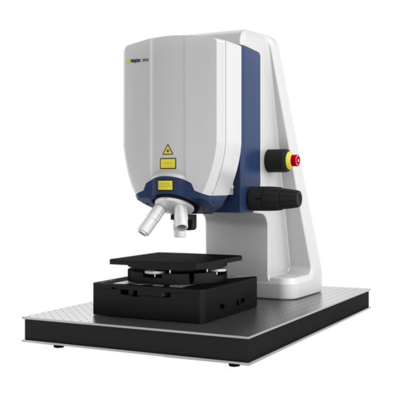
Interference objectives are available for topography measurements and bright field objectives with various magnifications for vibration measurements. Figure 2.1: Summary of system components of the MSA-600 Measurement System, together with accessories available as an option... -
Page 22: Msa-600 Options
The respective software application supports you in configuring the signal generator. MSA-600 Options Options as listed in the following table are available for the MSA-600. Option name Description MSA-600-U This option offers a bandwidth extension of up to 2.5 GHz. -
Page 23: Out-Of-Plane-, In-Plane- And Topography Measurements
2 Introduction Out-of-Plane-, In-Plane- and Topography Measurements With its equipment and by using three software applications, the MSA-600 Measurement System can make a range of different measurements: Out-of-plane measurements: The instrument can acquire measurements • perpendicular to the measurement plane on the basis of laser interferometry and can display and evaluate them with the PSV software. - Page 24 2 Introduction...
-
Page 25: First Steps
3 First Steps First Steps Unpacking and Inspection ATTENTION! Damage to the optics caused by vibration! The optical components are highly sensitive. Shocks or vibrations can cause damage to the components or impair its function. » Protect the unpacked device from being shaken. INFORMATION Components marked with an (*) are described in separate documentations. - Page 26 3 First Steps Components supplied with MSA-W-620 Data Management System: 1 Industrial PC • 1 Wireless keyboard and wireless mouse • 1 TFT monitor with monitor cable and mains cable • 1 USB cable • Additional components supplied with the MSA-A-TMS option: 1 Objective positioner with objective insert and turret insert (incl.
- Page 27 3. In the case of a wrong delivery, damage or missing parts, immediately inform your local Polytec representative, stating the serial number and the manufacturing date of the instruments. 4. Carefully retain the original packaging in case you have to return the...
-
Page 28: Control Elements, Displays, And Connections
3 First Steps Control Elements, Displays, and Connections 3.2.1 Sensor Head Back view The back view of the sensor head is shown in the following figure. Figure 3.1: Back view of the sensor head Warning label Name plate Warning label (residual voltage) SCANNER connection (15-pin Sub-D jack) REF SCANNER connection (15-pin Sub-D jack) SYSTEM main connection (25-pin Sub-D jack) -
Page 29: Front-End
3 First Steps VIDEO network connection RF OUT connection (SMA jack) BC connection (SMA jack) 10 Connection for the protective earth cable to the objective positioner 11 Connection for the protective earth cable to the controller 12 Carriage plate 3.2.2 Front-End Front view The front view of the front-end is shown in the following figure. - Page 30 3 First Steps Back view The back view of the front-end is shown in the following figure. Figure 3.3: Back view of the front-end ACQ/GEN connection (Sub-D jack) REF connection (SMA jack) SIGNAL connection (SMA jack) CONTROL network connection (marked in yellow) SYSTEM main connection (Sub-D jack) Name plate POWER mains connection (socket for standard power cord with built-in fuses)
-
Page 31: Controller
3 First Steps 3.2.3 Controller INFORMATION Depending on which option the MSA-600 is supplied with, the controller equipment and therefore the look of the back can vary. Back view The back view of the controller is shown in the following figure. -
Page 32: Data Management System
3 First Steps 3.2.4 Data Management System Front view The front view of the industrial PC is shown in the following figure. The front flap is shown as transparent. Figure 3.5: Front view of the industrial PC Cooling fan Status display of the industrial PC Status display of the hard disk drive RESET key POWER key... - Page 33 Monitor connections (Mini DisplayPort jacks) Air vents Connection for cable shielding (blade connector) GENERATOR network connection (only MSA-600-U; marked in red) GENERATOR connections of the generator board (only MSA-600-X) 10 CONTROL network connection (marked in yellow) 11 USB connections (Universal Serial Bus, type A)
- Page 34 3 First Steps Data acquisition The connections of the ADQ7DC data acquisition board are shown in the board following figure. Figure 3.7: View of the data acquisition board SYNC signal connection (SMA jack) TRIG signal connection (SMA jack) GPIO signal connection (44-pin High density Sub-D jack) B signal input (SMA jack) X signal input (SMA jack) A signal input (SMA jack)
- Page 35 3 First Steps Generator board The connections of the Spectrum M4i.6630-x8 generator board are shown in the following figure. Figure 3.8: View of the generator board Trg1 signal input (MMCX jack) Clk clock output (MMCX jack) Trg0 trigger input (SMA jack) Clk In clock input (SMA jack) Ch0 signal output (SMA jack) X0 signal connection (MMCX jack)
-
Page 36: Assembly
3 First Steps Assembly ATTENTION! Damage to the optics caused by vibration! The optical components are highly sensitive. Shocks or vibrations can cause damage to the components or impair its function. » Protect the unpacked device from being shaken. ATTENTION! Damage or measurement inaccuracy of the system caused by assembly errors! »... -
Page 37: Objective Adapter/Objective Turret
3 First Steps 3.3.2 Objective Adapter/Objective Turret ATTENTION! Damage to objective positioner by using the wrong objective mount! Due to their design, the A-IOB-005X-B, A-IOB-02X5-B and A-IOB-004X-LD-B Michelson Interference Objectives have a larger parfocal length and mass than the Mirau interference objectives or the bright-field objectives. If you are using the Michelson Interference Objectives together with the objective positioner on the objective turret, the objective positioner can be damaged when you rotate the objective turret. -
Page 38: Objective Positioner (With Msa-A-Tms Option)
3 First Steps 3.3.3 Objective Positioner (with MSA-A-TMS Option) Parts The assembly kit for the objective positioner consists of the turret and description objective insert and the objective positioner itself. For the assembly, you will also need a flat key and the clamping tool enclosed with the assembly kit. The objective insert is already pre-assembled in the objective positioner. - Page 39 3 First Steps Figure 3.11: Place the objective positioner [F] onto the clamping ring [E]. 6. Align the objective positioner so that the cable outlet is pointing backwards. 7. The clamping ring has holes all the way around which can be seen through the recess in the objective positioner.
-
Page 40: Holder For Objective Positioner (With Msa-A-Tms Option)
3 First Steps 3.3.4 Holder for Objective Positioner (with MSA-A-TMS Option) The scope of supply with option MSA-A-TMS includes a holder for the objective positioner. Use this holder when the objective positioner is not in use. Assembly Use the enclosed knurled screws and mount the holder as shown in the following figure. - Page 41 3 First Steps Insert either the objective positioner or the objective adapter into the holder. Refer to the following figures when using the holder. Figure 3.14: Holder with objective positioner 3-17...
- Page 42 3 First Steps Figure 3.15: Holder with objective adapter 3-18...
-
Page 43: Cabling
3 First Steps Cabling WARNING! Electric shock caused by missing protective earth cable! In the case of a fault, missing or improperly connected protective earth cables can lead to dangerous voltages that cause an electric shock when the devices are touched. »... - Page 44 » Check the contact pins before plugging in the cables. » Do not use any force when plugging in the cables. » Replace defective cables with new cables. » If necessary, contact your local Polytec representative. ATTENTION! Damage to the instrument caused by overvoltage! »...
-
Page 45: Connecting The Protective Earth Cable
3 First Steps 3.4.1 Connecting the Protective Earth Cable ATTENTION! Damage to the sensor head caused by improper fastening material! » Only use the provided fastening material to connect up the protective earth cable. The scope of delivery includes all protective earth cables that you need for the safe operation of your measurement system. - Page 46 3 First Steps Controller 1. Connect the protective earth cable to the back of the controller as shown in F 3.16. IGURE 2. Tighten the hexagon nut [D] with a torque of 2.9 Nm. 3. Make sure that the contact resistance is < 0.1 Ω at 25 A at all connection points relevant for mounting the protective earth cables.
- Page 47 3 First Steps Objective 4. Connect the protective earth cable to the objective positioner as shown in positioner (with 3.17. IGURE MSA-A-TMS 5. Tighten the screw [D] with a torque of 1.1 Nm. option) 6. Make sure that the contact resistance is < 0.1 Ω at 25 A at all connection points relevant for mounting the protective earth cables.
- Page 48 3 First Steps Sensor head 7. Feed the protective earth cable of the controller to the left connection for the protective earth cable on the back of the sensor head. 8. Feed the protective earth cable of the objective positioner (with MSA-A-TMS option) to the right connection for the protective earth cable on the back of the sensor head.
-
Page 49: Connecting The Hardware
Mini DisplayPort jack on the back of the industrial PC. 4. Switch on the wireless keyboard and wireless mouse. 5. Plug the hardlock (dongle) for your Polytec software into a free USB connection on the back of the industrial PC. - Page 50 3 First Steps 15. Product variant MSA-600-X with internal generator: Plug the ACQ/GEN into the Sub-D jack on the back of the front-end and Cable (X) ACQ/GEN into the accordingly labeled SMA or MMCX jacks on ACQUISITION ) on the back...
- Page 51 3 First Steps Figure 3.19: Cabling of system components (basic equipment) 3-27...
- Page 52 3 First Steps Figure 3.20: Cabling of system components (options) 3-28...
- Page 53 3 First Steps Figure 3.21: Cabling of the internal generator for the product variant MSA-600-X 3-29...
- Page 54 3 First Steps Figure 3.22: Cabling of the external signal generator A-ESG-002 for the product variant MSA-600-U 3-30...
-
Page 55: Connecting The Signals
4. The function generator signal is available at the BNC jack on the SIGNAL generator (only front of the front-end. MSA-600-X) 5. The synchronization pulse of the generator signal is available at the SYNC BNC jack on the front of the front-end. Function 6. - Page 56 3 First Steps Figure 3.23: Cabling of the directional coupler for the MSA-600-X product variant Figure 3.24: Cabling of the directional coupler and the A-ESG-0002 Signal Generator for the MSA-600-U product variant 3-32...
-
Page 57: Connecting The Mains Cables
The implementation of a first functional test is described in the following. If the instrument does not perform as described, read through the information on troubleshooting in these operating instructions and if required, contact your local Polytec representative. 3.5.1 Out-of-Plane Vibrations To test an out-of-plane vibration with your measurement system, use the UHF-A-SAW SAW Filter. - Page 58 3 First Steps Figure 3.25: Assembly of the SAW filter on the tip-tilt unit Cylinder screw (ISO 4762) M3 x 8 Cylinder screw (ISO 4762) M6 x 20 incl. washers Tip-tilt unit Mounting plate SAW filter To mount the SAW filter on the A-SPK-0001 or A-SPK-0002 Sample Positioning Kits, proceed in the same way.
- Page 59 3 First Steps Switch on 5. Switch on the data management system and the front-end. 6. To switch on the front-end, turn the key switch on the front of the front-end to position The sensor head and the controller switch on with the front-end as the mains cable of the front-end is plugged into the master socket, the mains cable of the controller into the slave socket.
- Page 60 Trigger Determine phase of the response channels from the frequency response function to the first reference channel: Active Vibrometer Channel: Reference 1 Channel: Vibrometer Tracking Filter: Product variant MSA-600-X Active: Active Generator Waveform: Periodic Chirp Amplitude: 1.778 V Limit Signal: Not active...
- Page 61 21. Once the scan is complete, switch to the presentation mode. In the menu bar, select View > Presentation (toolbar: 22. Compare the results. The result of the measurement should roughly resemble the figure below. If this is not the case, contact the Polytec service department. Figure 3.27: Result of the scan 3-37...
-
Page 62: In-Plane Vibrations
Set up MEMS 3. Place the MEMS resonator under the sensor head and align it so that you resonator can read the Polytec lettering on it. Figure 3.28: MEMS resonator 4. Connect the BNC cable of the MEMS resonator to the... - Page 63 3 First Steps 9. To activate the settings of the open document, select Acquisition > Settings in the menu bar (toolbar: Settings of Sine1 dialog appears. 10. Click Activate Settings in the dialog. The live video image is switched on. 11.
- Page 64 3 First Steps Figure 3.29: Settings of Sine1 dialog Start live 16. To activate the signal generation for the specimen excitation, click evaluation the toolbar of the application window. 17. Change the value for Frequency in the Displayed Phase field using the plus/minus keys to find out how the MEMS resonator behaves at different frequencies.
- Page 65 3 First Steps 23. Click Learn Mode. 24. To define the area of evaluation and the search pattern, click in the toolbar of the document window. 25. Holding the left mouse button pressed, draw a rectangle around the area which you want to examine. Choose a unique image section within the overall picture.
- Page 66 3 First Steps Figure 3.30: Display of the area of evaluation 37. In the menu bar, select Analyzer > Cursor (toolbar of the analyzer: 38. To set a cursor, click the high point of the diagram with the left mouse button.
- Page 67 3 First Steps Figure 3.31: Display of sine fit in the analyzer (green graph) 3-43...
-
Page 68: Topography Measurement
ECTION Set up depth 3. Place the depth measurement structure under the sensor head and align measurement it so that you can read the Polytec lettering on it. structure Figure 3.32: Depth measurement structure For 50x interference objective For 10x and 20x interference objective For 2.5x, 4x and 5x interference objective... - Page 69 3 First Steps Set up 6. Start the TMS software. measurement 7. To open the measurement window, select File > New Document in the menu bar (toolbar: The live video image is displayed in the measurement window. 8. Set up a measurement as described in your TMS software manual. 9.
- Page 70 (Polytec writing) is about 4 µm. The height from the upper surface (three horizontal stripes) to the lower surface (surface between the three stripes and in the Polytec logo) is about 6 µm. You will find detailed values in the test protocol.
-
Page 71: Operating
Selecting and Exchanging Objectives In order to use your own objectives, contact Polytec to make sure that your objectives are suitable. You have to calibrate these objectives in the respective software. Refer to your software manual. -
Page 72: Overview Of The Parfocal Lengths Of The Objectives
4 Operating Overview of the Parfocal Lengths of the Objectives Figure 4.1: Parfocal lengths of the Nikon Michelson interference objectives (Unless otherwise specified, all dimensions are in mm.) A-IOB-005X-B Interference Objective A-IOB-02X5-B Interference Objective Figure 4.2: Parfocal lengths of the Mitutoyo bright field objective and the Nikon Mirau interference objective (Unless otherwise specified, all dimensions are in mm.) A-MOB-010X Bright Field Objectives (also valid for all bright field objectives from Mitutoyo) - Page 73 4 Operating Figure 4.3: Parfocal lengths of the Polytec bright field objective and Polytec interference objective (Unless otherwise specified, all dimensions are in mm.) A-MOB-010X-LD-B Bright Field Objective A-IOB-004X-LD-B Interference Objective...
- Page 74 4 Operating...
-
Page 75: Troubleshooting
3.4? ECTION Front-end 2. Have you used the original network cables from Polytec? 3. Have you turned the key switch on the front of the front-end to position 4. Is the status display on the front of the instrument lit up? - Page 76 If the generator board is still not listed, then contact the Polytec service department. Data acquisition The ADQ7DC data acquisition board is installed correctly if it is displayed in...
-
Page 77: Problems Connecting To The Signal Generator
Network 2. Is the network address entered correctly in the industrial PC? settings If you are using a signal generator other than Polytec's recommended industrial PC A-ESG-002 Signal Generator, check the network settings of the industrial PC and, if necessary, change the values accordingly. Refer to the operating instructions of the operating system. -
Page 78: No Laser Beam
5 Troubleshooting No Laser Beam If no laser beam is being emitted, check the following: 1. Have you correctly connected up the instrument as described in 3.4? ECTION 2. Have you turned the key switch on the front of the front-end to position 3. -
Page 79: Measurement Signal Is Faulty
5 Troubleshooting Measurement Signal is Faulty For technical reasons the sensor head reacts very sensitive to background vibration. Unfavorable positioning of cables can also cause electrically induced interferences. Mechanical Distortions caused by background vibrations are mainly observed in the vibrations frequency range 1 Hz to 1 kHz. - Page 80 5 Troubleshooting...
-
Page 81: Technical Specifications
6 Technical Specifications Technical Specifications Harmonized Standards Applied Laser safety: IEC/EN 60825-1 (Safety of Laser Products - Equipment Classification and Requirements. Complies with US 21 CFR 1040.10 and 1040.11 except for conformance with IEC 60825-1 Ed. 3., as described in Laser Notice No. - Page 82 6 Technical Specifications Housing Dimensions: refer to the following figures Weight: approx. 12.6 kg Dimensions Figure 6.1: Dimensions of the sensor head: front view (Unless otherwise specified, all dimensions are in mm.)
- Page 83 6 Technical Specifications Figure 6.2: Dimensions of the sensor head: side view (Unless otherwise specified, all dimensions are in mm.)
- Page 84 6 Technical Specifications Figure 6.3: Dimensions of the sensor head: back view (Unless otherwise specified, all dimensions are in mm.)
-
Page 85: Optics
A-MOB-00100X Mitutoyo 0.10 x 0.070 A-MOB-10X-LD-B Polytec 1.0 x 0.70 48.9 Specifies the size of the range (typical) within which the signal power drops less than 3 dB below the maximum value The specified value is only valid without λ/4 retardation plate. By default, the λ/4 retardation plate is attached to the 1x microscope objective and needs to be removed before making the measurement. -
Page 86: Msa-F-620 Front-End
0.51 x 0.35 A-IOB-050X-B Nikon Mirau 0.20 x 0.14 A-IOB-100X-B Nikon Mirau 0.10 x 0.070 A-IOB-004X-LD-B Polytec Michelson 26.6 2.5 x 1.8 MSA-F-620 Front-End 6.3.1 General Data Mains Connection Mains voltage: 100 … 240 VAC ±10%, 50/60 Hz Power consumption (including sensor head): max. -
Page 87: Signal Inputs And Outputs
6 Technical Specifications 6.3.2 Signal Inputs and Outputs REF1 Input voltage ranges: 1 Vpp 50 Ω Input resistance: Input coupling: Overvoltage protection: ±2 V DC max, ±3 V Pulse < 10 ns TRIG IN, AUX IN Compatibility: Overvoltage protection: max. +5.5 V Input current: max. -
Page 88: Msa-E-600 Controller
6 Technical Specifications MSA-E-600 Controller Mains Connection Operating voltage: 100 … 240 VAC ± 10%, 50/60 Hz Power consumption: max. 450 VA Protection class: 1 (according to EN 61140) Ambient Conditions Operating temperature: +5 … +40 °C (41 … 104 °F) Storage temperature: –10 …... -
Page 89: Msa-W-620 Data Management System
Hard disk drive (SSD): 1 TB Operating system: Microsoft Windows 10 Enterprise LTSB (64 bit) Network connection: Ethernet 6.5.3 Data Acquisition Card type: SP Devices ADQ7DC Channels: 6.5.4 Function Generator (only MSA-600-X) Card type: M4i.6630 Channels: Maximum bandwidth: 300 MHz... -
Page 90: A-Esg-002 Signal Generator
You will find further specifications on the signal generator as well as the ZFDC-20-5-S+ or ZFDC-20-33-S+ directional couplers in the respective manufacturer’s documentation. Metrological Properties 6.7.1 MSA-600-X/-U Table 6.1: Metrological Properties of the MSA-600-X/-U MSA-600-X MSA-600-U BWX1 BWX2 Smallest measurement frequency 1 300... - Page 91 The data refer to the frequency specifications of the Bragg cell 308 MHz ±6 MHz. The exact frequencies of the spectral impurities depend on the individual frequency of the Bragg cell. Contact Polytec for further information. The amplitudes and frequencies of the spectral impurities depend on the signal level. The specified frequencies occur at high signal levels.
-
Page 92: Topography Measurements
6 Technical Specifications 6.7.2 Topography Measurements INFORMATION The values given apply to a measurement with a 10x objective with a scanning rate of 3.36 µm/s. This corresponds to a sampling interval of 80 nm. Smooth (Phase Rough (Envelope Surface evaluation) evaluation) Z performance: Measurement noise (N = 25) (measurement... -
Page 93: Appendix A: Declarations Of Conformity
A Declarations of Conformity Appendix A: Declarations of Conformity Figure A.1: EU declaration of conformity... - Page 94 A Declarations of Conformity Figure A.2: UKCA declaration of conformity...
-
Page 95: Index
Index Index dimensions controller front-end industrial PC sensor head ACQ/GEN, figure front-end ACQUISITION electrical interference cabling 3-25 figure industrial PC air humidity figure, devices controller controller (back view) front-end data acquisition board 3-10 industrial PC front-end (back view) sensor head front-end (front view) ambient conditions, specifications generator board... - Page 96 Index optional accessories output resistance, SYNC, AUX OUT key switch, figure front-end output voltage, SYNC, AUX OUT overvoltage protection REF1 lamp warning labels TRIG IN, AUX IN position 1-10 structure 1-10 laser class 3R parts description objective positioner laser warning labels 3-14 personnel qualification position...
- Page 97 Index SCANNER warning label cabling figure front-end 3-25 figure controller figure industrial PC figure sensor head figure sensor head scope of supply warranty sensor head, introduction wavelength sensor type, camera illumination module (LED) SIGNAL laser cabling weight 3-31 figure front-end (back view) controller figure front-end (front view) front-end...
- Page 98 Index...
- Page 99 Contact Polytec Europe Polytec Worldwide Germany (DE) ASEAN Countries Polytec GmbH Polytec South-East Asia Pte. Ltd. Headquarters Blk 4010, Ang Mo Kio Ave 10 Polytec-Platz 1–7 #06-06 TechPlace I 76337 Waldbronn Singapore 569626 Tel.: +49 7243 604-0 Tel.: +65 64510886...
Need help?
Do you have a question about the MSA-600 and is the answer not in the manual?
Questions and answers