
Related Manuals for Polytec TMS-350 TopMap In.Line


Summary of Contents for Polytec TMS-350 TopMap In.Line
- Page 1 Title Hardware Manual 3D Topography Measurement System T M S - 3 5 0 To p M a p I n . L i n e Interferometer TMS-I-350 Controller TMS-E-350 TMS-W-350...
- Page 2 Warranty and Service The warranty for this equipment complies with the regulations in our general terms and conditions in their respective valid version. This is conditional on the equipment being used as intended and as described in this manual. The warranty does not apply to damage caused by incorrect usage, external mechanical influences or by not keeping to the operating conditions.
-
Page 3: Table Of Contents
Contents Contents 1 Safety Information 1.1 Information on Using this Manual ..................1-1 1.1.1 Warning Notices Used ....................1-1 1.1.2 Notices Used ......................1-1 1.2 General Safety Information ....................1-2 1.2.1 Operating the Instrument Safely ................1-2 1.2.2 Intended Use ......................1-2 1.2.3 User Qualification...................... - Page 4 Contents 5 Troubleshooting 5.1 General Tests ........................5-1 5.2 Problems with the Interferometer ..................5-2 6 Technical Specifications 6.1 Harmonized Standards Applied ...................6-1 6.2 TMS-E-350 Controller ......................6-1 6.3 TMS-I-350 Interferometer ....................6-2 6.3.1 General Data ......................6-2 6.3.2 Optics ........................6-4 6.4 TMS-W-350 PC ........................6-6 Appendix A: TMS-A-305 Calibration Set Appendix B: Declaration of Conformity Index...
-
Page 5: Safety Information
1 Safety Information 1 Safety Information Information on Using this Manual This manual is part of the product. Keep it within easy reach. • Read this manual carefully before operating the instrument. Pay attention • to any provided manuals from other manufacturers. Make the manual available to the person using the instrument. -
Page 6: General Safety Information
Repair and maintenance This instrument may only be maintained by the manufacturer or by qualified persons who have been authorized by the manufacturer. Exchange / Installation of Subassemblies may only be exchanged or installed by subassemblies authorized service personnel from Polytec. -
Page 7: Ambient Conditions
1 Safety Information 1.2.4 Ambient Conditions Operation and Operate the instrument in the ambient conditions as specified in the technical storage specifications. ATTENTION! Optics impaired by condensation! If the instrument is started up in a warm environment after being stored in a cold environment, this can cause condensation which impairs the optical components. -
Page 8: Installing Other Components
» Do not look directly into the illumination module. » Do not use any operating or calibrating equipment other than specified here. 1.3.2 Applicable Standards and Directives Polytec instruments generally comply with the standards of IEC and EN 62471 (Photobiological Safety of Lamps and Lamp Systems). -
Page 9: Equipment
1 Safety Information 1.3.3 Equipment The instrument is equipped with a light emitting diode (LED) as the light source, complies with risk category 1 and poses a low photochemical risk of retinal damage in the event of direct exposure for > 100 s. Exposure hazard value (EHV) with a duration of <... -
Page 10: Electrical Safety
1 Safety Information Electrical Safety 1.4.1 Important Warning Notices WARNING! Fire risk caused by inaccessible or missing disconnection device! A fire risk exists in case of overheating, e.g. due to a device fault. Furthermore, touching hot housing parts can cause burns. The mains switch disconnects the device from the power supply and is used to switch it off in case of danger. -
Page 11: Applicable Standards And Directives
(refer also to S 6.1). Being awarded the CE ECTION mark confirms that Polytec has ensured that the instrument has been tested successfully. - Page 12 1 Safety Information...
-
Page 13: Introduction
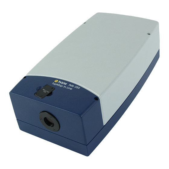
2 Introduction 2 Introduction System Overview The TMS-350 is a 3D topography measurement system for optical, non- contact acquisition of the structure of rough and also reflective surfaces. The TMS-350 measurement system is shown in the following figure: Monitor Sensor head Controller Figure 2.1: System components of the TMS-350... -
Page 14: Operating Principle
2 Introduction Operating Principle The TMS-350 is based on the principle of the white-light interferometer. In one interferometer arm the test sample is fixed in position, in the other there is a reference mirror. The reference mirror is moved with the aid of a piezo. A camera depicts the test sample. -
Page 15: First Steps
3 First Steps 3 First Steps Unpacking and Inspection INFORMATION The components marked with an (*) are described in detail in separate manuals! Always pay attention to these manuals, too! Unpacking The scope of supply includes the following components: TMS-I-350 interferometer •... - Page 16 3. In the case of a wrong delivery, damage or missing parts, immediately inform your local Polytec representative, stating the serial numbers of the instruments. The serial number can be found on the name plate. You will find the name plate on the instruments as well as on the inside cover of this manual.
-
Page 17: Control Elements, Displays And Connections
3 First Steps Control Elements, Displays and Connections 3.2.1 Controller Front view The front view of the controller is shown in the following figure. TMS-350 CONTROLLER POWER Figure 3.1: Front view of the controller POWER indicator lit up: ready to operate I/O mains switch... - Page 18 3 First Steps Back view The back view of the controller is shown in the following figure. PIEZO SENSOR WARNING ! Disconnet Mains before opening ACHTUNG ! Vor dem Öffnen Netzstecker ziehen POWER SUPPLY SENSOR -20...+120V Figure 3.2: Back view of the controller Cooling fan Warning label Name plate...
-
Page 19: Tms-I-350 Interferometer
3 First Steps 3.2.2 TMS-I-350 Interferometer Front view The front view of the interferometer is shown in the following figure. Figure 3.3: View of the interferometer Reference filter Filter to adjust the intensity of the reference light to the intensity of the object light. - Page 20 3 First Steps Back view The back view of the interferometer is shown in the following figure. SUPPLY SENSOR VIDEO PIEZO SENSOR Figure 3.4: Back view of the interferometer Name plate Plate with information on model, serial number, power specifications, etc. Holder desiccant cartridge PIEZO SENSOR connector (Sub-D jack with two coaxial applications) Connection for the piezo cable (Piezo) from the controller to control the piezo...
- Page 21 3 First Steps Bottom View The view from the bottom of the interferometer is shown in the following figure. Figure 3.5: Bottom view of the interferometer Fitting hole Mounting thread M6 Three mounting threads for the assembly of the interferometer on plane surfaces...
-
Page 22: Tms-W-350 Pc
3 First Steps 3.2.3 TMS-W-350 PC Front view The front view of the PC is shown in the following figure. The lockable front flap is shown transparently. RESET DATA MANAGEMENT SYSTEM POWER Figure 3.6: Front view of the PC Cooling fan Power L green: ready to operate HDD L... - Page 23 3 First Steps Back view The back view of the PC is shown in the following figure. MOUSE MOUSE KEYBOARD KEYBOARD Figure 3.7: Back view of the PC Cooling fan Name plate Plate with information on model, serial number, power specifications, etc. Warning label Monitor connection (HDMI jack) Connection is not used.
-
Page 24: Assembly
Check the devices for external damages such as scratches or the like. In the case of a wrong delivery, damage or missing parts, please inform your local Polytec representative immediately, stating the serial number of the devices. -
Page 25: Assembling Or Exchanging The Desiccant Cartridge
3 First Steps INFORMATION Keep the assembly instructions for all components in a safe place. 3.3.1 Assembling or Exchanging the Desiccant Cartridge ATTENTION! Damage caused by moisture! If you do not exchange the desiccant cartridge, moisture can condense on the optical components in the interferometer and can distort the measurement result. -
Page 26: Assembling The Interferometer
3 First Steps 3.3.2 Assembling the Interferometer INFORMATION Assemble the interferometer at one of the Polytec stands (refer to optional components S 3.1) or at the customer specific equipment. You will find ECTION the dimensions of the threaded and fitting holes in the technical drawing in HAPTER The mounting surface should be flat. - Page 27 » Check the contact pins before plugging in the cables. » Do not use any force when plugging in the cables. » Replace defective cables with new cables. » If necessary, contact your local Polytec representative. INFORMATION The system components are matched to each other and must not interchanged when using several systems.
- Page 28 3 First Steps Mains Connect all mains cables of the measurement system to the same earthed Connection wall outlet to avoid ground loops. Proceed as follows: 8. Connect up a mains cable to the TFT monitor and to a multiple socket. 9.
- Page 29 3 First Steps Interferometer TMS-I-350 SUPPLY SENSOR VIDEO PIEZO SENSOR Controller TMS-E-350 PIEZO SENSOR PIEZO SENSOR WARNING ! Disconnet Mains before opening ACHTUNG ! Vor dem Öffnen Netzstecker ziehen POWER SUPPLY SENSOR -20...+120V PC TMS-W-350 MOUSE MOUSE KEYBOARD KEYBOARD KEYBOARD MOUSE MONITOR Figure 3.8:...
-
Page 30: Functional Test
3 First Steps Functional Test Implementing a first functional test is described in the following. If the instrument does not perform as described, contact your local Polytec representative if required. Preparation To carry out a first functional test on the system, please proceed as follows: 1. -
Page 31: Measuring
4 Measuring 4 Measuring Data acquisition and storage for the TMS-350 is fully controlled via the software. A live video image of the object is displayed on the monitor and you can set up the area of interest on this video image. All acquisition properties are set in the software. -
Page 32: Making High-Precision Measurements
Reference A reference measurement which is balancing the curve in the field of view measurement made by Polytec is included in the TMS software on delivery. This reference measurement is automatically subtracted from your measurement after every measurement. Compensate for If you exchange the reference filter (refer to S 4.3), additional... -
Page 33: Reference Filter Exchange
4 Measuring 6. Make a measurement as described in your software manual. On the basis of this measurement you can estimate the size of measurement inaccuracies in later measurements, if you were not considered about them. 7. Save this measurement under a name of your choice. This measurement later serves as a reference measurement. - Page 34 4 Measuring On delivery a reference filter is always installed. To exchange the reference filter, please proceed as follows: 1. Use a Torx® screwdriver size TX 10 to remove the four Torx® screws (1) from the reference filter (refer to the following picture). 2.
- Page 35 4 Measuring 5. Hand-tighten the four Torx® screws of the reference filter again before you start operating the interferometer. INFORMATION Hand-tighten means: Tighten the screw firmly so that it can not undo itself. Do not use any excess force and avoid damaging the thread. INFORMATION If you have exchanged the reference filter, measurement inaccuracy may occur.
- Page 36 4 Measuring...
-
Page 37: Troubleshooting
Exchanging or retrospectively installing subassemblies may only be carried out by authorized service personnel of Polytec. If the faults or malfunctions can not be solved by the measures described here or if faults/malfunctions occur which are not mentioned here, please contact our service department. -
Page 38: Problems With The Interferometer
5 Troubleshooting Problems with the Interferometer No light is If no light is being emitted from the interferometer, please check if the supply emitted cable (Supply) between the controller and the interferometer has been installed and secured correctly. Problems with Set the measurement distance (approx. -
Page 39: Technical Specifications
6 Technical Specifications 6 Technical Specifications Harmonized Standards Applied Photobiological safety: IEC / EN 62471:2009-03 (Photobiological safety of lamps and lamp systems) Risk category: Electrical safety: IEC / EN 61010-1:2011-07 (Safety requirements for electrical equipment for measurement, control, and laboratory use) EMC: IEC / EN 61326-1:2006-10 (EMC requirements on Emission and Immunity -... -
Page 40: Tms-I-350 Interferometer
6 Technical Specifications TMS-I-350 Interferometer 6.3.1 General Data Piezo connection Voltage range for piezo control:– 20 VDC ... 120 VDC from the controller Ambient Conditions Operating temperature: + 5 °C … + 40 °C (41 °F… 104 °F) Storage temperature: –... - Page 41 6 Technical Specifications Dimensions +0.028 Æ 4 F8 +0.010 Æ 3.8 x 6 V 3 x M5-6H x 11/15.2 HELICOIL tangfree HELICOIL tangfree free running M6 x 6 free running M6 x 6 Æ 6.3 x 11.1 Æ 6.3 x 11.1 Center of AOI HELICOIL tangfree free running M6 x 6...
-
Page 42: Optics
6 Technical Specifications 6.3.2 Optics Characteristics Lateral measurement Optical limit resolution Model range µm Ø 21 mm (clip top and TMS-350 L bottom) TMS-350 M 13.68 x 10.31 mm TMS-350 S 17.9 6.43 x 4.84 mm Long-term Drift caused by Interferometer Warming up After switching on Long-term drift mm / min... - Page 43 6 Technical Specifications Typical step height measurements on a calibrated depth setting standard Nominal groove depth µm µm 0.15 0.35 Expanded uncertainty of measurement Relative measurement uncertainty 3.00 0.60 0.08 Repeatability µm 0.05 0.05 0.05 (standard deviation) Relative repeat precision 1.00 0.10 0.01...
-
Page 44: Tms-W-350 Pc
6 Technical Specifications TMS-W-350 PC Mains Connection Mains voltage: 100 … 240 VAC ± 10%, 50 / 60 Hz Power consumption: max. 525 VA Protection class: 1 (protective grounding) Ambient conditions Operating temperature: +5 °C…+40 °C (41 °F…104 °F) Storage temperature: −10 °C…+65 °C (14 °F…149 °F) Air humidity: max. -
Page 45: Appendix A: Tms-A-305 Calibration Set
A TMS-A-305 Calibration Set Appendix A: TMS-A-305 Calibration Set A.1 Summary The calibration set is used to check the basic measurement properties of the system. The calibration set consists of: Depth setting standard (calibration standard) • Calibration certificate • The depth setting standard is shown in F A.1. - Page 46 If you define just one standard, you will not have to select a standard later during calibration. INFORMATION To define depth setting standards, you need write permissions in the directory C:\Program Files\Polytec\ (Windows® 7). To define the depth setting standard, you proceed as follows: 1. Open the file Standards.xml...
- Page 47 A TMS-A-305 Calibration Set INFORMATION Some values have already been defined by default in the Standards.xml file. 2. Enter the name of the standard and from the calibration certificate, enter the depth, uncertainty and width for every groove and if applicable, delete any values which are not relevant (refer to F A.2).
- Page 48 A TMS-A-305 Calibration Set 5. Set up the area of interest as described in your software manual. Position the AOI in such a way that the first three grooves and a strip of the reference plane are included on the right and left (refer to F A.3).
- Page 49 A TMS-A-305 Calibration Set A.4 Evaluating the Measurement Result The measurement is analyzed using the CalibrationDataEvaluation add-in. The Add-in queries successively the used standard, and the ambient temperature as well as the device to be calibrated. You can avoid these queries by specifying the information in the file name of the measurement file that is to be analyzed.
- Page 50 A TMS-A-305 Calibration Set Figure A.6: Temperature dialog 3. Enter the measured ambient temperature and click OK. INFORMATION To apply the correct value for the ambient temperature, use a comma as the decimal separator. Select Device dialog appears. Figure A.7: Select Device dialog 4.
- Page 51 A TMS-A-305 Calibration Set Evaluation The Add-in calculates the depth of the grooves according to the evaluation method method defined in the calibration certificate: The ambient temperature determined is used to reduce the groove depth • to 20°C. This means that the groove depth is calculated which would result if the depth setting standard were measured at a temperature of 20°C.
- Page 52 A TMS-A-305 Calibration Set All calculation parameters for the expanded measurement uncertainty are regarded as being statistically independent. The expanded measurement uncertainty is calculated from the standard measurement uncertainty by multiplying with an expansion factor k = 2. With 95% probability, the deviation to be expected from a new measurement from a (true) value of the groove depth will be in the value range measurement value deviation ±...
-
Page 53: Appendix B: Declaration Of Conformity
B Declaration of Conformity Appendix B: Declaration of Conformity Figure B.1: Declaration of conformity for TMS-350... - Page 54 B Declaration of Conformity...
-
Page 55: Index
Index declaration of conformity depth setting standard define evaluate measurements evaluation method make measurements air humidity desiccant cartridge align, object assemble 3-11 ambient conditions exchange 3-11 controller specifications holder, at the interferometer PC (specifications) dimensions technical specifications controller, specifications weight assembly controller, specifications desiccant cartridge... - Page 56 interferometer, specifications operating state calibration indicator, on the controller housing operating temperature controller specifications mains connection PC(specifications) key switch, on the controller cabling 3-13 control elements, front view equipment label piezo control connector, at controller warning label, controller piezo control connector, at interferometer label plate piezo sensor connection, at controller name plate, at controller...
- Page 57 technical specifications controller interferometer troubleshooting unpack components unpacking video connection, at interferometer warm-up long-term drift of interferometer warning label at controller weight controller, specifications interferometer white-light interferometer wide range input controller...
- Page 59 Contact Polytec Europe Polytec Worldwide Germany (DE) ASEAN Countries Polytec GmbH Polytec South-East Asia Pte. Ltd. Headquarters Blk 4010, Ang Mo Kio Ave 10 Polytec-Platz 1–7 #06-06 TechPlace I 76337 Waldbronn Singapore 569626 Tel.: +49 7243 604-0 Tel.: +65 64510886...
Need help?
Do you have a question about the TMS-350 TopMap In.Line and is the answer not in the manual?
Questions and answers