
Related Manuals for Polytec OFV-3001


Summary of Contents for Polytec OFV-3001
- Page 1 ® Advanced Test Equipment Rentals www.atecorp.com 800-404-ATEC (2832) Title User Manual Laser Doppler Vibrometer Controller OFV-3001 Sensor Heads OFV-303 / -353 OFV-511 / -512...
- Page 2 Warranty and Service The warranty for this equipment complies with the regulations in our general terms and conditions in their respective valid version. This is conditional on the equipment being used as it is intended and as described in this manual.
-
Page 3: Table Of Contents
Contents Contents 1 Safety Information 1.1 Laser Safety ........................1-1 1.2 Laser Warning Labels ......................1-2 1.2.1 EC Countries ......................1-2 1.3 Laser Warning Labels ......................1-4 1.3.1 Non-EC Countries ..................... 1-4 1.4 Electrical Safety ........................1-6 2 Introduction 2.1 System Overview ........................ 2-1 2.2 Component Summary ...................... - Page 4 6.2 No Laser Beam........................6-2 6.3 No Measurement Signal ......................6-3 6.4 Checklist for Fault Diagnosis ....................6-5 6.4.1 Controller OFV-3001 with the Sensor Head OFV-303/-353 ........6-5 6.4.2 Controller OFV-3001 with the Sensor Head OFV-511/-512 .........6-6 7 Technical Specifications 7.1 Controller OFV-3001 ......................7-1 7.1.1 General Data ......................7-1...
-
Page 5: Safety Information
To ensure this, the following precautions have been taken: In general, Polytec equipment complies with the standards EN 60825-1 • (DIN VDE 0837) and CFR 1040.10 (US). -
Page 6: Laser Warning Labels
1 Safety Information 1.2 Laser Warning Labels 1.2.1 EC Countries Warning The laser warning labels for the sensor heads in EC countries are shown in labels figure 1.1. Label 2, 3 and 4 are affixed or enclosed in the language of the customer’s country. - Page 7 1 Safety Information Position The position of the laser warning labels in EC countries on the sensor head OFV-303/-353 is shown in figure 1.2. B e a m Figure 1.2: Position of the laser warning labels on the sensor head OFV-303/-353 in EC countries The position of the laser warning labels in EC countries on the sensor head OFV-511 resp.
-
Page 8: Laser Warning Labels
1 Safety Information 1.3 Laser Warning Labels 1.3.1 Non-EC Countries Warning labels The laser warning labels for the sensor heads in non-EC countries are shown figure 1.4. Their position on the sensor head OFV-303/-353 is shown in figure 1.5 and on the sensor head OFV-511 resp. OFV-512 in figure 1.6. - Page 9 1 Safety Information Position The position of the laser warning labels in non-EC countries on the sensor head OFV-303/-353 is shown in figure 1.5. B e a m Figure 1.5: Position of the laser warning labels on the sensor head OFV-303/-353 in non-EC countries The position of the laser warning labels in non-EC countries on the sensor head OFV-511 resp.
-
Page 10: Electrical Safety
1 Safety Information 1.4 Electrical Safety The vibrometer complies with the electrical safety class I. Electrical shock protection is achieved by a fully metallic housing connected to protective ground. Please pay attention to the following safety precautions when using the vibrometer: The vibrometer should only be connected via a three pin mains cable to •... -
Page 11: Introduction
The settings of the vibrometer are selected via the display of the controller or via PC interfaces. To display and analyze measurement results on a workstation, the Polytec Vibrometer Software (VibSoft) is available optionally. The software is described in a separate manual. -
Page 12: Component Summary
O V D - 3 0 O V D - 4 0 Figure 2.2: Compatibility of the controller OFV-3001 with sensor heads and decoders The modularity is achieved initially through strict separation of optics and electronics. Every decoder can be combined with every sensor head. -
Page 13: First Steps
3 First Steps 3 First Steps 3.1 Operating and Maintenance Requirements Operating The vibrometer can be operated in dry rooms under normal climate conditions environment (refer to chapter 7). In particular the optical components in the sensor head are sensitive to moisture, high temperatures, jolting and dirt. When the vibrometer is taken into operation after being stored somewhere cool, a sufficient acclimatization period should be allowed for before switching it on. -
Page 14: Unpacking And Inspection
2. Check the packaging for signs of unsuitable handling during transport. 3. In the case of a wrong delivery, damage or missing parts, inform your local Polytec representative immediately and give them the serial number of the sensor head and the controller. The identification labels can be found on the back of the instruments and also on the inside cover of this manual. -
Page 15: Control Elements Of The Vibrometer
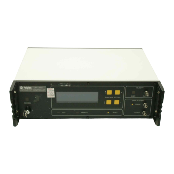
3 First Steps 3.3 Control Elements of the Vibrometer 3.3.1 Controller The front panel of the controller is shown in figure 3.1. V E L O C I T Y O . V 3 0 0 1 V I B R O M E T E R C O N T R O L L E R O V E R O U T P U T S E T T I N G... - Page 16 3 First Steps OVER - indicator for the velocity The L lights up when the output voltage exceeds either of the positive or negative full scale of the velocity measurement range. If it lights up permanently, the next highest velocity measurement range must be selected (refer also to section 4.2.2).
- Page 17 3 First Steps The back panel of the controller is shown in figure 3.2. G P I B / I E E E - 4 8 8 R S 2 3 2 I N T E R . E R O M E T E R S I G N A L R E M O T E .
- Page 18 3 First Steps Cooling Fan Caution ! This opening must always be kept free to ensure sufficient cooling. The distance from the wall should be at least 50 mm ! RS-232 - interface (Sub-D jack) Jack of the serial interface (refer to appendix...
-
Page 19: Sensor Head Ofv-303
3 First Steps 3.3.2 Sensor Head OFV-303 The back panel and the front panel of the sensor head OFV-303 are shown in figure 3.3. C O N T R O L L E R L A S E R A U T O M A N O . -
Page 20: Sensor Head Ofv-353
3 First Steps 3.3.3 Sensor Head OFV-353 The back panel and the front panel of the sensor head OFV-353 are shown in figure 3.4. B R A K E C O N T R O L L E R L A S E R O . -
Page 21: Sensor Head Ofv-511
3 First Steps 3.3.4 Sensor Head OFV-511 The front panel of the sensor head OFV-511 is shown in figure 3.5. S I G N A L O . V - 5 1 1 . I B E R I N T E R . E R O M E T E R L A S E R S T A N D B Y Figure 3.5: Front view of the sensor head OFV-511... - Page 22 3 First Steps Fiber optic cable Mini sensor (Diameter 10 mm) The mini sensor contains a lens to focus the laser beam. Exchange of the mini sensor with a fiber head is described in section B.3. Note ! Each mini sensor is exactly adjusted to its fiber. Never exchange the mini sensor with a mini sensor of another sensor head ! The back panel of the sensor head OFV-511 is shown in figure...
-
Page 23: Sensor Head Ofv-512
3 First Steps 3.3.5 Sensor Head OFV-512 The front panel of the sensor head OFV-512 is shown in figure 3.7. S I G N A L O . V - 5 1 2 . I B E R I N T E R . E R O M E T E R L A S E R S T A N D B Y Figure 3.7: Front view of the sensor head OFV-512... - Page 24 3 First Steps Mini sensors (Diameter 10 mm) Each mini sensor contains a lens to focus the laser beam. The mini sensor of the reference fiber is marked with a red dot. Exchange of the mini sensors with fiber heads is described in section B.3.
-
Page 25: Installation And Functional Test
3 First Steps 3.4 Installation and Functional Test 3.4.1 Vibrometer with Sensor Head OFV-303/-353 For the installation and an initial functional test of the vibrometer, proceed as follows: Preparing 1. Make sure that the key switch on the controller is in position O and the beam shutter on the sensor head is in position OFF. -
Page 26: Vibrometer With Sensor Head Ofv-511/-512
If your vibrometer does not perform as described above, read through the information on fault diagnosis provided in chapter 6 and, if necessary, contact your local Polytec representative. 3.4.2 Vibrometer with Sensor Head OFV-511/-512 For the installation and an initial functional test of the vibrometer, proceed as follows: Preparing 1. - Page 27 If the functional test has been successful you can now make measurements as described in chapter If your vibrometer does not perform as described above, read through the information on fault diagnosis provided in chapter 6 and, if necessary, contact your local Polytec representative. 3-15...
- Page 28 3 First Steps 3-16...
-
Page 29: Making Measurements
4 Making Measurements 4 Making Measurements 4.1 Start-up 4.1.1 Vibrometer with Sensor Head OFV-303/-353 Setup 1. Make sure that the key switch on the controller is in position O and the beam shutter on the sensor head are in position OFF. 2. -
Page 30: Vibrometer With Sensor Head Ofv-511/-512
4 Making Measurements 4.1.2 Vibrometer with Sensor Head OFV-511/-512 Setup 1. OFV-511: If desired, exchange the mini sensor with a fiber head (refer to section B.3). OFV-512: If desired, exchange both mini sensors with fiber heads (refer to section B.3) or for single point measurements exchange the mini sensor of the reference fiber with a reference head (refer to section 5.6 section... -
Page 31: Displaying The Output Signals
4 Making Measurements 4.1.3 Displaying the Output Signals To display the output signals, proceed as follows: Velocity 1. Connect an oscilloscope to the BNC jack VELOCITY OUTPUT on the signal front of the controller. With a suitable selected measurement range, the expected signal form should be visible at the VELOCITY OUTPUT. -
Page 32: Selecting Suitable Settings
4 Making Measurements 4.2 Selecting Suitable Settings 4.2.1 Velocity or Displacement Measurement ? The vibrometer can provide both velocity and displacement signals independently of each other. If the vibrometer is equipped with both velocity and displacement decoders, for many measurements a decision then has to be made on which is the optimal quantity to be measured. -
Page 33: Settings For Velocity Measurement
4 Making Measurements The situation for the velocity measurement is however quite different. For the same displacement amplitude but a higher frequency, the velocity amplitude of the required signal is a factor of 2π ⋅ f higher than the background vibration (refer to equation 4.1). - Page 34 4 Making Measurements in these ranges the permissible frequency decreases with increasing amplitude. If the condition is infringed upon, the signal is seriously distorted. In this case, a higher velocity measurement range has to be selected. In all velocity measurement ranges the L OVER on the front of the controller lights up if either the positive or negative end of range is exceeded.
- Page 35 4 Making Measurements In the upper frequency range, a constant velocity limit becomes effective again. To set the tracking filter, the range diagram in figure 4.1 can be summarized with the following rules of thumb: Below a particular velocity, no dynamic limits have to be taken into •...
- Page 36 Here they can prevent the FFT analyzer from overranging due to noise spikes. In the OFV-3001 controller, low pass filters with 3rd order Bessel characteristics are used. Characteristic of this type of filter is the phase linearity from the frequency zero up to the cutoff frequency i.e. the phase shift increases proportionally to the frequency.
- Page 37 4 Making Measurements The amplitude error caused by the filter can be determined from figure 4.4. A m p l i t u d e e r r o r / % - 1 0 - 1 5 - 2 0 - 2 5 - 3 0 0 .
-
Page 38: Settings For Displacement Measurement (Optional)
4 Making Measurements An additional time delay is caused by the velocity decoder. It depends on both velocity decoder and velocity measurement range and is approximately a few microseconds. The resulting overall phase shift ∆Φ can be estimated using the following simple equation: ∆Φ... - Page 39 4 Making Measurements x / m m 1 0 0 , 0 0 0 5 0 , 0 0 0 4 0 , 0 0 0 5 , 1 2 0 m m / V 2 5 , 0 0 0 1 0 , 0 0 0 1 , 2 8 0 m m / V 5 , 0 0 0...
- Page 40 4 Making Measurements Optimizing the The input of the vibrometer is equipped with an RF band-pass filter (refer to RF bandwidth section D.2). To achieve optimal adaptation to the FM-signal bandwidth, the RF bandwidth is automatically adjusted according to the velocity measurement range set.
- Page 41 4 Making Measurements Before making a measurement, the DC offset should therefore be reset to zero to make use of the full displacement measurement range. This can be done by pressing the CLEAR key on the front of the controller or by feeding an electrical pulse to the corresponding BNC jack.
-
Page 42: Optimal Stand-Off Distances For The Sensor Heads
4 Making Measurements 4.2.4 Optimal Stand-Off Distances for the Sensor Heads OFV-303/-353 The stand-off distance is measured from the front panel of the sensor head OFV-303/-353. The optimal stand-off distances are: ⋅ 232mm n 203mm , n = 0; 1; 2; ... i.e. -
Page 43: Operating The Vibrometer
5 Operating the Vibrometer 5 Operating the Vibrometer 5.1 Switching On and Off The vibrometer is switched on by turning the key switch on the front of the controller to position I. The L POWER above the key switch then lights up and shows that the controller is ready to operate. -
Page 44: Signal Level Display
5 Operating the Vibrometer 5.3 Signal Level Display The signal level display helps you to optimize the focus of the laser beam. The signal level is shown as a 20-part bar on the display of the controller (refer to section 5.9). - Page 45 5 Operating the Vibrometer Remote focusing To switch to remote focusing, you proceed as follows: 1. Press the knob AUTO / MAN into the front panel until it stops. 2. You can now focus remotely via the display of the controller as described in section 5.9.3 •...
-
Page 46: Exchanging The Front Lens
5 Operating the Vibrometer 5.5 Exchanging the Front Lens OFV-303/-353 By using different front lenses for the sensor head the vibrometer can be optimally adapted to the different ranges of stand-off distance. The standard front lens OFV-MR (mid range) is suitable for stand-off distances from 175 mm to over 10 m. -
Page 47: Making Single Point Measurements With The Sensor Head Ofv-512
5 Operating the Vibrometer 5.6 Making Single Point Measurements with the Sensor Head OFV-512 If single point measurements are carried out with the sensor head OFV-512, one of the two fibers must be terminated with a reference head. The reference head is marked with a red dot. -
Page 48: Transport Safety Mechanism (Only Ofv-511/-512)
5 Operating the Vibrometer 5.8 Transport Safety Mechanism (only OFV-511/-512) Caution ! Always activate the transport safety mechanism before moving the sensor head ! If the sensor head is being transported, the shock absorbing feet of the housing do not provide sufficient protection. For this reason, the interferometer must additionally be secured with a transport safety mechanism. -
Page 49: Operating The Vibrometer Via The Display Of The Controller
5 Operating the Vibrometer 5.9 Operating the Vibrometer via the Display of the Controller 5.9.1 Operating Philosophy The vibrometer is operated via a menu on the display of the controller using the keys FUNCTION and SETTING. The operating structure is mainly self- explanatory. -
Page 50: Organization Of The Menus
5 Operating the Vibrometer 5.9.2 Organization of the Menus The organization of the menus is shown in figure 5.3. S E T T I N G S I N T R O . O C U S C O N . I G Figure 5.3: Organization of the controller’s menus (menu FOCUS only with OFV-303) The two menus CONFIG and SETTINGS are available as standard. -
Page 51: The Individual Menus
5 Operating the Vibrometer 5.9.3 The Individual Menus Menu INTRO After switching on or RESET, the controller shows that it is ready to operate with the menu INTRO. It is not possible to change back to this menu as it does not have a control function. - Page 52 5 Operating the Vibrometer Menu In the menu SETTINGS the measurement ranges and filters are set. The SETTINGS contents of the menu depends on the decoders installed. The individual settings are described in the following. Tracking Filter In this line you can set the tracking filter. The input signal from the sensor head is pre-processed with the tracking filter.
-
Page 53: Setting Measurement Ranges And Filters
5 Operating the Vibrometer Menu FOCUS This menu is only available in vibrometers with the sensor head OFV-303. In (only with this menu, the motor which moves the front lens is controlled using the OFV-303) + and - keys. The movement of the motor is shown on the display of the controller with following symbols: <... - Page 54 5 Operating the Vibrometer 5-12...
-
Page 55: Fault Diagnosis
Please use the corresponding checklist in section 6.4, when you consult Polytec or your nearest representative. 6.1 General Tests If the vibrometer does not function properly, please first check the following: 1. Is the controller connected to the mains ? 2. -
Page 56: No Laser Beam
6 Fault Diagnosis 6.2 No Laser Beam If no laser beam is emitted, please check the following: 1. Is the connecting cable between the controller and the sensor head installed correctly ? 2. Are the jacks on the connecting cable screwed in securely ? OFV-303/-353 3. -
Page 57: No Measurement Signal
6 Fault Diagnosis 6.3 No Measurement Signal If the laser beam is emitted but there is no measurement signal, check the following: Signal level 1. Put a piece of reflective film at an optimal stand-off distance according to display the information given in section 4.2.4 in the beam path. - Page 58 6 Fault Diagnosis Figure 6.1: Pin configuration of the Sub-D jack INTERFEROMETER...
-
Page 59: Checklist For Fault Diagnosis
6 Fault Diagnosis 6.4 Checklist for Fault Diagnosis 6.4.1 Controller OFV-3001 with the Sensor Head OFV-303/-353 Serial Number Controller: Serial Number Sensor Head: OFV-303 OFV-353 The serial numbers can be found on the back of the instruments and also on the inside cover of this manual. -
Page 60: Controller Ofv-3001 With The Sensor Head Ofv-511/-512
6 Fault Diagnosis 6.4.2 Controller OFV-3001 with the Sensor Head OFV-511/-512 Serial Number Controller: Serial Number Sensor Head: OFV-511 OFV-512 The serial numbers can be found on the back of the instruments and also on the inside cover of this manual. -
Page 61: Technical Specifications
7 Technical Specifications 7 Technical Specifications 7.1 Controller OFV-3001 7.1.1 General Data 100 / 115 / 230 VAC ± 10%, 50 / 60 Hz, Mains voltage: adjustable at the back panel Power consumption: max. 150 VA Fuses: 1.0 A / slow-blow for 230 V 2.0 A / slow-blow for 100 / 115 V... -
Page 62: Low Pass Filter
7 Technical Specifications 7.1.3 Low Pass Filter For typical amplitude and phase frequency response, refer to section 4.2.2. Filter type: Bessel 3rd order Cutoff frequencies: 5 kHz, 20 kHz, 100 kHz, adjustable − 60 dB / dec = − 18 dB/ oct Frequency roll-off: Stop band rejection: >70 dB... - Page 63 7 Technical Specifications Calibration Accuracy Amplitude error Velocity Measurement @ T = (25 ± 5) °C in the temperature range decoder range (T = (77 ± 9)°F) 5°C ... 40°C (41°F... 104°F) ⁄ % of rms reading % of rms reading --------- - ±...
- Page 64 7 Technical Specifications Phase Frequency Response With the low pass filter switched off, the vibrometer behaves as a system of constant time delay i.e. the phase shift is proportional to the frequency. The phase shift depends, however, on the measurement range set. . Specific phase roll-off p Time delay t (typ.)
-
Page 65: Signal Voltage Output Displacement Output (Optional)
7 Technical Specifications 7.1.5 Signal Voltage Output DISPLACEMENT OUTPUT (optional) General Data Voltage swing: 16 V Output impedance: 50Ω Minimum load resistance: 10 kΩ (− 0.5 % additional error) Measurement Ranges Measurement Full scale Max. frequency Displacement Maximum range output Bandwidth for specified Resolution... -
Page 66: Sensor Head Ofv-303/-353
7 Technical Specifications Trigger (CLEAR Input) + 10 mV (typ.), rising edge Threshold: Hysteresis: 5 mV (typ.) ± 14 V Maximum input voltage: Pulse rate: 40 Hz ... 16 kHz Input impedance: > 0.5 kΩ (depending on the pulse frequency) 7.2 Sensor Head OFV-303/-353 7.2.1 General Data Laser type:... - Page 67 7 Technical Specifications C O N T R O L L E R L A S E R O . . E M I S S I O N 1 2 0 Figure 7.1: Rear view and bottom view of the sensor head OFV-303/-353 (dimensions not specified are given in mm)
-
Page 68: Sensor Head Ofv-511/-512
7 Technical Specifications 7.3 Sensor Head OFV-511/-512 7.3.1 General Data Laser type: helium neon Wavelength: 633 nm Cavity length: 203 mm Power consumption: ca. 15 W Output center frequency: 40 MHz + 0°C... + 40°C (32°F... 104°F) Operating temperature: − 15°C ... + 65°C (5°F... 149°F) Storage temperature: Relative humidity: max. - Page 69 7 Technical Specifications Maxima of Visibility Sensor head Maxima of visibility 135 mm + n · 203 mm, n = 0; 1; 2; ... OFV-511 0 mm + n · 203 mm, n = 0; 1; 2; ... OFV-512 (two point measurement) 63 mm + n ·...
- Page 70 7 Technical Specifications Dimensions of the Side Exit Heads OFV-C-102 2 5 7 . 5 1 5 7 . 5 9 6 . 5 c a . 1 3 0 Figure 7.2: View of the side exit head OFV-C-102 (dimensions not specified are given in mm) OFV-C-110 2 5 7 .
-
Page 71: Appendix A: Optional Accessories For The Sensor Head Ofv-303/-353
A Optional Accessories for the Sensor Head OFV-303/-353 Appendix A: Optional Accessories for the Sensor Head OFV-303/-353 A.1 Hand Terminal OFV-310 With the hand terminal OFV-310 shown in figure A.1, the laser beam of the sensor head OFV-303 can be remotely focused. S I G N A L . - Page 72 A Optional Accessories for the Sensor Head OFV-303/-353 A.2 Side Exit Adapter OFV-C-128 Using the side exit adapter OFV-C-128 the laser beam can be deflected by 90 degrees and allows thus the use of the sensor head OFV-303/-353 on otherwise inaccessible parts. The telescopic front tube can be rotated by 360 degrees and it can be extended from 297 mm to 377 mm.
- Page 73 A Optional Accessories for the Sensor Head OFV-303/-353 A.3 Tip-Tilt Stage OFV-P5 with Optional Targeting Telescope The OFV-P5 is a tip-tilt assembly which allows fine positioning of the laser beam when working at long distances. With this unit the laser beam can be tilted ±...
- Page 74 A Optional Accessories for the Sensor Head OFV-303/-353 4 2 6 1 / 4 " 2 x M 6 M o u n t i n g P l a t e f o r M a n f r o t t o - T r i p o d 1 6 0 2 8 0 O .
-
Page 75: Appendix B: Optional Accessories For The Sensor Head Ofv-511/-512
B Optional Accessories for the Sensor Head OFV-511/-512 Appendix B: Optional Accessories for the Sensor Head OFV-511/-512 B.1 Reference Head OFV-152 If single point measurements are carried out with the sensor head OFV-512, one of the two fibers must be terminated with a reference head. The reference head is marked with a red dot. - Page 76 B Optional Accessories for the Sensor Head OFV-511/-512 Assembly You will need an adapter and a swivel nut to mount the reference head OFV-152. You will find them both in the tool kit for the vibrometer. The assembly of the reference head OFV-152 is shown in figure B.2.
- Page 77 B Optional Accessories for the Sensor Head OFV-511/-512 B.2 Side Exit Head OFV-C-102 and OFV-C-110 The side exit heads have a mirror and a side exit window. The laser beam can thus be deflected by 90 degrees from the output direction from the fiber. The following side exit heads are available for the sensor head OFV-511/-512: OFV-C-102, 90°...
- Page 78 B Optional Accessories for the Sensor Head OFV-511/-512 B.3 Fiber Heads The following fiber heads are available for the sensor head OFV-511/-512: OFV-101 • OFV-102 standard fiber head • OFV-130-3 for beam diameter 3 µm • OFV-130-5 for beam diameter 5 µm •...
- Page 79 B Optional Accessories for the Sensor Head OFV-511/-512 B.4 Flexible Arm OFV-039 The flexible arm OFV-039 is a mount device for the mini sensor of the sensor head OFV-511/-512. The mini sensor can thus be easily positioned in places which are difficult to access. The heavy steel base ensures that it stands securely and if required the steel base can be screwed onto the surface beneath via the drilled mounting holes (refer to figure...
- Page 80 B Optional Accessories for the Sensor Head OFV-511/-512 2 x 4 5 ° 0 . 5 0 C o u n t e r s i n k i n g D I N 7 4 K m 6 ( 3 x ) A - A Figure B.5: Base plate for the flexible arm OFV-039 (dimensions not specified are given in...
-
Page 81: Appendix C: Basics Of The Measurement Procedure
C Basics of the Measurement Procedure Appendix C: Basics of the Measurement Procedure C.1 Theory of Interferometric Velocity and Displacement Measurement Optical interference can be observed when two coherent light beams are made to coincide. The resulting intensity e.g. on a photo detector varies with the phase difference ∆ϕ... - Page 82 C Basics of the Measurement Procedure C.2 Optical Configuration in the Sensor Head OFV-303/-353 In Polytec’s vibrometers, the velocity and displacement measurement is carried out using a modified Mach-Zehnder interferometer. The optical configuration in the sensor head OFV-303/-353 is shown schematically in figure C.1.
- Page 83 C Basics of the Measurement Procedure C.3 Optical Configuration in the Sensor Head OFV-511/-512 In Polytec’s vibrometers, the velocity and displacement measurement is carried out using a modified Mach-Zehnder interferometer. OFV-511 The optical configuration in the sensor head OFV-511 is shown schematically figure C.2.
- Page 84 C Basics of the Measurement Procedure OFV-512 The optical configuration of the sensor head OFV-512 is shown schematically figure C.3. . i b e r H e a d L a s e r B S 1 B S 2 C o u p l e r .
-
Page 85: Appendix D: Functional Description Of The Controller
D e m o d u l a t o r I I Figure D.1: Block diagram of the controller OFV-3001 The RF signal from the sensor head (sensor input) initially passes the functional block signal conditioning where it is pre-processed to optimally drive the following blocks. - Page 86 D Functional Description of the Controller The velocity decoder is followed by a low pass filter which suppresses spurious RF components and limits the bandwidth of the output signal to reduce background noise. Via the system control, various cutoff frequencies can be set for the low pass filter.
- Page 87 D Functional Description of the Controller Drop-out Drop-out reduction via the tracking filter plays a very important role in optical reduction via signal processing. The light scattered back from the object has a speckled the tracking nature i.e. at any instant the detector sees a light or a dark speckle. The low filter signal amplitude of the dark speckle can lead to loss of signal, so-called drop- outs.
- Page 88 D Functional Description of the Controller Down-mixing Down-mixing of the frequency in the input section is required to convert the of the carrier frequency of the FM signal from 40 MHz originally to lower frequency intermediate frequencies. With these intermediate frequencies, the velocity decoder can work optimally in the individual measurement ranges.
- Page 89 D Functional Description of the Controller D.4 Velocity Decoder D.4.1 The Various Velocity Decoders Technically it is just about impossible to attain all desirable and realizable characteristics of the velocity decoder in a single universal subassembly. The modular concept of the controller thus permits the use of two different velocity decoders which can be installed simultaneously.
- Page 90 The filters are adjusted via the system control. In the OFV-3001 controller low pass filters with 3rd order Bessel characteristics are used. Bessel filters have the advantage of a linear phase response and thus optimal transmission behavior for pulses.
- Page 91 D.5.1 Mode of Operation The phase of the interferometer signal is the carrier of the displacement information. To be directionally sensitive, Polytec’s vibrometers work on the heterodyne principle i.e. the phase is modulated onto a carrier signal. The information required thus rides on the phase difference between the driver signal for the Bragg cell and the modulated signal at the photo detector.
- Page 92 D Functional Description of the Controller D.5.3 Operating Principle The functional structure of the displacement decoder is shown schematically figure D.3. O s c i l l a t o r r e f D / A C o n v e r t e r L o w P a s s D I R E C T I O N 1 2 b i t...
- Page 93 D Functional Description of the Controller however, that due to the phase multiplication both the original bandwidth of the modulated signal and the pulse frequency at the counter are increased. The technical limits in the direct counting mode are reached at a velocity of 10 m / s, however in the high resolution ranges this value decreases approximately by the multiplier (refer also to section...
- Page 94 D Functional Description of the Controller D-10...
-
Page 95: Appendix E: Interface Operation Rs-232 And Ieee-488 / Gpib
E Interface Operation RS-232 and IEEE-488 / GPIB Appendix E: Interface Operation RS-232 and IEEE-488 / GPIB E.1 Configuration of the Interfaces Using the interfaces RS-232 and IEEE-488 / GPIB the following commands are supported: query and change the settings of the controller •... - Page 96 E Interface Operation RS-232 and IEEE-488 / GPIB RENDCL Sets the status REMOTE and loads the following initialization settings: TRACK = 1 (OFF) ⁄ VELO (1,000 --------- - FILT (OFF) (5,120 µm/ V) AMPL Loads the initialization settings (see above) without changing the current REM status i.e.
- Page 97 E Interface Operation RS-232 and IEEE-488 / GPIB E.2.4 Measurement Range Setting and Query All transmissions from and to the controller are terminated with the ASCII character LF (Line Feed) i.e. decimal 10, hexadecimal 0x0a. In the examples given here, this character is described with the escape sequence "\n" according to its presentation in the programming language C.
- Page 98 E Interface Operation RS-232 and IEEE-488 / GPIB Displacement Decoder Answer with Command Description Answer ECHOON AMPL? Queries the set measurement Range number AMPL1 ... range (ASCII character) AMPL7 1 ... 7 (refer to table below) AMPL1 ... Sets the corresponding AMPL1 ...
- Page 99 E Interface Operation RS-232 and IEEE-488 / GPIB E.2.5 Filter Setting and Query Tracking Filter Answer with Command Description Answer ECHOON TRACK? Queries the setting of the tracking 1 = OFF TRACK1 filter 3 = SLOW TRACK3 4 = FAST TRACK4 TRACK1 Sets the tracking filter to this...
- Page 100 E Interface Operation RS-232 and IEEE-488 / GPIB E.2.6 Signal Level Query and Motor Control Commands Signal Level Answer with Command Description Answer ECHOON Queries the optical signal level 0 = no level LEV0 ... LEV40 1 = level 1 2 = level 1 and 2 3 = level 1 to 3 40 = level 1 to 40...
- Page 101 E-mail: info-vi@polytec.de Internet: http://www.polytec.de Internet: http://www.polytec.com POLYTEC Physik Instrumente France (F) Vertriebs- und Beratungsbüro Berlin Polytec PI / RMP S.A. Schwarzschildstraße 1 32, rue Délizy D-12489 Berlin F-93694 Pantin Cédex Tel.: (030) 6392-5140 Tel.: (+33) 1-4810 39 30 Fax:...
Need help?
Do you have a question about the OFV-3001 and is the answer not in the manual?
Questions and answers