
Related Manuals for Polytec PSV-500


Summary of Contents for Polytec PSV-500
- Page 1 Title Hardware Manual Polytec Scanning Vibrometer P S V- 5 0 0 Scanning Head PSV-I-500 Front-End PSV-F-500-HM Junction Box PSV-E-530 PSV-W-500-M For the PSV-500-HM System...
- Page 2 Warranty and Service The warranty for this equipment complies with the regulations in our general terms and conditions in their respective valid version. This is conditional on the equipment being used as intended and as described in this manual. The warranty does not apply to damage caused by incorrect usage, external mechanical influences or by not keeping to the operating conditions.
-
Page 3: Table Of Contents
Contents Contents 1 Safety Information 1.1 General Safety Information ....................1-1 1.2 Information on Laser Safety ....................1-2 1.2.1 Safety Information ....................1-2 1.2.2 Safety Precautions ....................1-3 1.2.3 Laser Warning Labels ....................1-4 1.3 Information on Electrical Safety ..................1-5 1.3.1 Safety Information .................... - Page 4 Contents 4.3 Setting up Optimal Stand-off Distances ................4-5 4.3.1 Relation between Stand-Off Distance and Visibility Maximum ........4-5 4.3.2 Optimal Stand-Off Distances ..................4-6 4.3.3 Optimal Stand-off Distances with PSV-A-560 CoherenceOptimizer (optional) ....4-7 5 Operating the PSV 5.1 Switching On and Off ......................5-1 5.2 Blocking the Laser Beam ....................5-1 5.3 Indicating Laser Activity ......................5-2 5.4 Setting up the Scanning Head .....................5-2...
-
Page 5: Safety Information
1 Safety Information 1 Safety Information General Safety Information Notes Please read this manual before using the instrument. It will provide you with important information on using the instrument and on safety. This allows you to protect yourself and prevents any damage being done to the instrument. Pay particular attention to the basic safety information in 1 and the CHAPTER... -
Page 6: Information On Laser Safety
General The protective measures described in the following support compliance with the safety standards for Laser Class 2: Polytec instruments generally comply with the standards IEC and • EN 60825-1 respectively US 21 CFR 1040.10 and 1040.11 except for deviations pursuant to Laser Notice no. 50, dated 24 June 2007. -
Page 7: Safety Precautions
1 Safety Information 1.2.2 Safety Precautions Pay attention to the following safety precautions when using the instrument: Only qualified and fully trained persons should be entrusted with setting • up the instrument, adjusting and operating it ! Avoid looking directly into the laser beam with the naked eye or with the •... -
Page 8: Laser Warning Labels
1 Safety Information 1.2.3 Laser Warning Labels Warning labels The laser warning labels are shown in the following figure. For countries in the European Union (EU), labels 2 and 3 are affixed in the language spoken in the customer's country (see right-hand-side). Figure 1.1: Laser warning labels Position... -
Page 9: Information On Electrical Safety
1 Safety Information Information on Electrical Safety 1.3.1 Safety Information The instrument complies with the electrical protection class 1 in accordance with the EU Directive 2006 / 95 / EC (Low Voltage Directive). With correct mains connection and intended use, exposure to electric current is prevented by the closed, grounded metal housing. - Page 10 1 Safety Information...
-
Page 11: Introduction
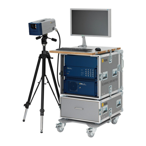
NT SY ST Figure 2.1: System components of the PSV-500-HM Polytec Scanning Vibrometers consist of the basic components optics (scanning head), electronics (front-end), junction box and control (data management system). The components are adapted to suit the intended area of application and can be customized by adding accessories and upgrading the hardware. -
Page 12: Signal Flow Between The System Components
Here, the velocity information is extracted from the signal. You can run the system either as a PSV-500-H or as a PSV-500-M. To do so, when starting the software select the corresponding data acquisition... -
Page 13: Decoder
2 Introduction 2.2.2 Decoder In the PSV-500-HM the digital velocity decoder DV-04 is used. It enables very precise and high-resolution acquisition of vibrations. With the PSV-500-H, the decoder signals are directly transmitted digitally to the PC. With the PSV-500-M the signals are converted into analog signals and transmitted to the data acquisition board of the PC. - Page 14 2 Introduction...
-
Page 15: First Steps
3 First Steps 3 First Steps NOTE! The components marked with an (*) are described in detail in separate manuals ! Unpacking and Inspection CAUTION! Misalignment caused by shock ! Protect the unpacked scanning heads from hard shocks ! Unpacking The scope of supply includes the following components: PSV-F-500-HM front-end •... -
Page 16: Operating And Maintenance Requirements
3. In the case of a wrong delivery, damage or missing parts, immediately inform your local Polytec representative, stating the serial number of the instrument. The serial number can be found on the identification label. - Page 17 Hardware or software components which do not belong to the system can other damage the system or adversely affect the way the Polytec software components functions. Using them will result in the loss of warranty. If you want to install such components, contact Polytec.
-
Page 18: Psv-F-500-Hm Front-End
The connections on the front are only used for the operation as an H system (exception: AUX IN and AUX OUT). The front view of the front-end is shown in the following figure. REF1 REF2 REF3 REF4 PSV-500 IEPE IEPE IEPE IEPE VIBROMETER FRONT-END ANALOG IN... - Page 19 3 First Steps SIGNAL 1 generator output (BNC jack) Analog voltage output for the signal of the function generator SIGNAL 2 to SIGNAL 4 generator outputs (BNC jacks) There are three additional analog voltage outputs available for the signals of the function generator.
-
Page 20: Psv-E-530 Junction Box
3 First Steps 3.3.2 PSV-E-530 Junction Box The PSV-E-530 junction box is only used for the operation as an M system. Front view The front view of the junction box is shown in the following figure. REF 1 REF 3 TRIG IN SYNC SIGNAL... -
Page 21: Psv-W-500-M Pc
3 First Steps REF 1 signal output (BNC jack) Connection for the AI_1 line of the ACQ HM acquisition cable from the PC Connection for cable shielding (blade connector) Connection for the shielding line of the ACQ HM acquisition cable 3.3.3 PSV-W-500-M PC Front view... - Page 22 3 First Steps Lock with key in the front flap Front flap is lockable Back view The back view of the PC is shown in . The order of the plug-in boards may vary from that shown in the figure. MOUSE KEYBOARD 20 19...
- Page 23 3 First Steps ACQUISITION connector (SCSI-II-type) PSV-500-M: Connection for the acquisition cable (ACQ HM) from the front-end and from the PSV-E-530 junction box to transmit the measurement and trigger signals 10 GENERATOR connections of the generator board (SMB jacks) PSV-500-M: Connections for the BNC-SMB connecting cables to the PSV-E-530 junction box to transmit the signals of the function generator You will find a description of the connections of the generator board in the following section.
- Page 24 3 First Steps Generator board The connections of the Spectrum M2i.6030 generator board are shown in the following figure. Ch 0 Figure 3.7: View of the generator board Ck clock input (SMB jack) Input for the clock signal (Clock) to synchronize the generator board with the data acquisition board Trg signal input (SMB jack) Input is not used !
-
Page 25: Psv-I-500 Scanning Head
3 First Steps 3.3.4 PSV-I-500 Scanning Head Front view The front view of the scanning head is shown in the following figure. Figure 3.8: Front view of the scanning head Mounting thread for the PSV-A-410 close-up unit (not for PSV-3D) or for the PSV-A-525 protective window Front lens of the video camera with M37 mounting thread for the filters and lenses (only PSV-I-500) - Page 26 3 First Steps Back view The back view of the scanning head is shown in the following figure. Polytec PSV-500 SCANNING HEAD LASER SIGNAL 10-32 OPTION UNF-2B Figure 3.9: Back view of the scanning head Transport handle SIGNAL level display Measure for the light scattered back form the measurement surface The signal level display is deactivated when the geometry laser (Geo-Laser) is activated.
- Page 27 3 First Steps Bottom view The bottom view of the scanning head is shown in the following figure. Figure 3.10: Bottom view of the scanning head M6 mounting threads For mounting or adapter plate, e.g. for mounting on a tripod system Mounting threads for quick release plate E.g.
-
Page 28: Assembly
! Check the devices for external damages such as scratches or the like. In the case of a wrong delivery, damage or missing parts, please inform your local Polytec representative immediately, stating the serial number of the devices. -
Page 29: Scanning Head
3 First Steps 3.4.1 Scanning Head The scanning head is mounted on a light duty tripod with fluid head (VIB-A-T02). The scanning head mounted on the light duty tripod with fluid head is shown in the following figure. Figure 3.11: Scanning head mounted on the light duty tripod with fluid head CAUTION! Risk of falling caused by loose locking mechanisms and screws ! Loose screws may cause the tripod to be unstable and possibly collapse. -
Page 30: Vib-A-T02 Light Duty Tripod With Fluid Head
3 First Steps 3.4.2 VIB-A-T02 Light Duty Tripod with Fluid Head You can assemble the scanning head on the VIB-A-T02 tripod with fluid head. To do so, proceed as follows: 1. Assemble the tripod as described in the assembly instructions provided by the manufacturer MANFROTTO. -
Page 31: Psv-A-013 System Cabinet
3 First Steps 3.4.3 PSV-A-013 System Cabinet The PSV-A-013 system cabinet is supplied with all system components assembled and cabled. Unpack the system cabinet as follows: 1. Remove the lashing straps using a suitable tool, e.g. a pair of scissors. 2. - Page 32 3 First Steps Build up the system cabinet. To do so, proceed as follows: 1. Carefully remove the cover of the system cabinet by loosening the wing screws and releasing the locking hooks (refer to 3.13 on the left). FIGURE 2.
- Page 33 3 First Steps Unfold the To have more legroom when working on the system, you can move the work workplate plate up to 12 cm forwards. To do so, proceed as follows: 1. Fold in the screen. CAUTION! Risk of tilting caused by mishandling ! Fold in the screen before unfixing the locking hooks and moving the workplate.
-
Page 34: Cabling
FIGURE 3.15. Secure the connections appropriately. FIGURE Should any cabling problems occur, contact your local Polytec representative. CAUTION! Damage of the instruments caused by short-circuit ! Always connect all components to each other before plugging in the mains cables ! - Page 35 3 First Steps Junction box to 6. Connect a BNC-SMB connecting cable to the Ch0 BNC jack on the back of the junction box and to the GENERATOR (Ch0) SMB jack on the back of the PC. 7. Connect a BNC-SMB connecting cable to the D0 BNC jack on the back of the junction box and to the GENERATOR (D0) SMB jack on the back of the PC.
- Page 36 3 First Steps SCANKOPF PSV-I-500 FRONTEND PSV-F-500-HM ANSCHLUSSBOX PSV-E-530 Figure 3.14: Cabling of the front-end with the PC, the junction box and the scanning head 3-22...
- Page 37 13. Screw a compensation sensor into the 10-32 UNF-2B thread on the back sensor of the scanning head and connect it to a REF BNC jack on the front of the front-end. Polytec PSV-500 SCANNING HEAD LASER SIGNAL 10-32 OPTION...
-
Page 38: Connecting The Signals (M System)
3 First Steps 3.5.2 Connecting the Signals (M System) Reference 1. Connect up the reference signal to the REF 1 BNC jack on the front of the signal junction box. 2. If required, you can connect up to two additional reference signals to the REF 2 to REF 3 BNC jacks on the front of the junction box. -
Page 39: Connecting The Signals (H System)
3 First Steps 3.5.3 Connecting the Signals (H System) Reference 1. Connect up the reference signal to the REF 1 BNC jack on the front of the signal front-end. 2. If required, you can connect up to seven additional reference signals to the REF 2 to REF 8 BNC jacks on the front of the front-end. -
Page 40: Connecting The Mains Cables
The implementation of a first functional test is described in the following. If the instrument does not perform as described, read through the information on fault diagnosis in 6 and if required, contact your local Polytec CHAPTER representative. For an initial functional test, proceed as follows: Prepare 1. - Page 41 3 First Steps Switch on 5. Switch on the front-end by turning the key switch to position I. The POWER L on the front of the front-end lights up. If all the connecting cables are correctly installed, then the LASER L on the scanning head lights up.
- Page 42 3 First Steps Direction The following direction convention applies to the output signals: convention A movement towards the scanning head is seen as being positive. In this case the velocity output provides a positive signal. 3-28...
-
Page 43: Making Measurements
Damage to the system caused by heat accumulation ! Remove the covers of the system cabinet before operating the instruments in the system cabinet. NOTE! When starting the software, select the measurement system: Ethernet for PSV-500-H PCI-6110 for PSV-500-M To make a measurement, proceed as follows: Setup 1. -
Page 44: Selecting Suitable Settings
4 Making Measurements 7. Start the data acquisition as described in your software manual. NOTE! Before working with laser light, read the information on laser safety in 1.2 ! SECTION 8. Open the beam shutter on the front of the scanning head. The laser beam is now emitted from the scanning head. -
Page 45: Tracking Filter
4 Making Measurements When there is an extremely weak optical signal, a permanently Overrange display can be caused by noise due to the system. If switching on the tracking filter (refer to 4.2.2) does not remedy this problem, check the SECTION following: Have you focused the laser optimally? - Page 46 4 Making Measurements For the tracking filter settings, you can use the following rules of thumb: Use the tracking filter to improve the signal noise if the optical signal is • weak. If you have a good optical signal, it is not possible for the tracking filter to improve the signal-to-noise ratio for physical reasons.
-
Page 47: Setting Up Optimal Stand-Off Distances
4 Making Measurements Setting up Optimal Stand-Off Distances 4.3.1 Relation between Stand-Off Distance and Visibility Maximum Visibility The signal-to-noise ratio (SNR) of the data is primarily determined by the maxima signal level. The higher the signal level, the higher the signal-to-noise ratio. The height of the signal level depends on the surface properties of the object, on random speckle effects, and on the stand-off distance. -
Page 48: Optimal Stand-Off Distances
4 Making Measurements Stand-off The stand-off distance is measured from the front of the scanning head (refer distance to the following figure). Figure 4.2: Measuring the stand-off distance 4.3.2 Optimal Stand-Off Distances The relation between stand-off distance and signal level is shown in the following figure. -
Page 49: Optimal Stand-Off Distances With Psv-A-560 Coherenceoptimizer (Optional)
4 Making Measurements Optimal stand-off distance = 141 mm + (n · l) mm n … 0, 1, 2, … l … 204 mm ± 1 mm This means the optimal stand-off distances are: 141 mm, 345 mm, 549 mm, 753 mm, 957 mm, etc. - Page 50 4 Making Measurements...
-
Page 51: Operating The Psv
5 Operating the PSV 5 Operating the PSV In the software manual, you will find the following detailed information on how to control the system via the software: Setting the optics • Aligning coordinates • Defining and editing scan points •... -
Page 52: Indicating Laser Activity
5 Operating the PSV Indicating Laser Activity Each scanning head is equipped with a LASER L which indicates the activity of the laser. The LASER L is on the back of the scanning head. The LASER L is lit when the laser is switched on (key switch on the front of the front-end in position I). -
Page 53: Fault Diagnosis
Tampering with the instruments in any way is not necessary when using the equipment as intended and will invalidate the warranty. Exchanging or retrospectively installing modules may only be carried out by authorized service personnel of Polytec. If the faults or malfunctions can not be solved by the measures described here or if faults / malfunctions occur which are not mentioned here, please contact our service department. -
Page 54: Problems With The Laser
1. Exit the software. 2. Start the Polytec Configuration Tool with administrator rights. To do so, click Start > Programs > Polytec Configuration Tool 1.0 > Polytec Configuration Tool. The application window Polytec Configuration Tool appears. 3. Click Configure. -
Page 55: Highly Fluctuating Signal Level Display
6 Fault Diagnosis 6.2.2 Highly Fluctuating Signal Level Display If the signal level display on the back of the scanning head or in the software periodically fluctuates greatly, proceed as follows: 1. If your system is equipped with the optional PSV-A-560 CoherenceOptimizer, wait until the status of the CoherenceOptimizer state is shown as being stable in the software. - Page 56 6 Fault Diagnosis Vibrometer Check the vibrometer signals of the front-end. To do so, proceed as follows: signal Refer also to the software manual. 1. Set the 100 mm / s measurement range. 2. Put a matt white test surface such as a piece of paper approximately 50 cm away from the front of the scanning head in the beam path.
-
Page 57: Technical Specifications
7 Technical Specifications 7 Technical Specifications Harmonized Standards Applied Laser safety: IEC / EN 60825-1:2008-05 (Safety of Laser Products, complies to US 21 CFR 1040.10 and 1040.11 except for deviations pursuant to Laser Notice no. 50, dated 24 June 2007) Electrical safety: IEC / EN 61010-1:2011-07 (Safety requirements for electrical equipment for... -
Page 58: Signal Inputs And Outputs
7 Technical Specifications Housing Protection rating: IP 20 Dimensions (w x h x d): Without angle brackets 450 mm x 150 mm x 380 mm (19", 84 HP / 3 U) With angle brackets 485 mm x 150 mm x 380 mm (19", 84 HP / 3 U) Weight: 10 kg Calibration... -
Page 59: Metrological Properties
7 Technical Specifications SYNC, AUX OUT Compatibility: TTL / CMOS Output voltage HIGH: min. 2.5 V (I = 5 mA) Output voltage LOW: max. 0.5 V (I = 2 mA) Output resistance: 100 Ω 7.2.3 Metrological Properties Table 7.1: Metrological properties of the DV-04 decoder (1 of 4) Full scale value (peak) mm / s Scaling of analog output... - Page 60 7 Technical Specifications Table 7.2: Metrological properties of the DV-04 decoder (2 of 4) Full scale value (peak) mm / s Scaling of analog output 12.5 Frequency range Max. acceleration 2 560 16 000 Frequency response 0.0 Hz … 100 kHz ±...
- Page 61 7 Technical Specifications Table 7.3: Metrological properties of the DV-04 decoder (3 of 4) Full scale value (peak) mm / s Scaling of analog output Frequency range 1 000 2 000 2 000 Max. acceleration 64 000 256 000 640 000 Frequency response 0.0 Hz …...
- Page 62 7 Technical Specifications Table 7.4: Metrological properties of the DV-04 decoder (4 of 4) Full scale value (peak) 1 000 2 000 5 000 10 000 mm / s Scaling of analog output 1 250 2 500 Frequency range 2 000 2 000 2 000 2 000...
-
Page 63: Data Acquisition (H System)
7 Technical Specifications 7.2.4 Data Acquisition (H System) PSV-500-HM (H system) Data acquisition PSV-F-500-HM Reference channels 4 (8) Maximum bandwidth 100 kHz Function generator PSV-F-500-HM Output channels Maximum bandwidth 100 kHz The specifications in brackets are available as an option. -
Page 64: Data Acquisition (M System)
7 Technical Specifications 7.3.3 Data Acquisition (M System) PSV-500-HM (M system) Data acquisition PCI-6110 Reference channels Maximum bandwidth 1 MHz (2 MHz) Function generator M2i.6030 Output channels Maximum bandwidth 1 MHz (2 MHz) The designations in brackets are available as an option. -
Page 65: Psv-I-500 Scanning Head
7 Technical Specifications SIGNAL Output voltage: max. ± 10 V at high-impedance load max. ± 5 V into 50 Ω Output current: max. ± 100 mA Output impedance: 50 Ω Short-circuit protection: permanently short-circuit proof SYNC Compatibility: TTL / CMOS Output voltage HIGH: min. - Page 66 7 Technical Specifications Housing Protection rating: IP 0 IP 40 (beam shutter closed or PSV-A-525 protective window or PSV-A-410 close-up unit mounted) Dimensions: refer to the following figure Weight: 9.2 kg (including geometry scan unit and CoherenceOptimizer) 7-10...
- Page 67 7 Technical Specifications Dimensions Ø4 Ø4 Figure 7.1: Dimensions of the scanning head (Dimensions not specified are given in mm.) 7-11...
-
Page 68: Optics
7 Technical Specifications 7.5.2 Optics Focal length (nominal): 70 mm Minimum stand-off distance: 125 mm Spot diameter Depth of focus Stand-off distance Aperture diameter (1 / e , typ.) (typ.) [mm] [µm] [mm] [mm] 0.48 1 000 10.4 With each additional meter stand-off distance 85µm are added to the spot diameter. Measured from the front of the scanning head For 3 dB signal reduction At the front of the scanning head... -
Page 69: Scanner
7 Technical Specifications Signal Level Depending on Surface and Stand-Off Distance Figure 7.3: Typical signal level range depending on the stand-off distance measured on a diffuse white surface and 3M Scotchlite™ Tape (retro-reflective film) Table of the Visibility Maxima Visibility maxima (mm) for l = 204 mm 1161 1 365 1 569... -
Page 70: Video Camera (Only Psv-I-500)
7 Technical Specifications 7.5.4 Video Camera Video system: Full HD Image sensor: 1 / 2.8-type CMOS Signal-to-noise ratio: > 50 dB Zoom: 20x optical zoom (12x digital zoom) Lens: F 1.6 to F 3.5 / f = 4.7 … 94 mm Angle of view (horizontal): @ wide end: approx. -
Page 71: Appendix A: Optional Accessories
A Optional Accessories Appendix A: Optional Accessories A.1 PSV-G-500 Geometry Scan Unit A.1.1 Introduction With the aid of the geometry scan unit you can determine the distance to the object under investigation. If you make a geometry scan, within a few milliseconds the system switches from the vibrometer laser to the geometry laser and determines the exact distance to the object. - Page 72 4.3 and your software manual. SECTION SECTION If your system does not perform as described above, read through the information on fault diagnosis provided in 6 and, if necessary, CHAPTER contact your local Polytec representative. A.1.3 Technical Specifications Laser Laser type: Laser diode Wavelength: 650 …...
- Page 73 A Optional Accessories A.2 PSV-A-T11 Motorized Pan-Tilt Head A.2.1 Assembly You can assemble the scanning head onto a heavy tripod with motorized pan- tilt head PSV-A-T11. You can mount the heavy duty tripod on a trolley (optional). Assembly kit Unpack the tripod and check the contents of the assembly kit: 1 mounting plate with 2 M6 x 16 countersunk screws 1 adapter plate with 3 M6 x 20 Allen screws 1 connector box with 4 M8 x 40 Allen screws...
- Page 74 A Optional Accessories Figure A.1: Fixing the mounting plate on the scanning head 2. Assemble the tripod as described in the assembly instructions provided by the manufacturer MANFROTTO. 3. Unscrew the protective cap which is located on the central thread of the tripod.
- Page 75 A Optional Accessories Pan-tilt stage 3 M8 x 16 Allen screws 4 M8 x 40 Allen screws Connector box 3 M6 x 20 Allen screws Adapter plate Tripod plate Tripod Rotary handle Figure A.2: Assembling the pan-tilt head onto the tripod 11.
- Page 76 A Optional Accessories Figure A.3: Assembling the scanning head onto the pan-tilt head For cabling the pan-tilt head, refer to 3.5. SECTION A.2.2 Cabling 1. Plug the SCANNING HEAD connecting cable from the connector box of the PSV-A-T11 pan-tilt head into the OPTION 7-pin circular jack on the back of the scanning head.
- Page 77 A Optional Accessories A.2.3 Aligning the Scanning Head Pan-tilt head If your PSV is equipped with a heavy duty tripod with motorized pan-tilt head, it is easier to set up the scanning head. You can control the pan-tilt head using the software as described in your software manual. Using the icons in the scanning head control of the software, the scanning head can be panned to the left or right by ±...
- Page 78 A Optional Accessories A.2.4.2 Movement Maximum rotation angle: Pan (horizontal): ± 90° Tilt (vertical): ± 84° (limited by limit switch) Backlash: ± 0.5° (10 Nm testing moment) Rotation velocity: Horizontal: 6° / sec. Vertical: 5° / sec. Load capacity: 18 kg NOTE! If the scanning head is equipped with the External Scanner Control option (EXT), it is not possible to operate the optional pan-tilt head.
- Page 79 A Optional Accessories The video camera requires only a small part of the laser light scattered back, to ensure a clearly visible laser spot on the video image. The size of that part depends on the backscattering properties of the measurement surface. Two models of the close-up unit are available which have different beam splitters: PSV-A-410-97 for mat surfaces (reduces the intensity of the laser light by...
- Page 80 A Optional Accessories A.5.1.2 Technical Specifications General Data Max. scanning angle in x-direction: ± 5° Max. scanning angle in y-direction: ± 4° Dimensions (w x h x d): 124 mm x 90 mm x 75 mm and FIGURE Weight: 0.35 kg Close-Up Lenses With the close-up unit a set of lenses for the close-up range with different focal lengths (1, 2 and 4 diopters) is delivered.
- Page 81 A Optional Accessories Dimensions Figure A.6: Dimensions of the scanning head with close-up unit (Dimensions not specified are given in mm.) A-11...
- Page 82 A Optional Accessories A.5.2 PSV-A-CL-xxx Micro Scan Lenses A.5.2.1 Introduction The micro scan lenses allow to scan objects with a detail size from 11 µm at maximum stand-off distance. A special feature of the micro scan lenses is that the laser beam nearly perpendicular meets the measurement surface as also shown in the following figure for the PSV-A-CL-150.
- Page 83 A Optional Accessories A.5.2.4 Technical Specifications The stand-off distances and scan ranges of the different micro scan lenses are shown in the following table. Stronger zoom is achieved by interpolation which might reduce the quality of the video image. Table A.2: Stand-off distances and scan ranges of the micro lenses Depth of Stand-off Min.
- Page 84 A Optional Accessories A.5.4 PSV-A-T18 Test Stand A.5.4.1 Introduction You can adjust the stand-off distance of the mounted scanning head precisely using the test stand. The test stand is especially suitable for scanning very small parts with the PSV-A-410 close-up unit on the scanning head. The PSV-A-T18 test stand is made up of: Motorized stageless telescope drive •...
- Page 85 A Optional Accessories A.5.4.2 Assembly Vertical test For mounting the scanning head on the telescope drive vertically, proceed as stand follows: 1. Fix the telescope drive at the measurement location using the 6 screws and the corresponding washers of the assembly kit (refer to the following figure, picture 1).
- Page 86 A Optional Accessories Horizontal test For mounting the scanning head on the telescope drive horizontally, proceed stand as follows: 1. Fix the telescope drive at the measurement location using the 6 screws and the corresponding washers of the assembly kit. CAUTION! Damage caused by false thread ! Only use the M6 x 16 metric screws.
- Page 87 A Optional Accessories A.5.4.3 Cabling To cable the test stand, proceed as follows (refer to the following figure): 1. Plug the X2 cable into the circular jack [1] of the hand set. Handschalter Eingang / Input handset 2-10V / 10k Figure A.11: Connection of the drive control 2.
- Page 88 A Optional Accessories Set speed You can set the adjustment speed of the telescope drive. To do so, proceed as follows: 1. Reduce the adjustment speed by turning the potentiometer on the hand set clockwise (to the right). Raise the adjustment speed by turning the potentiometer on the hand set counterclockwise (to the left).
- Page 89 A Optional Accessories A.5.4.6 Dimensions Vertical Test Stand Warning! Do not bring any parts of the body or mechanical parts into this area while the telescope drive is moving. Figure A.12: Dimensions of the vertical test stand with scanning head (Dimensions not specified are given in mm.) A-19...
- Page 90 A Optional Accessories Horizontal Test Stand 439.5 Beam Warning! Do not bring any parts of the body or mechanical parts into this area while the telescope drive is moving. Beam 178.5 Figure A.13: Dimensions of the horizontal test stand with scanning head (Dimensions not specified are given in mm.) A-20...
- Page 91 A Optional Accessories A.6 PSV-A-515 External Digital Video Camera A.6.1 Introduction The PSV-A-515 video camera is a digital high-resolution video camera that can be used instead of the video camera installed in the scanning head. The external video camera allows a higher accuracy in the positioning of the laser beams for VideoTriangulation.
- Page 92 A Optional Accessories Side view The side view of the video camera with standard lens is shown in the following figure. Figure A.15: Side view of the video camera Locking screws Screws to lock the required settings for focus and aperture Aperture ring Ring for manual setting of the aperture Focusing ring...
- Page 93 A Optional Accessories Side view The side view of the video camera with zoom lens is shown in the following figure. Figure A.17: Side view of the video camera Locking screws Screws to lock the required settings for focus, zoom and aperture Locking ring Ring for setting the orientation of the zoom lens Aperture ring...
- Page 94 A Optional Accessories A.6.4 Installation NOTE! Keep the assembly instructions for all components in a safe place. A.6.4.1 Assembly To mount the video camera on a VIB-A-T05 tripod with geared head, proceed as follows: 1. Assemble the tripod as described in the assembly instructions provided by the manufacturer MANFROTTO.
- Page 95 A Optional Accessories 8. Use the quick release plate to position the video camera onto the geared head. The safety lever clicks into place automatically. 9. Ensure that the quick release plate is attached all the way around. This needs to be done before the video camera is ready to use. CAUTION! Damage caused by unsecured quick release plate ! Snap the quick release plate all the way round.
- Page 96 A Optional Accessories A.6.5.2 Optics Video Camera Sensor type: Basler Scout scA1000-30fm - 1 / 3 inch, progressive scan CCD camera Pixels: 1034 (H) x 779 (V) Pixel size: 4.65 µm x 4.65 µm Frame rate (at full resolution): max. 30 frames / second Video output signal: Mono: 8 bit / pixel, IEEE-1394 compatible Standard Lens...
- Page 97 A Optional Accessories A.7 PSV-A-525 Protective Window A.7.1 Introduction The PSV-A-525 protective window covers the laser beam exit as well as the aperture of the video camera on the scanning head. Furthermore the protective window dampens the acoustic excitation of the scanner mirrors. Metrological The protective window is not suitable for default use, because the use entail limitations...
- Page 98 A Optional Accessories A.7.2 Assembly For transport, the protective window is protected by a protective cover on the front side and with a plastic plate on the back side. To mount the protective window, proceed as follows: 1. Remove the plastic plate from the back of the protective window by undoing the two knurled screws (refer to the following figure, picture 1).
- Page 99 A Optional Accessories A.8 External Scanner Control NOTE! If the scanning head is equipped with the External Scanner Control option (EXT), it is not possible to operate the optional pan-tilt head. By default, in the scanning head the DAC output signals are connected directly to the control inputs of the scanners.
- Page 100 A Optional Accessories PSV-A-523 Bridging Plug You can use the internal scanner control with the scanning head with the EXT option. For this, plug the PSV-A-523 bridging plug into the OPTION jack. The bridging plug connects the DAC output signals to the control inputs of the scanners.
-
Page 101: Appendix B: Basics Of The Measurement Procedure
B Basics of the Measurement Procedure Appendix B: Basics of the Measurement Procedure B.1 Theory of Interferometric Velocity and Displacement Acquisition Optical interference can be observed when two coherent light beams are made to coincide. The resulting intensity fluctuation, e.g. on a photodetector, varies with the phase difference φ... - Page 102 Interferometers of this type which are directionally sensitive are described as heterodyne. B.2 Optical Configuration in the Scanning Head In vibrometers from Polytec, velocity and displacement acquisition are carried out using a modified Mach-Zehnder interferometer. The optical configuration in the scanning head is shown schematically in the following figure.
-
Page 103: Appendix C: Declaration Of Conformity
C Declaration of Conformity Appendix C: Declaration of Conformity Figure C.1: Declaration of conformity for the PSV-500... - Page 104 C Declaration of Conformity...
-
Page 105: Index
Index cabling acoustic gate unit compensation sensor 3-23 external scanner control A-29 external trigger Numerics 3-24, 3-25 function generator (H system) 3-25 10-32 UNF-2B, connection on the scanning function generator (M system) 3-24 head 3-12 main components 3-20 mains connection 3-26 operating conditions ACQUISITION, connector on the PC... - Page 106 D0, jack on the junction box housing data acquisition (specifications) cleaning H system front-end (specifications) M system industrial PC (specifications) declaration of conformity junction box (specifications) decoder (specifications) pan-tilt head, specifications displacement acquisition, theory scanning head (specifications) 7-10 disposal DV-04 introduction identification label metrological properties...
- Page 107 precautions electrical safety mains connection laser safety on the front-end problems on the PC with the laser (fault diagnosis) operating conditions with the measurement signal (fault specifications 7-1, 7-7 diagnosis) mains switch procedure for fault diagnosis on the front-end protective window on the PC assembly A-28...
- Page 108 signal inputs and outputs front-end velocity acquisition, theory junction box VIB TOP, jack on the front-end specifications, technical VIDEO calibration interval network connection on the front-end front-end network connection on the PC video camera, external standards applied assembly A-24 standards applied cabling A-25 declaration of conformity...
- Page 109 +44 1582 712084 Fax: +1 508 544-1225 E-mail: info@polytec-ltd.co.uk E-mail: info@polytec.com Internet: http://www.polytec-ltd.co.uk Internet: http://www.polytec.com ASEAN Countries Polytec South-East Asia Pte Ltd Blk 4010, Ang Mo Kio Ave 10 #06-06 Techplace 1 Singapore 569626 Singapore Tel.: +65 64510886 Fax: +65 64510822 E-mail: info@polytec-sea.com...
Need help?
Do you have a question about the PSV-500 and is the answer not in the manual?
Questions and answers