Table of Contents
Advertisement
Advertisement
Table of Contents

Related Manuals for Polytec PDV-100


Summary of Contents for Polytec PDV-100
- Page 1 Titel User Manual Portable Digital Vibrometer P D V- 1 0 0...
- Page 2 Include an explanation of the reason for returning it as well as an exact description of the fault. You can find advice on fault diagnosis in CHAPTER Trademarks Brand and product names mentioned in this manual could be trademarks or registered trademarks of their respective companies or organizations. Identification Labels PDV-100 *41097* 41097-Man-Vib-PDV100-1209-04en...
-
Page 3: Table Of Contents
Contents Contents 1 Safety Information 1.1 General Safety Information ....................1-1 1.2 Information on Laser Safety ....................1-2 1.2.1 Safety Information ..................... 1-2 1.2.2 Safety Precautions ....................1-3 1.2.3 Laser Warning Labels ....................1-4 1.3 Information on Electrical Safety ..................1-5 1.4 Specific Safety Information for Lithium Ion Batteries ............ - Page 4 6.2 No Measurement Signal ......................6-2 6.3 Focusing Ring can not be Moved ..................6-2 7 Technical Specifications 7.1 Standards Applied .......................7-1 7.2 Laser Vibrometer PDV-100 ....................7-1 7.2.1 General Data ......................7-1 7.2.2 Metrological Properties ....................7-2 7.2.3 Optics ........................7-5 7.2.4 Table of the Visibility Maxima ..................7-5 7.2.5 Dimensions ........................7-6...
-
Page 5: Safety Information
1 Safety Information 1 Safety Information 1.1 General Safety Information Notes Please read this manual before using the instrument. It will provide you with important information on using the instrument and on safety. This will protect you and prevent damage to the instrument. Pay particular attention to the basic safety information in 1 and the information in installation, CHAPTER... -
Page 6: Information On Laser Safety
The protective measures are described in the following support compliance with the safety standards for laser class 2: Polytec instruments generally comply with the standards IEC and • EN 60825-1 or US 21 CFR 1040.10 and 1040.11 respectively except for deviations pursuant to Laser Notice No. -
Page 7: Safety Precautions
1 Safety Information 1.2.2 Safety Precautions Pay attention to the following safety precautions when using the instrument: Only qualified and fully trained persons should be entrusted with setting • up the instrument, adjusting and operating it ! Avoid looking directly into the laser beam with the naked eye or with the •... -
Page 8: Laser Warning Labels
1 Safety Information 1.2.3 Laser Warning Labels Laser warning The laser warning labels for the PDV are shown in 1.1. For the FIGURE labels countries in the European Union (EU), label 2 is affixed in the language of the customers country (see right-hand-side). Laser Radiation Laserstrahlung Do not stare into beam... -
Page 9: Information On Electrical Safety
Battery charger Lithium ion batteries require a very strict compliance with the charging (optional) parameters. Thus only use the battery charger PDV-CH provided by Polytec. Using any other battery chargers may result in fire or explosion of battery. CAUTION! Danger of overheating ! When loading the batteries it is recommended to open the cover... -
Page 10: Specific Safety Information For Lithium Ion Batteries
1 Safety Information 1.4 Specific Safety Information for Lithium Ion Batteries 1.4.1 Safety Precautions for Using Pay attention to the following safety precautions when using lithium ion batteries: WARNING! Danger from mishandling ! Incorrect use of the battery may result in an excessive rise in temperature (heat accumulation), fire or explosion leading to serious personal injury ! Do not throw the battery into fire or expose it to extreme heat ! •... -
Page 11: Introduction
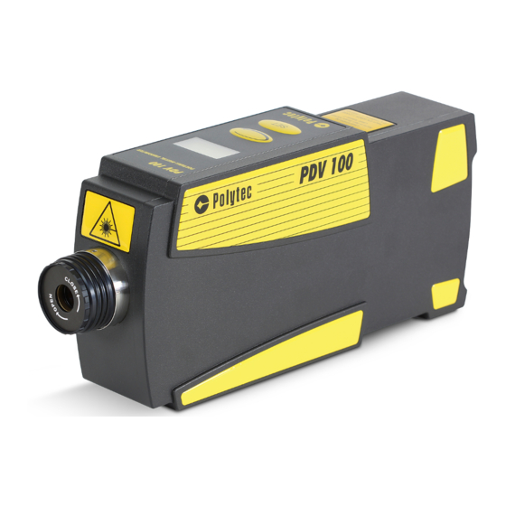
FIGURE Figure 2.1: View of the PDV In the frequency range from 0.05 Hz ... to 22 kHz the handy PDV-100 allows you to realize measurement accuracy which you previously needed a stationary measurement device in a calibration laboratory to achieve. With the three measurement ranges, which cover a velocity range from 0.05 μm / s to... -
Page 12: Measurement Principle
2 Introduction 2.2 Measurement Principle The PDV use the principle of the heterodyne interferometer to acquire the characteristics of mechanical vibrations or transient motion processes (refer B). With this type of interferometer, a high-frequency carrier APPENDIX signal is generated on the photo detector with the aid of a Bragg cell. To make the vibration measurement, the beam of a helium neon laser is pointed at the vibrating object and scattered back from it. -
Page 13: First Steps
3. In the case of wrong delivery, damage or missing parts, inform your local Polytec representative immediately and give them the serial number of the instrument. The identification label can be found on the underside of the instrument and also on the inside cover of this manual. -
Page 14: Operating And Maintenance Requirements
Hard or software components which do not belong to the vibrometer system of other can damage the system. Using them will invalidate the warranty. If you want components to install such components please contact Polytec. Opening the It is not necessary to open the housings when using the equipment as instruments intended and will invalidate the warranty. -
Page 15: Control Elements
3 First Steps 3.3 Control Elements View from The view from above of the PDV with its control elements is shown in above 3.1. FIGURE Figure 3.1: View from above of the PDV Beam shutter Beam shutter to block the laser beam (refer to 5.2) SECTION WARNING! - Page 16 3 First Steps Rear view The rear view of the PDV with its control elements is shown in 3.2. FIGURE A N A L O G O U T D I G I T A L O U T 1 2 V m a x .
-
Page 17: Installation
3 First Steps View from the The view from the bottom of the PDV with its control elements is shown in bottom 3.3. FIGURE Figure 3.3: View from the bottom of the PDV Mounting holes M6 Using these two mounting holes, the PDV can be mounted on cooling metal surfaces. - Page 18 3 First Steps Assembly To mount the PDV on the tripod VIB-A-T01, proceed as follows: onto tripod VIB-A-T01 1. Assemble the tripod as described in the assembly instruction provided by the manufacturer MANFROTTO. 2. Then mount the 3-axes head onto the tripod as described in the assembly instructions provided by the manufacturer MANFROTTO.
-
Page 19: Electrical Connection
3 First Steps 3.4.2 Electrical Connection Mains operation Only use the power supply PDV-AC provided by Polytec. The power supply has a wide range input and can be connected to all mains voltages with nominal values between 100 V to 240 V. - Page 20 PDV reaches its optimal properties after a warm-up period of approx. 20 minutes. If your PDV does not perform as described above, read through the information on fault diagnosis in 6 and if necessary, contact your CHAPTER local Polytec representative.
-
Page 21: Making Measurements
4 Making Measurements 4 Making Measurements 4.1 Start-up To make a measurement with the PDV, proceed as follows: Preparing 1. Make sure, that the beam shutter on the laser vibrometer is closed. 2. Position the PDV roughly so that its laser beam aperture points in the direction of the object under investigation. -
Page 22: Selecting Suitable Settings
4 Making Measurements 4.2 Selecting Suitable Settings 4.2.1 to 4.2.3 you will find information on how to configure SECTION SECTION the right controller settings for velocity measurements as well as to set the high and low pass filters. 4.2.1 Setting the Velocity Measurement Range The PDV offers three velocity measurement ranges, whose full scale values are shown in mm / s (20 mm / s, 100 mm / s, and 500 mm / s) on the display in line Velo. -
Page 23: Setting The High Pass Filter
4 Making Measurements 4.2.3 Setting the High Pass Filter To suppress low-frequency background vibrations, the PDV has got a switchable high pass filter of a 3rd order Butterworth with a cutoff frequency of 100 Hz (− 3 dB). The high pass filter is switched on (Y) and off (N) on the display at HP. -
Page 24: Setting The Optimal Stand-Off Distance
4 Making Measurements 4.3 Setting the Optimal Stand-off Distance 4.3.1 Coherency between Stand-off Distance and Visibility Maximum The light source of the PDV is a helium neon laser. This is a mulit-mode laser in which, depending on the laser cavity length, one or a maximum of two modes can exist. -
Page 25: Stand-Off Distances
4 Making Measurements 4.3.2 Stand-off Distances The stand-off distance is measured from the front edge of the retaining ring for the front lens (refer to 7.2.5). The optimal stand-off distances can SECTION be ascertained as follows: Equation 4.1 0; 1; 2; ... 138 mm i.e. - Page 26 4 Making Measurements...
-
Page 27: Operating The Pdv
5 Operating the PDV 5 Operating the PDV 5.1 Switching On and Off Power Supply You switch the PDV on by connecting the power supply to an earthed socket. The display on top of the PDV lights up and indicates that the PDV is ready to operate. -
Page 28: Using The Signal Level Display
5 Operating the PDV 5.4 Using the Signal Level Display The signal level display helps you to optimize the focus of the laser beam. The signal level is shown as a bar on the display of the PDV (refer to 5.6). -
Page 29: Organization Of The Menus
5 Operating the PDV As the control processor has a flash memory, the settings are stored when the PDV is switched off and reloaded when the PDV is switched on again. This saves time when making adjustments for repeated measurements. 5.6.2 Organization of the Menus The menu structure is shown in 5.3. - Page 30 5 Operating the PDV Service mode Service mode is there to check and calibrate the PDV. You access service mode by holding the key SET pressed and then press the selecting key In the service mode you can set the following operating modes: Switching the Laser On: You can switch the laser on again in the service mode by pressing the key SET several times until the following display appears:...
-
Page 31: Overrange Indicator
5 Operating the PDV 6. Generate the 2.80 V test signal by then pressing the key SET several times until the following display appears. ServiceMode: Output=Full The 2.80 V test signal with approximate full scale is only emitted while this display is shown. This signal is there to check the calibration of the analog signal voltage output. -
Page 32: Battery Level Indicator
5 Operating the PDV 5.8 Battery Level Indicator The battery level indicator is shown on the right of the PDV display next to the overrange indicator (refer to 5.5). FIGURE 5 0 0 Figure 5.5: Display with battery level indicator If the battery level indicator is lit up continuously, it means that the battery is very low. -
Page 33: Fault Diagnosis
6 Fault Diagnosis 6 Fault Diagnosis Some simple tests are described in the following for you to carry out yourself in the case of malfunction. In the case of more difficult problems with the indi- vidual functions, please contact our service personnel. The tests described here are not meant to lead you to carry out maintenance work yourself but to provide our service personnel with information which is as accurate as pos- sible. -
Page 34: No Measurement Signal
6 Fault Diagnosis Only for battery 6. Is the display showing the following warning ? operation WARNING Batt. empty Laser: -Off- The laser has been switched off because the battery is empty. To avoid completely draining the battery and thus shortening its useful life, set the rocker switch of the battery charger in the direction of the charge level indicator. -
Page 35: Technical Specifications
Limit class B IEC / EN 61000-3-2 and 61000-3-3 Immunity: IEC / EN 61000-4-2 to 61000-4-6 and IEC / EN 61000-4-11 7.2 Laser Vibrometer PDV-100 7.2.1 General Data Power Supply Supply voltage: 11 V DC ... 14.5 V DC Operational current: max. -
Page 36: Metrological Properties
7 Technical Specifications Ambient Conditions Operating temperature: +5°C ... +40°C (41°F... 104°F) Storage temperature: 10°C ... +65°C (14°F... 149°F) Operating altitude: max. 3 048 m (10 000ft) Relative humidity: max. 80%, non-condensing Housing Protection reating: IP 64 (corresponding to DIN EN 60529) Dimensions: refer to 7.2.5... - Page 37 7 Technical Specifications Measurement Range Measurement Scaling factor Maximum range full scale Resolution (analog output) acceleration (peak) mm / s m / s < 0.02 2 760 < 0.02 13 800 < 0.1 69 000 adjustable via the display The resolution is defined as the signal amplitude (rms) at which the signal-to-noise ratio is 0 dB in a 1 Hz spectral bandwidth (RBW), measured on 3M Scotchlite Tape®...
- Page 38 7 Technical Specifications - 1 0 1 k H z 5 k H z 2 2 k H z - 2 0 - 3 0 - 4 0 - 5 0 - 6 0 0 , 1 1 0 0 k H z Figure 7.1: Frequency response of the low pass filter High Pass Filter Filter type:...
-
Page 39: Optics
7 Technical Specifications 7.2.3 Optics Laser Laser type: helium neon Wavelength: 633 nm Cavity length: 138 mm Laser class: Laser output power: typ. 0.6 mW Stand-off distance 0.1 ... ca.30 Aperture diameter (1 / e²) [mm] typ. 6.5 Spot size (typ.) [μm] @ 234 mm @ 1 m... -
Page 40: Dimensions
X = 9 6 m m + n · 1 3 8 m m w i t h n = 0 ; 1 ; 2 ; . . . Figure 7.2: Views of the PDV-100 (Dimensions not specified are given in mm.) -
Page 41: Power Supply Pdv-Ac
7 Technical Specifications 7.3 Power Supply PDV-AC Mains Connection Mains voltage: 100 ... 240 VAC ±10%, 50 / 60 Hz Output voltage: 12 V DC Power consumption: max. 20 W Housing Protection rating: with protective insulation, IP40 (correspond to DIN EN 60529) Cable length:... -
Page 42: Optional Accessories
7 Technical Specifications 7.4 Optional Accessories 7.4.1 Mounting Plate VIB-A-P07 Dimensions 1 1 0 2 2 0 1 9 0 L O C K 1 2 0 A D J U S T 3 4 . 5 0 1 . 3 ° 1 . -
Page 43: Battery Charger Pdv-Ch
Identification number: 8932 Voltage: nom. 14.4 V Capacity: nom. 4.6 Ah Operating time with PDV-100: min. 4 h Charge / discharge cycles: min. 500 (with capacity decline to 60%) Housing Dimensions: 80 mm x 70 mm x 115 mm Weight:... -
Page 44: Carrier Bag Pdv-Bs
7 Technical Specifications 7.4.4 Carrier Bag PDV-BS Housing Dimensions: 370 mm x 160 mm x 150 mm Weight: 5.5 kg (incl. PDV, plug-in power supply, 1 battery and battery charger) 7.4.5 Motor Vehicle Supply Cable PDV-DC Connection Data Connector: 12 V DC on-board plug socket with built-in fuse fuse: 2 A / slow-blow Cable length:... -
Page 45: Motor Vehicle Supply Cable Pdv-Dc
PDV accessories in the pockets and under the straps of the carrier bag. Figure A.1: Carrier bag PDV-BS with battery, battery charger and PDV-100 The electrical installation of the carrier bag makes it possible to use the laser... - Page 46 A Optional Accessories A.1.2 Battery Charger PDV-CH Control The view from above of the battery charger with its control elements is shown elements in A A.2. BBILDUNG 1 2 V L a s e r F a i l T e s t C h a r g e 5 0 % 1 0 0 %...
- Page 47 NOTE! Before you connect the plug-in power supply to the mains voltage, check whether the plug-in power supply is equipped with a socket inset suitable for your country. If not, contact your nearest Polytec representative !
- Page 48 A Optional Accessories Charging Before you take the PDV into operation with a battery, you have to charge the battery battery. To do so, proceed as follows: 1. Make sure that the rocker switch on the top of the battery charger is in the middle position.
- Page 49 To charge a reserve battery, connect it to the battery cable of the battery • charger instead of the first battery. CAUTION! Danger from mishandling ! You only may use original lithium ion batteries from Polytec !
- Page 50 A Optional Accessories A.1.3 Battery Operation To take the PDV with a battery into operation, proceed as follows: 1. Make sure that the rocker switch on the top of the battery charger is in the middle position. 2. Plug the vibrometer cable of the battery into the 12 V socket on the back of the PDV and secure the jack with the knurled nut.
- Page 51 A Optional Accessories A.1.4 Mains Operation You can also operate the PDV using the mains connection with the aid of the plug-in power supply - even if the battery is connected. As soon as you plug the power supply connected to the battery charger into a mains earthedl socket and press the rocker switch in the direction of the Laser L the power supply for the PDV is automaticlly changed over to mains operation.
- Page 52 A Optional Accessories...
-
Page 53: Appendix B: Basics Of The Measurement Procedure
B Basics of the Measurement Procedure Appendix B: Basics of the Measurement Procedure Optical interference can be observed when two coherent light beams are made to coincide. The resulting intensity e.g. on a photo detector varies with the phase difference between the two beams according to the equation Equation B.1 The phase difference is a function of the optical path difference L between the two beams according to... - Page 54 B Basics of the Measurement Procedure Interferometers of this type which are directionally sensitive are described as heterodyne.
-
Page 55: Appendix C: Declaration Of Conformity
C Declaration of Conformity Appendix C: Declaration of Conformity Figure C.1: Declaration of conformity for the PDV-100... - Page 56 C Declaration of Conformity...
-
Page 57: Index
VIB-A-T02 jack at the laser vibrometer assemly DIGITAL OUT signal output, technical laser vibrometer specification dimensions laser vibrometer PDV-100 mountain plate VIB-A-P07 basics, measurement procedure directionally sensitive interferometer, basics battery charger display 12V-connecting plug at the laser vibrometer... - Page 58 PDV-100, technical specifications power supply housing surfaces, cleaning...
- Page 59 PDV-CH measurement range PDV-100, technical specifications select power supply setting Velo technical specifications measurement signal qualification of the user generate analog generate digital...
- Page 60 PDV-100, technical specifications optional accessories table power supply specifications, technical dimensions dimensions stand-off distance PDV-100, technical specifications start-up...
- Page 61 Index warming-up warning labels, labels for the sensor head warning on the display Batt. empty Over Temp. wave length, technical specifications weight PDV-100, technical specifications wide range input, power supply working temperature, optimal...
- Page 62 Index...
- Page 63 Contact Polytec Europe Polytec Worldwide Germany (DE) ASEAN Countries Polytec GmbH Polytec South-East Asia Pte. Ltd. Headquarters Blk 4010, Ang Mo Kio Ave 10 Polytec-Platz 1–7 #06-06 TechPlace I 76337 Waldbronn Singapore 569626 Tel.: +49 7243 604-0 Tel.: +65 64510886...
Need help?
Do you have a question about the PDV-100 and is the answer not in the manual?
Questions and answers