
Related Manuals for Polytec TMS-500 TopMap Pro.Surf


Summary of Contents for Polytec TMS-500 TopMap Pro.Surf
- Page 1 Title Operating Instructions 3D Topography Measurement System TMS-500 TopMap Pro.Sur f Sensor Head TMS-I-500 Controller TMS-E-500 Data Management System TMS-W-500...
- Page 2 Warranty and Service The warranty for this equipment complies with the regulations in our general terms and conditions in their respective valid version. This is conditional on the equipment being used as intended and as described in these operating instructions. The warranty does not apply to damage caused by incorrect usage, external mechanical influences or by not keeping to the operating conditions.
-
Page 3: Table Of Contents
Contents Contents 1 Safety Information 1.1 Information on Using these Operating Instructions ............. 1-1 1.1.1 Warning Notices Used ....................1-1 1.1.2 Notices Used ......................1-2 1.2 Warning Labels and Mandatory Signs Used on the Equipment .......... 1-2 1.3 General Safety Information ....................1-3 1.3.1 Operating the Instrument Safely ................ - Page 4 Contents 3.4 Cabling ..........................3-16 3.4.1 Connecting the Hardware ..................3-16 3.4.2 Connecting the Mains Cables .................3-17 3.5 Functional Test .........................3-19 4 Measuring 4.1 Measuring with the Instrument ....................4-1 4.2 High-Precision Measurements ....................4-2 4.3 Setting up the Object Filter ....................4-3 4.4 Maximum Load Capacity of Tip-Tilt Unit ................4-4 5 Technical Specifications 5.1 Harmonized Standards Applied ...................5-1 5.2 Complete System .......................5-1...
-
Page 5: Safety Information
1 Safety Information 1 Safety Information Information on Using these Operating Instructions These operating instructions are part of the product. Keep them within • easy reach. Read these operating instructions carefully before operating the • instrument. Pay attention to any documentation provided by other manufacturers. -
Page 6: Notices Used
1 Safety Information 1.1.2 Notices Used In addition, the following notice is used in these operating instructions which provides additional information on operating the instrument: INFORMATION Provides useful notes and information to simplify the operation of the device. Warning Labels and Mandatory Signs Used on the Equipment There are several warning labels and mandatory signs affixed to the instruments which are briefly explained in the following: Figure 1.1:... -
Page 7: General Safety Information
Any use other than the one described in these operating instructions is not permitted. Polytec rejects any liability for damages which occur from improper use. The instruments are designed in accordance with good engineering practice to meet state-of-the-art safety requirements, have been tested, and left the factory in a condition in which they are safe to operate. -
Page 8: Ambient Conditions
1 Safety Information 1.3.4 Ambient Conditions ATTENTION! Optics impairment caused by condensation! If the instrument is started up in a warm environment after being stored in a cold environment, this can cause condensation which impairs the optical components. The measurement results can thus be falsified. »... -
Page 9: Installing Other Components
Third party hardware or software components could damage the system or impair the function of the software. » To install components which have not been distributed by Polytec, contact Polytec first. » Do not update installed drivers on your Data Management System and do not install optional updates, especially not via the Windows®... -
Page 10: Lamp Safety
» Do not look directly into the illumination module. » Do not use any operating or calibrating equipment other than specified here. 1.4.2 Applicable Standards and Directives Polytec instruments comply with the standards IEC and EN 62471 (Photobiological Safety of Lamps and Lamp Systems). 1.4.3 Equipment Illumination The instrument is equipped with an L -based illumination module. -
Page 11: Electrical Safety
1 Safety Information Electrical Safety 1.5.1 Important Warning Notices WARNING! Fire risk caused by inaccessible or missing disconnection device! A fire risk exists in case of overheating, e.g. due to a device fault. Furthermore, touching hot housing parts can cause burns. The mains switch disconnects the device from the power supply and is used to switch it off in case of danger. -
Page 12: Applicable Standards And Directives
The instrument is subjected to EU directive 2014/30/EU (EMC directive) and therefore conforms with the limits for emission and immunity specified in the standards this is based on. With the CE mark Polytec confirms that the instrument has been tested successfully. -
Page 13: Introduction
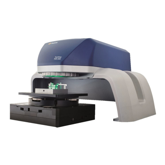
2 Introduction 2 Introduction Area of Application and System Summary The TMS-500 is a 3D topography measurement system for optical, non- contact acquisition of the structure of rough and reflective surfaces. The system components are shown in the following figure. Figure 2.1: System components of the TMS-500... -
Page 14: Operating Principle
2 Introduction Operating Principle The measurement system is based on the principle of the white-light interferometer. In one arm of the interferometer, the object is fixed in position and the interferometer setup is moved relative to the object at a constant speed. -
Page 15: First Steps
1 TFT monitor with monitor cable and mains cable • 3 Mains cables • 1 Hardlock (dongle) • 1 Network cable • 1 USB 3.0 cable (approved by Polytec) • 1 Polytec test object • 1 Motor cable • 1 Control cable •... - Page 16 3. In the case of a wrong delivery, damage or missing parts, immediately inform your local Polytec representative, stating the serial numbers of the instruments. The serial number can be found on the name plate. You will find the name plate on the instruments as well as on the inside cover of these operating instructions.
-
Page 17: Control Elements, Displays, And Connections
3 First Steps Control Elements, Displays, and Connections 3.2.1 Sensor Head Front view The front view of the sensor head with stand and tip-tilt unit is shown in the following figure. Figure 3.1: Front view of the sensor head with stand and tip-tilt unit Beam exit window with filter wheel To adjust various object filters Spacer ring... - Page 18 3 First Steps Back view The back view of the sensor head is shown in the following figure. Figure 3.2: Back view of the sensor head TRANSPORT LOCK transport lock To secure the linear stage to protect the sensor head during transport. Name plate Plate with information on model, serial number, power specifications etc.
- Page 19 3 First Steps Bottom view The bottom view of the sensor head (image section) is shown in the following figure. Figure 3.3: Bottom view of the sensor head (image section) VIDEO USB interface Connection for the USB 3.0 cable to the industrial PC to control the video camera and transmit the video signals.
-
Page 20: Controller
3 First Steps 3.2.2 Controller Front view The front view of the controller is shown in the following figure. Figure 3.4: Front view of the controller POWER status display Status display is lit: The controller is ready for operation. I/O key switch... - Page 21 3 First Steps Back view The back view of the controller is shown in the following figure. Figure 3.5: Back view of the controller ETHERNET network connection Connection for the network cable from the industrial PC MOTOR connection (17-pin circular connection) Connection for the motor cable to the sensor head for the power supply and the signal transmission of the linear stage motor.
-
Page 22: Data Management System
3 First Steps 3.2.3 Data Management System Front view The front view of the industrial PC is shown in the following figure. The front flap is shown as transparent. Figure 3.6: Front view of the industrial PC Cooling fan Status display of the industrial PC Status display is lit: The industrial PC is ready for operation. - Page 23 Use the recovery USB stick to restore the delivery status of the hard disk drive of your Polytec Data Management System. Holder for Polytec Update USB stick Use the Polytec Update USB stick to update your Polytec software. For instructions, see the transparent plastic box.
- Page 24 3 First Steps Back view The back view of the industrial PC is shown in the following figure. Figure 3.8: Back view of the industrial PC Cooling fan Name plate Plate with information on model, serial number, power specifications etc. Warning label Air vents VIDEO USB connection...
-
Page 25: Assembly
3 First Steps 11 Connection for mouse/keyboard (PS/2 interface) Not used 12 COM1 serial interface (9-pin Sub-D plug) Not used 13 DisplayPort connections Not used 14 Mains connection (socket for standard power cord) 15 I/O mains switch Assembly WARNING! Danger of injury and risk of property damage caused by negligent handling of the system! The individual components are heavy and cumbersome. -
Page 26: Mounting The Sensor Head Onto The Stand
Check the devices for external damages such as scratches or the like. In the case of a wrong delivery, damage or missing parts, immediately inform your local Polytec representative, stating the serial numbers of the instruments. INFORMATION Keep the assembly instructions for all components in a safe place. - Page 27 3 First Steps INFORMATION An optical table board (breadboard) with appropriate dimensions and designed for the weight (refer to C 5) can be used as a base plate. HAPTER 1. Place the stand onto the base plate matching up with the drill holes (slots).
-
Page 28: Mounting The Sensor Head Without The Stand
3 First Steps 3.3.2 Mounting the Sensor Head without the Stand CAUTION! Damage to sensor head caused by incorrect handling! To prevent the sensor head from distorting during assembly, you need to fit it accurately and flat on the supporting surface. »... -
Page 29: Mounting Spacer Ring And Tip-Tilt Unit
3 First Steps 3.3.3 Mounting Spacer Ring and Tip-Tilt Unit To assemble the spacer ring with the tip-tilt unit on the base plate, proceed as follows: Spacer ring on 1. Screw the spacer ring onto the base plate using the four screws [C] or [B]. base plate Hand-tighten the screws. -
Page 30: Cabling
ETHERNET ATTENTION! Impaired functionality caused by incorrect cabling! » Solely use the USB 3.0 cable enabled by Polytec to connect the industrial PC and the sensor head. Industrial PC to 4. Plug the USB 3.0 cable into the... -
Page 31: Connecting The Mains Cables
3 First Steps ATTENTION! Damage to the hardware caused by plugging in/unplugging the plug during operation! The hardware can be damaged if the circular connection or the Sub-D connection between the controller and the sensor head is plugged in or unplugged while the instrument is switched on. - Page 32 3 First Steps Figure 3.12: Cabling of the system components 3-18...
-
Page 33: Functional Test
3 First Steps Functional Test The implementation of a first functional test is described in the following. If the instrument does not perform as described, contact your local Polytec representative. For an initial functional test, proceed as follows: 1. Mount the instrument as described in S 3.3. - Page 34 3 First Steps Test 8. Position the Polytec test object within the measurement range [A] on the object support (refer to the following figure). The live video image of the Polytec test object is displayed. Figure 3.13: Measurement range [A] under the beam exit window 9.
-
Page 35: Measuring
4 Measuring 4 Measuring Data acquisition and storage is controlled via the TMS software. A live video image of the object is displayed on the monitor and you can set up the area of interest on this video image. You set all acquisition properties in the TMS software. -
Page 36: High-Precision Measurements
Reference A reference measurement which is balancing the curve in the field of view measurement made by Polytec is included in the TMS software on delivery. After every measurement, this reference measurement is automatically subtracted from your measurement. -
Page 37: Setting Up The Object Filter
4 Measuring Setting up the Object Filter With the object filter you can adjust the intensity of the light scattered back from the object to the intensity of the reference light. The following settings are available: : the object path is hidden •... -
Page 38: Maximum Load Capacity Of Tip-Tilt Unit
4 Measuring Maximum Load Capacity of Tip-Tilt Unit CAUTION! Danger of tilting caused by too heavy objects and lack of stability! When incorrectly placing too heavy objects on the tip-tilt unit, the measurement setup may become unstable and may tilt. »... -
Page 39: Technical Specifications
5 Technical Specifications Technical Specifications Harmonized Standards Applied Lamp safety: IEC/EN 62471 (Photobiological safety of lamps and lamp systems) Electrical safety: IEC/EN 61010-1 (Safety requirements for electrical equipment for measurement, control, and laboratory use) EMC: IEC/EN 61326-1 (EMC requirements on Emission and Immunity - Electrical equipment for measurement, control, and laboratory use) Emission:... - Page 40 5 Technical Specifications Figure 5.1: Views of the sensor head with stand, spacer ring and tip-tilt unit (Unless otherwise specified, all dimensions are in mm.)
-
Page 41: Tms-I-500 Sensor Head
5 Technical Specifications Figure 5.2: Dimensions of the measurement range [A] with stand, spacer ring and tip-tilt unit (Unless otherwise specified, all dimensions are in mm.) TMS-I-500 Sensor Head 5.3.1 General Data Ambient Conditions Operating temperature: +10 … +33 °C (50 … 91.4 °F) Storage temperature: –10 …... - Page 42 5 Technical Specifications Dimensions Figure 5.3: Dimensions of the sensor head from the side with the measurement range [A] (Unless otherwise specified, all dimensions are in mm.) Figure 5.4: Dimensions of the sensor head from the bottom (Unless otherwise specified, all dimensions are in mm.)
-
Page 43: Optics
5 Technical Specifications 5.3.2 Optics Characteristics Vertical measurement range: 70 mm Max. size of area of Version Pixel resolution interest (AOI) [mm x mm] [µm x µm] Large field of 44.9 x 33.8 Lateral 28.2 x 28.2 view (corners clipped) Small field of view 22.8 x 17.2 Lateral 14.3 x 14.3... - Page 44 5 Technical Specifications Metrological Properties Measured under vibration-damped conditions Coherence scanning, Coherence scanning, Phase- analysis: "Smooth Measurement procedure analysis: "Rough Surfaces" shift Surfaces" Specifications for the z performance Measurement noise individual measurement < 0.5 nm < 15 nm < 0.6 nm (Sq-value according to ISO 25178) <...
-
Page 45: Tms-E-500 Controller
5 Technical Specifications Calculating the Measurement Time Equation 5.1 The following values for the measurement time result from a z measurement range of 15 µm and a frame rate of 140 images per second: Sampling increment Measurement time [nm] 87 (nominal) ~1.8 (without averaging) ~0.8 (without averaging) TMS-E-500 Controller... -
Page 46: Tms-W-500 Data Management System
5 Technical Specifications TMS-W-500 Data Management System 5.5.1 General Data Mains Connection Mains voltage: 100 … 240 VAC ±10%, 50/60 Hz Power consumption: max. 525 VA Protection class: 1 (protective grounding) Ambient Conditions Operating temperature: +5 … +40 °C (41 … 104 °F) Storage temperature: –10 …... -
Page 47: A-Spk-0003 Tip-Tilt Unit
5 Technical Specifications A-SPK-0003 Tip-Tilt Unit Weight (tip-tilt unit and spacer ring): 8.5 kg Dimensions spacer ring (w x h):230 mm x 80 mm Max. load capacity: 10 kg (refer to S 4.4) ECTION Dimensions Figure 5.5: Dimensions of the object support on the tip-tilt unit, metric design (Dimensions not specified are given in mm, dimensions in brackets in inch.) - Page 48 5 Technical Specifications Figure 5.6: Dimensions of the object support on the tip-tilt unit, imperial design (Unless otherwise specified, all dimensions are in mm, dimensions in brackets in inch.) 5-10...
-
Page 49: Appendix A: Tms-A-305 Calibration Set
A TMS-A-305 Calibration Set Appendix A: TMS-A-305 Calibration Set A.1 Overview The optional calibration set is used to check the basic metrological properties of the system. The calibration set consists of: Depth setting standard (calibration standard) • Calibration certificate • The depth setting standard is shown in following figure. - Page 50 To define depth setting standards, you require write permissions in the directory C:\Program Files\Polytec. To define the depth setting standard, you proceed as follows: 1. Open the file Standards.xml in a text editor. You will find the file in the following directory: C:\Program Files\Polytec\TMS X.X\Pipeline\AddIns\CalibrationDataEvaluation...
- Page 51 A TMS-A-305 Calibration Set INFORMATION In the Standards.xml file, some values have already been defined by default. 2. Enter the name of the standard and from the calibration certificate, enter the depth, uncertainty and width for every groove and if applicable, delete any values which are not relevant (refer to the following figure).
- Page 52 A TMS-A-305 Calibration Set A.3 Measurements with the Depth Setting Standard Position To position the depth setting standard for measurements, proceed as follows: 1. Position the sensor head and the object support on a vibration-damped table. INFORMATION Do not place moving parts on the vibration-damped table as the measurement results could be affected or falsified.
- Page 53 A TMS-A-305 Calibration Set Measure For measurements on the depth setting standard, proceed as follows: 8. Determine the ambient temperature as precisely as possible to prevent the results of the calibration from being negatively influenced. 9. Define several z-ranges using the measurement sequence table and the calibration depths from the calibration certificate for the depth setting standard (refer to TMS software manual).
- Page 54 A TMS-A-305 Calibration Set A.4 Analyzing the Measurement Result The measurement is analyzed using the CalibrationDataEvaluation add-in. The add-in successively queries the standard used, the ambient temperature as well as the instrument to be calibrated. You can avoid these queries by specifying the information in the file name of the measurement file that is to be analyzed.
- Page 55 A TMS-A-305 Calibration Set INFORMATION To apply the correct value for the ambient temperature, use a comma as the decimal separator. Select Device dialog appears. Figure A.7: Select Device dialog (example) 5. Select the respective device type. 6. Click OK. The TMS software compares the results with the specifications.
- Page 56 A TMS-A-305 Calibration Set Ambient The determined ambient temperature is used to reduce the groove depth to temperature 20 °C, i.e. the groove depth will be calculated that would be the result of a measurement of the depth setting standard at a temperature of 20 °C. The linear thermal expansion coefficient of specified in the calibration certificate is used.
-
Page 57: Appendix B: Eu Declaration Of Conformity
B EU Declaration of Conformity Appendix B: EU Declaration of Conformity Figure B.1: EU declaration of conformity... - Page 58 B EU Declaration of Conformity...
-
Page 59: Index
Index Index figure, devices controller (back view) controller (front view) industrial PC (back view) 3-10 industrial PC (front view) sensor head (back view) air humidity sensor head (bottom view) controller sensor head (front view) industrial PC sensor head ambient conditions, specifications controller guarantee industrial PC... - Page 60 Index name plate VIDEO figure controller figure industrial PC 3-10 figure industrial PC figure sensor head 3-10 figure sensor head inside cover NETWORK, figure industrial PC 3-10 warning label appearance figure controller operating personnel figure industrial PC 3-10 operating system, industrial PC warranty operating temperature wavelength, illumination module (LED)
- Page 61 Contact Polytec Europe Polytec Worldwide Germany (DE) ASEAN Countries Polytec GmbH Polytec South-East Asia Pte. Ltd. Headquarters Blk 4010, Ang Mo Kio Ave 10 Polytec-Platz 1–7 #06-06 TechPlace I 76337 Waldbronn Singapore 569626 Tel.: +49 7243 604-0 Tel.: +65 64510886...
Need help?
Do you have a question about the TMS-500 TopMap Pro.Surf and is the answer not in the manual?
Questions and answers