Table of Contents
Advertisement
Quick Links
Instructions and Parts List
3M-Matic
Accuglide 3
Upper and
Lower
High Speed
Taping Heads
2 Inch
Type 10800
Serial No.
_____________________________________
For reference, record taping head(s) serial number(s) here.
3M Industrial Adhesives and Tapes
3M Center, Building 220-5E-06
St. Paul, MN 55144-1000
™
™
Important Safety
Information
BEFORE INSTALLING
OR OPERATING THIS
EQUIPMENT
Read, understand, and
follow all safety and
operating instructions.
Spare Parts
It is recommended you
immediately order the
spare parts listed in the
"Spare Parts/Service
Information" section.
These parts are expected
to wear through normal
use, and should be kept
on hand to minimize
production delays.
AccuGlide
is a Trademark of
™
3M, St. Paul, MN 55144-1000
Printed in U.S.A.
© 3M 2012 44-0009-2070-0 (E010712-NA)
Advertisement
Table of Contents

Subscribe to Our Youtube Channel
Related Manuals for 3M Matic Accuglide 3


Summary of Contents for 3M Matic Accuglide 3
- Page 1 Serial No. _____________________________________ For reference, record taping head(s) serial number(s) here. 3M Industrial Adhesives and Tapes AccuGlide is a Trademark of ™ 3M, St. Paul, MN 55144-1000 3M Center, Building 220-5E-06 Printed in U.S.A.
-
Page 3: Replacement Parts And Service Information
Included with each machine is an Instructions and Parts List manual. Technical Assistance / Replacement Parts and Additional Manuals: Call the 3M-Matic™ Help line at 1-800 328-1390. Provide the customer support coordinator with the model/machine name, machine type, and serial number that are located on the identification plate (For example: Model 200a - Accuglide 3 - 2 inch - Type 10800 - Serial Number 13282). - Page 4 THIS PAGE IS BLANK...
- Page 5 Order parts by part number, part description, and quantity required. Also, when ordering parts or additional manuals, include model/machine name, machine type, and serial number that are located on the identifi cation plate. 3M Industrial Adhesives and Tapes 3M-Matic , AccuGlide and Scotch ™...
- Page 6 THIS PAGE IS BLANK...
-
Page 7: Table Of Contents
Instruction Manual AccuGlide 3 High Speed 2 Inch ™ Upper and Lower Taping Heads Type 10800 Table of Contents Page Replacement Parts and Service Information .................... i - ii Table of Contents............................Equipment Warranty and Limited Remedy ....................Intended Use ............................Taping Head Contents / How to Use Manual.................... -
Page 8: Equipment Warranty And Limited Remedy
If any part is defective within this warranty period, your exclusive remedy and 3M’s and seller’s sole obligation shall be, at 3M’s option, to repair or replace the part. 3M must receive actual notice of any alleged defect within a reasonable time after it is discovered, but in no event shall 3M have any obligation under this warranty unless it receives such notice within fi... -
Page 9: Intended Use
Scotch ® pressure-sensitive fi lm box sealing tape to other than 3M-Matic™ case sealers. This includes the top and/or bottom center seam of regular slotted replacement of other types of taping, gluing or containers. - Page 10 THIS PAGE IS BLANK...
-
Page 11: Taping Head Contents / How To Use Manual
(ELV), a glossary with a defi nition of symbols, plus a parts list of the 3M-Matic™ Accugllide 3 (2 inch) 3M Industrial Adhesives and Tapes Division 3M Center, Bldg. 220-5E-06 St. Paul, MN 55144-1000 (USA) Edition January 2012/Copyright 3M 2012. All rights reserved The manufacturer reserves the right to change the product at any time without notice. -
Page 12: Important Safeguards
Important Safeguards This safety alert symbol identif es CAUTION important safety messages in this manual. READ AND UNDERSTAND THEM BEFORE INSTALLING OR To reduce the risk associated with muscle • OPERATING THIS EQUIPMENT. strain: Use proper body mechanics when removing or installing taping heads that are Explanation of Signal Word Consequences moderately heavy or may be considered... - Page 13 Important - In the event the following safety labels are damaged or destroyed, they must be replaced to ensure operator safety. See "Replacement Parts Illustrations and Parts Lists" for label part numbers. Upper Taping Head Label 78-8137-3317-3 Lower Taping Head Label 78-8137-3316-5 78-8070-1335-0 Figure 1-1 Replacement Labels/3M Part Numbers 2012 January AccuGlide 3 - 2" - NA...
-
Page 14: Specifications
Guard Width – 107mm [4.2 inches] When upper and lower taping heads are used on “3M-Matic” case sealers, refer to the respective instruction manual specifi cations for box weight and size capacities. Operating Rate: Conveyor speeds up to 0.5 m/s [100 feet per minute]. -
Page 15: Dimensional Drawing
Specifications 405mm [16 in.] Maximum Roll Diameter 443mm [17-7/16 in.] 350mm 33mm [13-3/4 in.] [1-19/64 in.] 278mm 105mm [4-1/8 in.] 60mm [10-15/16 in.] [2-3/8 in.] End View Side View 405mm [16 in.] Maximum Roll Diameter Mounting Holes 76mm [3 in.] 6mm [1/4 in.] Maximum 50mm Tape Leg 18mm [11/16 in.]... -
Page 16: Installation
70mm [2-3/4 inches], the taping heads evident, fi le a damage claim immediately with the must be completely staggered so only one tape transportation company and also notify your 3M seal is being applied at one time. Representative. -
Page 17: Operation
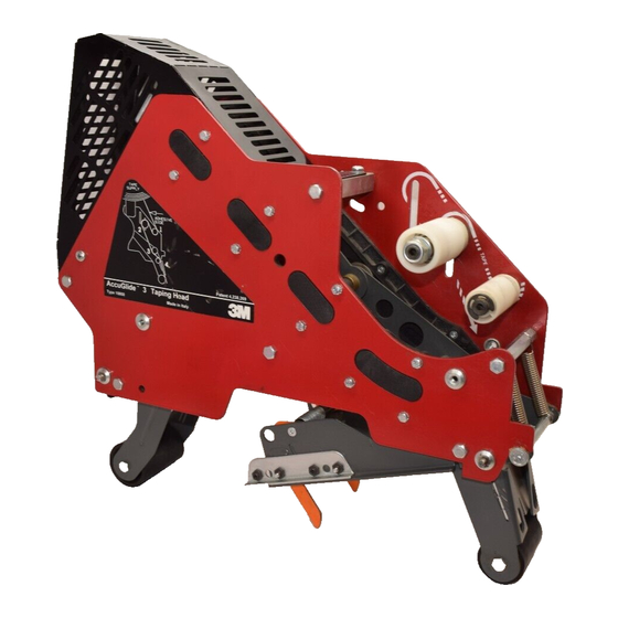
Operation Tape Drum Tape Supply Roll Tape Adhesive Side One-Way Tension Roller Applying Mechanism Tension Wrap Roller Spring Buffing Arm Knurled Roller Cover Wrap Roller Buffing Roller Threading Needle Applying Roller Tape Cut-Off Knife Orange Knife Guard Figure 3-1 Taping Head Components/Threading Diagram - Upper Head (Left Side) View) Orange Knife Guard Tape Cut-Off Knife Applying Roller... -
Page 18: Tape Loading - Upper Taping Head
Operation (continued) WARNING To reduce the risk associated with shear, pinch, and entanglement hazards: • − Turn air and electrical supplies off on associated equipment before performing any adjustments, maintenance, or servicing the machine or taping heads − Never attempt to work on the taping heads or load tape when the box drive system is running To reduce the risk associated with sharp blade hazards: •... - Page 19 Operation (continued) Figure 3-4 Place tape roll on tape drum to dispense tape with adhesive side forward. Seat tape roll fully against back fl ange of drum. Adhere tape lead end to threading needle as shown. Figure 3-4 – Tape Loading/Threading WARNING •...
-
Page 20: Maintenance
Maintenance WARNING To reduce the risk associated with shear, pinch, and entanglement hazards: • − Turn air and electrical supplies off on associated equipment before performing any adjustments, maintenance, or servicing the taping heads − Never attempt to work on the taping head or load tape while the box drive system is running To reduce the risk associated with sharp blade hazards: •... -
Page 21: Cleaning
Maintenance (continued) WARNING To reduce the risk associated with shear, pinch, and entanglement hazards: • − Turn air and electrical supplies off on associated equipment before performing any adjustments, maintenance, or servicing the taping heads − Never attempt to work on the taping head or load tape while the box drive system is running To reduce the risk associated with sharp blade hazards: •... -
Page 22: Adjustments
Adjustments WARNING • To reduce the risk associated with shear, pinch, and entanglement hazards: Turn air and electrical supplies off associated equipment before perform- ing any adjustments, maintenance, or servicing the machine or taping heads. Never attempt to work on the taping head or load tape while the box drive Figure 5-1 –... -
Page 23: Applying Mechanism Spring
Adjustments (continued) WARNING • To reduce the risk associated with shear, pinch, and entanglement hazards: Turn air and electrical supplies off associated equipment before perform- ing any adjustments, maintenance, or servicing the machine or taping heads. Never attempt to work on the taping head or load tape while the box drive system is running Applying Mechanism Spring... -
Page 24: Tape Leg Length
Adjustments (continued) WARNING • To reduce the risk associated with One-Way shear, pinch, and entanglement Tension hazards: Roller Turn air and electrical supplies off associated equipment before perform- ing any adjustments, maintenance, or servicing the machine or taping heads. Never attempt to work on the taping head or load tape while the box drive system is running Tape Leg Length... -
Page 25: Troubleshooting Guide
Troubleshooting Troubleshooting Guide Cause Correction Problem The tape leg on the front of the The tape is threaded incorrectly The tape must go around the wrap roller before going around the case is too long one-way tension roller The tape tension is too low Adjust the one-way tension roller The knurled roller drags Check for adhesive build-up... - Page 26 Troubleshooting (continued) Troubleshooting Guide Cause Correction Problem There is excess tension on the Adjust the one-way tension roller Tape is tabbing on the trailing leg tape drum assembly and/or the and/or the tape drum assembly on the back of the box one-way tension roller assembly Rollers in the tape path do not Clean adhesive deposits from...
-
Page 27: Spare Parts/Service Information
Spare Parts/Service Information Recommended Spare Parts Listed are a set of spare parts that will periodically require replacement due to normal wear. These parts should be ordered to keep the taping heads in production: AccuGlide™ 3 Upper Taping Head - 2 inch Qty. -
Page 28: Replacement Parts Illustrations And Parts List
Not all the parts listed are normally stocked items. Some parts or assemblies shown Important – are available only on a special order basis. Contact 3M/Tape Dispenser Parts to confi rm item availability. 2012 January AccuGlide 3 - 2" - NA... - Page 29 AccuGlide 3 - 2" ™ Tape Head - AccuGlide ™ 3 - 2 inch Figure 10401 Figure 10925 (Haute) Figure 10924 (Bas) Figure 10923 Figure 10922 Figure 10919 (Haute) Figure 10921 Figure 10920 (Bas) 2012 January AccuGlide 3 - 2" - NA...
- Page 30 AccuGlide 3 - 2" ™ Figure 10925 – Upper Head 2012 January AccuGlide 3 - 2" - NA...
- Page 31 AccuGlide 3 - 2" ™ Figure 10925 – 2" Upper Head Ref. No. 3M Part No. Description 10925-1 78-8137-3294-4 Frame – Tape Mount Upper Assembly 10925-2 78-8137-3295-1 Frame – Front Upper Assembly 10925-3 78-8068-4143-9 Guide – #1 10925-4 78-8068-4144-7 Guide – #2...
- Page 32 AccuGlide 3 - 2" ™ 12 11 Figure 10922 – Upper and Lower Heads 2012 January AccuGlide 3 - 2" - NA...
- Page 33 AccuGlide 3 - 2" ™ Figure 10922 – 2" Upper and Lower Heads Ref. No. 3M Part No. Description 10922-1 78-8133-9509-8 Applying Arm #1 10922-2 78-8133-9510-6 Applying Arm #2 10922-3 78-8070-1221-2 Plate – Tape 10922-4 78-8070-1309-5 Shaft Roller 10922-5 78-8070-1367-3 Roller –...
- Page 34 AccuGlide 3 - 2" ™ 12 11 Figure 10919 – Upper Head 2012 January AccuGlide 3 - 2" - NA...
- Page 35 AccuGlide 3 - 2" ™ Figure 10919 – 2" Upper Head Ref. No. 3M Part No. Description 10919-1 78-8137-3300-9 Buffi ng Arm – Sub Assembly 10919-2 78-8137-3301-7 Buffi ng Arm – Sub Assembly 10919-3 78-8052-6575-4 Shaft – Roller 10919-4 78-8137-1398-5 Roller - Buffi...
- Page 36 AccuGlide 3 - 2" ™ Figure 10923 – Upper and Lower Heads Figure 10923 – Upper and Lower Heads 2012 January AccuGlide 3 - 2" - NA 2011 July AccuGlide 3 - 2" - NA...
- Page 37 AccuGlide 3 - 2" ™ Figure 10923 – 2" Upper and Lower Heads Ref. No. 3M Part No. Description 10923-1 78-8137-3302-5 Link – Assembly 10923-3 78-8137-3304-1 Shaft – Pivot, Buffi ng 10923-4 78-8017-9082-1 Bearing – Special 30 mm 10923-5 78-8017-9106-8 Screw –...
- Page 38 AccuGlide 3 - 2" ™ Figure 10921 – Upper and Lower Heads 2012 January AccuGlide 3 - 2" - NA...
- Page 39 AccuGlide 3 - 2" ™ Figure 10921 – 2" Upper and Lower Heads Ref. No. 3M Part No. Description 10921-1 78-8137-3307-4 Frame – Cut-Off Weldment 10921-2 78-8017-9173-8 Blade – 65 mm/2.56 Inch 10921-3 26-1003-8596-7 Screw - Hex Hd M5 x 8 w/ Ext. Tooth Lockwasher...
- Page 40 AccuGlide 3 - 2" ™ Figure 10401 – Upper and Lower Heads 2012 January AccuGlide 3 - 2" - NA...
- Page 41 AccuGlide 3 - 2" ™ Figure 10401 – 2" Latch Upper and Lower Heads Ref. No. 3M Part No. Description 10401-1 78-8070-1395-4 Bracket – Bushing Assembly 10401-2 78-8076-4519-3 Shaft – Tape Drum, 50mm 10401-3 78-8017-9169-6 Nut – M18 x 1...
- Page 42 AccuGlide 3 - 2" ™ 17 19 Figure 10924 – Lower Head 2012 January AccuGlide 3 - 2" - NA...
- Page 43 AccuGlide 3 - 2" ™ Figure 10924 – 2" Lower Head Ref. No. 3M Part No. Description 10924-1 78-8137-3296-9 Frame – Tape Mount Lower Assembly 10924-2 78-8137-3297-7 Frame – Front Lower Assembly 10924-3 78-8068-4144-7 Guide – #2 10924-4 78-8068-4143-9 Guide – #1...
- Page 44 AccuGlide 3 - 2" ™ Figure 10920 – Lower Head 2012 January AccuGlide 3 - 2" - NA...
- Page 45 AccuGlide 3 - 2" ™ Figure 10920– Lower Head Ref. No. 3M Part No. Description 10920-1 78-8137-3300-9 Buffi ng Arm – Sub Assembly 10920-2 78-8137-3301-7 Buffi ng Arm – Sub Assembly 10920-3 78-8052-6575-4 Shaft – Roller 10920-4 78-8137-1398-5 Roller - Buffi ng Assembly...
- Page 46 THIS PAGE IS BLANK...
Need help?
Do you have a question about the Matic Accuglide 3 and is the answer not in the manual?
Questions and answers