Table of Contents
Advertisement
Instructions and Parts List
3M-Matic
700r
Random
Case Sealer
with
AccuGlide
Taping Heads
Serial No.
For reference, record machine serial number here.
3M Packaging Systems Division
3M Center, Building 220-8W-01
St. Paul, MN 55144-1000
TM
Type 39600
II
TM
Important Safety
Information
Read "Important Safeguards",
pages 3-6 and also
operating "Warnings",
page 19 BEFORE
INSTALLING OR
OPERATING THIS
EQUIPMENT.
Spare Parts
It is recommended you
immediately order the spare
parts listed on page 37,
Section I and page 17,
Section II. These parts are
expected to wear through
normal use and should be
kept on hand to minimize
production delays.
"3M-Matic"and "AccuGlide" are Trademarks
of 3M, St. Paul, MN 55144-1000
Litho in U.S.A.
© 3M 1999 44-0009-1907-4 (D29.00)
Advertisement
Table of Contents

Related Manuals for 3M Matic 700r


Summary of Contents for 3M Matic 700r
- Page 1 Serial No. For reference, record machine serial number here. "3M-Matic"and "AccuGlide" are Trademarks 3M Packaging Systems Division of 3M, St. Paul, MN 55144-1000 Litho in U.S.A. 3M Center, Building 220-8W-01 St. Paul, MN 55144-1000 © 3M 1999 44-0009-1907-4 (D29.00)
- Page 2 Minimum billing on parts orders will be $25.00. Replacement part prices available on request. $10.00 restocking charge per invoice on returned parts. Note : Outside the U.S., contact the local 3M subsidiary for parts ordering information. "3M-Matic", "AccuGlide" and “Scotch” are trademarks of 3M Packaging Systems Division 3M, St.
- Page 3 Replacement Parts And Service Information To Our Customers: This is the 3M-Matic™/AccuGlide™/Scotch™ brand equipment you ordered. It has been set up and tested in the factory with "Scotch" brand tapes. If any problems occur when operating this equipment, and you desire a service call, or phone consultation, call, write or Fax the appropriate number listed below.
-
Page 4: Table Of Contents
Instruction Manual 700r, Random Case Sealer, Type 39600 This instruction manual is divided into two sections as follows: Section Includes all information related to installation, operation and parts for the case sealer. Section Includes specific information regarding the AccuGlide™ STD 2 Inch Taping Heads. Table of Contents Page Section... - Page 5 Table of Contents (Continued) Page Maintenance ............................22 - 24 Cleaning ....................... Lubrication ......................Box Drive Belt Replacement ................Circuit Breaker ..................... Knife Replacement, Taping Head ................ Adjustments ............................. 25 - 27 Box Drive Belt Tension ..................25 - 27 Taping Head Adjustments ..................
-
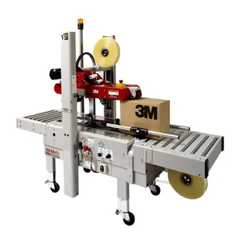
Page 6: Description
Description The 3M-Matic 700r Random Case Sealer with AccuGlide II Taping Heads is designed to apply a “C” clip of Scotch brand pressure-sensitive film box sealing tape to the top and bottom center seam of regular slotted containers. The 700r automatically adjusts to a wide range of box sizes (see "Specifications – Box Weight and Size Capacities", Page 8). -
Page 7: Equipment Warranty And Limited Remedy
3M is notified of the problem no later than five (5) calendar days after the warranty period. If 3M is unable to repair or replace the part within a reasonable time, then 3M at its option, will replace the equipment or refund the purchase price. -
Page 8: Important Safeguards
Important Safeguards The "Warning – Hazardous Voltage" label, shown This safety alert symbol identifies in Figure 1-2, is attached to the cover of the important messages in this manual. electrical control box. The label warns service READ AND UNDERSTAND THEM BEFORE personnel to unplug the power supply before INSTALLING OR OPERATING THIS attempting any service work on the case sealer. - Page 9 Important Safeguards (Continued) A red emergency stop switch is located on the top/ front of the upper drive assembly. The "Stop" label shown in Figure 1-6, is located near the switch and The "Caution – Pinch Point" label, shown in reminds operators and casual personnel of the Figure 1-4, is attached to the center plate at the exit function of this switch.
- Page 10 Important Safeguards (Continued) The "Notice – Raise and Lower Upper Drive Assembly" label, shown in Figure 1-10 is attached to the left column guard at the location of the The "Safety Instructions" and "Air Pressure" mechanical latch. The label provides instructions on labels, shown in Figure 1-8, reminds operator or raising, latching/unlatching and lowering the upper service personnel of the recommended air pressure...
- Page 11 The "Box Centering Switch" label (A), shown in Important Safeguards (Continued) Figure 1-13, is attached to the center plate on the machine bed at the infeed end. The label identifies the box centering switch. The "Centering Guide Force Adjust" label, shown The "Drive Assembly Raising Switch"...
-
Page 12: Specifications
A pressure regulator is included The machine is equipped with two 1/6 HP gearmotors and comes with an 2.4 m [eight foot] standard neoprene covered power cord and a grounded plug. Contact your 3M Representative for power requirements not listed above. - Page 13 (See "Special Set-Up Procedure", page 31.) Special modifications may be available for carton sizes not listed above. Contact your 3M Representative for information. Note: The case sealer can accommodate most boxes within the size range listed above. However, if the box length (in direction of seal) to box height ratio is .5 or less, then several boxes should be test run to...
- Page 14 Specifications (Continued) 10. Machine Dimensions: Minimum 1180 1575 610*** 1640 [Inches] [31] [40 .5] [62] [18] [24] [4.75] [24.5] [64.5] Maximum 2185*** [Inches] [86] [35] * Exit conveyor is optional ** Casters are optional *** When columns are adjusted to upper position, "B" minimum dimension is 570 mm [22.5 inch] and "H"...
-
Page 15: Installation And Set-Up
If damage is evident, file a damage claim immediately with the transportation company and also notify your 3M Representative. The case sealer requires a 5 bar gauge pressure 110 litre/min [70 PSIG], @21°C, 1.01 bar [3.75 SCFM] compressed air supply. As... - Page 16 Installation and Set-Up (Continued) Figure 2-1 – 700r Frame Set-Up 10. Check for free action of both upper and lower 9. Cut and remove cable ties on both upper and taping heads. lower taping heads. (Applying/buffing rollers are held retracted for shipment.) WARNING –...
-
Page 17: Infeed Conveyor Assembly
Installation and Set-Up (Continued) 13. Use appropriate material handling equipment to remove the machine from the pallet and move it into position. Whenever the machine is lifted with a fork truck, insure that the forks span completely across the machine frame and do not contact any wiring or mechanism under the machine frame. -
Page 18: Machine Bed Height
Installation and Set-Up (Continued) MACHINE BED HEIGHT 2. Loosen, but do not remove, two M8 x 1.25 Adjust machine bed height. The case sealer is socket head screws in one leg (use M6 hex equipped with four adjustable legs that are wrench). -
Page 19: Bumper Supports
Installation and Set-Up (Continued) ELECTRICAL CONNECTION AND CONTROLS BUMPER SUPPORTS (Upper Drive Assembly) The electrical control box and "On/Off" switch Raise and lock the upper drive assembly into its are located on the lower left side of the machine raised position. See "Operation – Mechanical frame. -
Page 20: Operation
Operation IMPORTANT – Before operating the case sealer, read the "Important Safeguards", pages 3-6 and "Warnings" on page 19 as well as all of the "Operation" instructions. Refer to Figure 3-1 and 3-2 below to acquaint yourself with the various components and controls of the case sealer. -
Page 21: Machine Switches And Controls
Operation (Continued) Figure 3-2 – Controls, Valves and Switches Always turn the air "Off" when machine is not in Electrical "On/Off" Switch use, when servicing the machine, or when The box drive belts are turned on and off ("Off" connecting or disconnecting air supply line. button is red) with the electrical switch on the side of the machine frame. - Page 22 Operation (Continued) Pressure Regulator regulates main air pressure to the machine to adjust pressure, pull knob up and turn – push down to lock setting. Filter removes dirt and moisture from plant air before it enters the case sealer pneumatic circuits.
- Page 23 Operation (Continued) For boxes which are fully packed with products that support the top flaps, the adjustment of this regulator is not critical since the boxes can support the pressure of the upper frame (drive belts) at a wide range of regulator settings. However, if under-filled or fragile boxes are sealed, this regulator can be used to set the upper frame pressure to a minimum that is still...
-
Page 24: Operating "Warnings
Operation (Continued) WARNINGS 1. Turn electrical and air supply off and disconnect before servicing taping heads or performing any adjustments or maintenance on the machine. 2. Do not leave machine running unattended. 3. Before turning drive belts on, be sure no tools or other objects are on the machine bed. 4. -
Page 25: Theory Of Operation
Operation (Continued) Theory of Operation The air supply powers movement of the centering guides and upper drive assembly to automatically adjust the case sealer to the box size being sealed as follows: 1. A box centering switch in the center of the infeed roller conveyor actuates movement of the centering guides. -
Page 26: Box Sealing
Operation (Continued) WARNING – Keep hands away from drive belts when feeding boxes. 3. Once the box is pushed under the upper taping head, the upper drive assembly raising switch is released causing the upper drive assembly to descend onto the box top, as shown in Figure 3-9, allowing the drive belts to convey the box through the upper and lower taping heads for application of the tape seals. -
Page 27: Maintenance
Maintenance The case sealer has been designed for long, trouble Lubrication free service. The machine will perform best when it receives routine maintenance and cleaning. Most of the machine bearings, including the drive Machine components that fail or wear excessively motor, are permanently lubricated and sealed and should be promptly repaired or replaced to prevent do not require additional lubricant. -
Page 28: Box Drive Belt Replacement
If power cord is not disconnected, severe injury to personnel could result. Box Drive Belt Replacement Note – 3M recommends the replacement of drive belts in pairs, especially if belts are unevenly worn. LOWER DRIVE BELTS Figure 4-2 1. -
Page 29: Circuit Breaker
Maintenance (Continued) WARNING – Turn off electrical power and air supply and disconnect power cord from electrical supply before beginning maintenance. If power cord is not disconnected, severe injury to personnel could result. Circuit Breaker Knife Replacement, Taping Head The case sealer is equipped with a circuit breaker See Section II, "Maintenance –... -
Page 30: Adjustments
Adjustments WARNING – Turn off electrical power and air supply and disconnect power cord from electrical supply before beginning adjustments. If power cord is not disconnected, severe injury to personnel could result. Box Drive Belt Tension The four continuously moving drive belts convey boxes through the tape applying mechanism. The box drive belts are powered by electric gear motors. - Page 31 Adjustments (Continued) WARNING – Turn off electrical power and air supply and disconnect power cord from electrical supply before beginning adjustments. If power cord is not disconnected, severe injury to personnel could result. Refer to Figure 5-2 and 5-3 and adjust belt tension as follows: 1.
-
Page 32: Taping Head Adjustments
Adjustments (Continued) WARNING – Turn off electrical power and air supply and disconnect power cord from electrical supply before beginning adjustments. If power cord is not disconnected, severe injury to personnel could result. Figure 5-3 – Box Drive Belt Tension Adjustment, Upper Belts (Infeed End) Taping Head Adjustments –... - Page 33 THIS PAGE IS BLANK...
-
Page 34: Special Set-Up Procedure
Special Set-Up Procedure WARNING – Turn off electrical power and air supply and disconnect power cord from electrical supply before beginning Special Set-Up Procedure. If power cord is not disconnected, severe injury to personnel could result. Changing the Tape Leg Length (From 70 to 50 mm [2-3/4 to 2 inch]) The following changes to the case sealer frame and upper/lower taping heads reduces the tape leg length to 50 mm [2 inch] and also allows the taping of boxes 95 mm [3.75 inch] minimum height. - Page 35 Special Set-Up Procedure (Continued) TAPING HEADS WARNING – Use care when working near knifes as knifes are extremely sharp. If care is not taken, severe injury to personnel could result. With upper drive assembly in raised position: 1. Remove tape from upper taping head. 2.
-
Page 36: Box And Machine Bed Height Range
Special Set-Up Procedure (Continued) WARNING – Turn off electrical power and air supply and disconnect power cord from electrical supply before beginning Special Set-Up Procedure. If power cord is not disconnected, severe injury to personnel could result. Box and Machine Bed Height Range – Refer to Figure 6-4 Moving the outer columns up one set of mounting holes increases the maximum box size handled by the 700r case sealer and decreases the minimum machine bed height. -
Page 37: Box Height Range
Special Set-Up Procedure (Continued) WARNING – Turn off electrical power and air supply and disconnect power cord from electrical supply before beginning Special Set-Up Procedure. If power cord is not disconnected, severe injury to personnel could result. Box Height Range – (Refer to Figure 6-5) The operating range of the upper drive assembly can be adjusted to minimize its movement to the range of box heights being sealed. -
Page 38: Troubleshooting
Troubleshooting The Troubleshooting Guide lists some possible machine problems, causes and corrections. Also see Section II "Troubleshooting", pages 15 and 16 for taping head problems. Troubleshooting Guide Problem Correction Cause Drive belts do not convey boxes Narrow boxes Check machine specifications. Boxes are narrower than recommended, causing slippage and premature belt wear. - Page 39 Troubleshooting (Continued) Troubleshooting Guide Problem Cause Correction Upper drive assembly does not Lower air pressure Disconnect the air supply. Make move up or moves up slowly sure main pressure regulator reads zero. Reconnect air supply and adjust regulator to read 70 PSIG [5 bar].
-
Page 40: Electrical Diagram
Electrical Diagram WARNING – Turn off electrical power and disconnect power cord from electrical supply before beginning service. If power cord is not disconnected, personnel could be exposed to dangerous voltages that could cause severe injury or equipment damage. Figure 7-1 – Electrical Diagram... -
Page 41: Pneumatic Diagram
Pneumatic Diagram WARNING – Turn off and disconnect air supply before beginning service. If air supply is not disconnected, severe injury or equipment damage could result. Figure 8-1 – Pneumatic Diagram... -
Page 42: Replacement Parts And Service Information
Replacement Parts And Service Information Spare Parts The following parts are normal wear items and should be ordered and kept on hand as used. Qty. Ref. No. Part Number Description 5916-43 & 5918-60 78-8070-1531-4 Belt – Drive W/Pin In addition, a tool/spare parts kit supplied with the 700r Random Case Sealer contains the following spare parts: Qty. -
Page 43: Options/Accessories
Options/Accessories For additional information on the options/accessories listed below, contact your 3M Representative. Part Number Option/Accessory 78-8069-3983-7 Caster Kit Attachment 78-8069-3924-1 Conveyor Extension Attachment (exit only) 78-8069-3926-6 Low Tape Sensor Kit 78-8114-0828-1 AccuGlide II STD 2 Inch Upper Taping Head, Type 39600... -
Page 44: Replacement Parts Illustrations And Parts Lists
Refer to the first page of this instruction manual “Replacement Parts and Service Information” for replacement parts ordering information. IMPORTANT – Not all the parts listed are normally stocked items. Some parts or assemblies shown are available only on special order. Contact 3M/Tape Dispenser Parts to confirm item availability. - Page 45 THIS PAGE IS BLANK...
- Page 46 700r Random Case Sealer Frame Assemblies...
- Page 47 700r Random Case Sealer Figure 2807...
- Page 48 Figure 2807 Ref. No. 3M Part No. Description 2807-1 78-8076-4633-2 Tape Roll Bracket Assembly 2807-2 78-8070-1565-2 Tape Drum Bracket Assembly 2807-3 78-8070-1566-0 Bracket – Tape Drum 2807-4 78-8070-1395-4 Bracket – Bushing Assembly 2807-5 78-8070-1568-6 Cap – Bracket 2807-6 78-8076-4519-3 Shaft – Tape Drum...
- Page 49 700r Random Case Sealer Figure 3437...
- Page 50 Figure 3437 Ref. No. 3M Part No. Description 3437-1 78-8091-0320-9 Conveyor Bed Assembly 3437-2 78-8091-0321-7 Bed – Conveyor 3437-3 78-8091-0307-6 Support – Drive 3437-4 26-1003-5842-8 Screw – Hex Hd, M8 x 20 3437-5 78-8017-9318-9 Washer – Plain, 8 mm 3437-6 78-8076-5381-7 Leg Assembly –...
- Page 51 700r Random Case Sealer Figure 3439...
- Page 52 Figure 3439 Ref. No. 3M Part No. Description 3439-1 78-8076-4663-9 Cylinder – Air /32 x 580 + 20 3439-2 78-8094-6457-7 Cap – 1/8 Inch 3439-3 78-8091-0313-4 Elbow – 3199.08.10 3439-4 78-8076-4680-3 Screw – Cushioning, Cyl/32 3439-5 78-8060-8091-3 Valve – R/O-3-PK-3...
- Page 53 700r Random Case Sealer Figure 5670...
- Page 54 Figure 5670 Ref. No. 3M Part No. Description 5670-1 78-8094-6379-3 Support – Box 5670-2 78-8113-6759-4 Box – W/English Language Label 5670-3 78-8094-6381-9 Screw – Soc Hd, Hex Hd, M4 x 15 5670-4 78-8005-5740-3 Washer – Plain, 4 mm 5670-5 26-1003-6914-4 Nut –...
- Page 55 700r Random Case Sealer Figure 5916/1 of 2...
- Page 56 Figure 5916 (Page 1 of 2) Ref. No. 3M Part No. Description 5916-1 78-8100-1150-8 Bottom Drive Assembly – W/O Motor 5916-2 78-8070-1580-1 Frame – Drive 5916-3 78-8070-1514-0 Spacer 5916-4 26-1003-5829-5 Screw – Hex Hd, M6 x 12 5916-7 78-8052-6710-7 Roller – Idler...
- Page 57 700r Random Case Sealer Figure 5916/2 of 2...
- Page 58 Figure 5916 (Page 2 of 2) Ref. No. 3M Part No. Description 5916-40 78-8052-6713-1 Ring – Polyurethane 5916-41 78-8060-8416-2 Nut – Special, M20 x 1 5916-42 78-8070-1525-6 Chain – 3/8 Inch P=54 5916-43 78-8070-1531-4 Belt – Drive With Hook 5916-44 78-8070-1585-0 Cover –...
- Page 59 700r Random Case Sealer Figure 5917...
- Page 60 Figure 5917 Ref. No. 3M Part No. Description 5917-1 78-8076-4539-1 Column – Outer 5917-2 78-8076-4540-9 Pin – Air Cylinder 5917-3 78-8060-8035-0 E-Ring – 7DIN6799 5917-4 78-8054-8821-6 End – Cap 5917-5 26-1003-7964-8 Screw – Soc Hd Hex Soc Dr, M8 x 20...
- Page 61 700r Random Case Sealer Figure 5918/1 of 2...
- Page 62 Figure 5918 (Page 1 of 2) Ref. No. 3M Part No. Description 5918-1 78-8100-1155-7 Upper Drive Assembly – W /O Motor 5918-2 78-8070-1588-4 Frame – Drive, Upper 5918-3 78-8070-1520-7 Guide – Drive Belt 5918-4 26-1005-4757-4 Screw – Flat Hd, M5 x 20...
- Page 63 700r Random Case Sealer Figure 5918/2 of 2...
- Page 64 Figure 5918 (Page 2 of 2) Ref. No. 3M Part No. Description 5918-38 78-8070-1529-8 Support – Shaft 5918-39 78-8070-1530-6 Bearing – 6205-2RS 5918-40 78-8057-5739-6 Key – M5 x 5 x 30 mm 5918-41 78-8076-5105-0 Pulley Assembly – Drive 5918-42 78-8052-6713-1 Ring –...
- Page 65 700r Random Case Sealer Figure 5919...
- Page 66 Figure 5919 Ref. No. 3M Part No. Description 5919-1 78-8091-0660-8 Housing – Wire 5919-2 78-8076-4702-5 Grommet – /28 5919-3 26-1003-7963-0 Screw – Soc Hd, M8 x 16 5919-4 78-8076-4636-5 Strap – Wire 5919-5 78-8010-7163-6 Screw – Hex Hd, M5 x 10...
- Page 67 700r Random Case Sealer Figure 5920...
- Page 68 Figure 5920 Ref. No. 3M Part No. Description 5920-1 78-8100-1156-5 Infeed Conveyor Assembly 5920-2 78-8100-1157-3 Frame – Infeed 5920-3 78-8076-4566-4 Frame 5920-4 78-8076-4518-5 Spacer – Bearing 5920-5 78-8023-2551-0 Bearing – 6005-2RS 5920-6 78-8076-4567-2 Pivot – Infeed 5920-7 78-8076-4568-0 Key – 7 x 8 x 25...
- Page 69 700r Random Case Sealer Figure 5921...
- Page 70 Figure 5921 Ref. No. 3M Part No. Description 5921-1 78-8100-1163-1 Conveyor Assembly – Infeed 5921-2 78-8076-4513-6 Plate – Reinforcement 5921-3 78-8100-1164-9 Plate 5921-4 78-8076-4625-8 Screw – Special, M5 x 16 5921-5 78-8076-4579-7 Roller – /32 x 492 5921-6 78-8100-1166-4 Plate – Roller...
- Page 71 700r Random Case Sealer Safety and Information Labels...
- Page 72 Qty. 78-8070-1317-8 Label – Centering Guide 78-8070-1329-3 Label – Warning, Hazardous Voltage 78-8070-1336-8 Label – Warning, Sharp Knife 78-8070-1339-2 Information – 3M Logo 78-8069-3852-6 Label – Ground Symbol 78-8068-3859-1 Label – Service and Spares 78-8062-4266-1 Label – Product 78-8070-1319-4 Label – Drive Assembly Raising Switch 78-8070-1332-7 Label –...
Need help?
Do you have a question about the Matic 700r and is the answer not in the manual?
Questions and answers