Table of Contents
Advertisement
Quick Links
https://tehnoteka.rs
Uputstvo za upotrebu (EN)
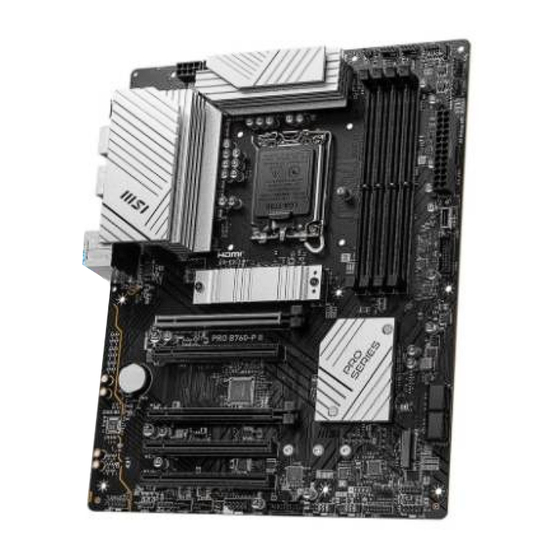
MSI PRO B760-P II matična ploča
Tehnoteka je online destinacija za upoređivanje cena i karakteristika bele tehnike,
potrošačke elektronike i IT uređaja kod trgovinskih lanaca i internet prodavnica u Srbiji.
Naša stranica vam omogućava da istražite najnovije informacije, detaljne karakteristike
i konkurentne cene proizvoda.
Posetite nas i uživajte u ekskluzivnom iskustvu pametne kupovine klikom na link:
https://tehnoteka.rs/p/msi-pro-b760-p-ii-maticna-ploca-akcija-cena/
Advertisement
Table of Contents

Related Manuals for MSI PRO B760-P II


Summary of Contents for MSI PRO B760-P II
- Page 1 Uputstvo za upotrebu (EN) MSI PRO B760-P II matična ploča Tehnoteka je online destinacija za upoređivanje cena i karakteristika bele tehnike, potrošačke elektronike i IT uređaja kod trgovinskih lanaca i internet prodavnica u Srbiji. Naša stranica vam omogućava da istražite najnovije informacije, detaljne karakteristike i konkurentne cene proizvoda.
-
Page 2: Pro Series
PRO Series Motherboard PRO B760-P II User Guide... -
Page 3: Table Of Contents
Contents Quick Start........................4 Specifications ......................16 Special Features ......................20 Package Contents ...................... 21 Back Panel Connectors ..................... 22 LAN Port LED Status Table .................. 23 Audio Jacks Connection ..................23 Overview of Components ................... 25 CPU Socket ......................26 DIMM Slots ...................... - Page 4 Onboard LEDs ......................43 EZ Debug LED ....................... 43 Installing OS, Drivers & MSI Center ................44 MSI Center ......................47 UEFI BIOS ........................48 BIOS Setup ......................49 Resetting BIOS ...................... 50 Updating BIOS ....................... 50 Regulatory Notices ......................i...
-
Page 5: Quick Start
Quick Start Thank you for purchasing a new motherboard from MSI®. This Quick Start section provides demonstration diagrams about how to install your computer. Some of the installations also provide video demonstrations. Please link to the URL to watch it with the web browser on your phone or tablet. -
Page 6: Safety Information
Safety Information ∙ The components included in this package are prone to damage from electrostatic discharge (ESD). Please adhere to the following instructions to ensure successful computer assembly. ∙ Ensure that all components are securely connected. Loose connections may cause the computer to not recognize a component or fail to start. - Page 7 Case stand-off notification To prevent damage to the motherboard, any unnecessary mounting stand-off between the motherboard circuits and the computer case is prohibited. The Case standoff keep out zone signs will be marked on the backside of motherboard (as shown below) to serve as a warning to user.
-
Page 8: Installing A Processor
Installing a Processor ⚽ ∙ https://youtu.be/KMf9oIDsGes... - Page 9 Installing DDR5 memory ⚽ ∙ https://youtu.be/XiNmkDNZcZk DIMMA1 DIMMA2 DIMMA2 DIMMA2 DIMMB1 DIMMB2 DIMMB2...
-
Page 10: Connecting The Front Panel Header
Connecting the Front Panel Header ⚽ ∙ http://youtu.be/DPELIdVNZUI Power LED Power Switch JFP1 Reserved HDD LED Reset Switch JFP1 HDD LED - HDD LED HDD LED + POWER LED - POWER LED POWER LED +... -
Page 11: Installing The Motherboard
Installing the Motherboard ⚽ ∙ https://youtu.be/wWI6Qt51Wnc Torque: 3 kgf·cm* BAT1 *3 kgf·cm = 0.3 N·m = 2.6 lbf·in... -
Page 12: Connecting The Power Connectors
Connecting the Power Connectors ⚽ ∙ http://youtu.be/gkDYyR_83I4 ATX_PWR1 CPU_PWR2 CPU_PWR1... -
Page 13: Installing Sata Drives
Installing SATA Drives ⚽ ∙ http://youtu.be/RZsMpqxythc... -
Page 14: Installing A Graphics Card
Installing a Graphics Card ⚽ ∙ http://youtu.be/mG0GZpr9w_A... -
Page 15: Connecting Peripheral Devices
Connecting Peripheral Devices... - Page 16 Power On...
-
Page 17: Specifications
Specifications ∙ Supports Intel® Core™ 14th/ 13th/ 12th Gen Processors, Intel® Pentium® Gold and Celeron® Processors* ∙ Processor socket LGA1700 * Please go to www.msi.com to get the newest support status as new processors are released. Chipset Intel® B760 Chipset ∙... - Page 18 Continued from previous column ∙ 1x HDMI™ 2.1 port with HDR, supports a maximum resolution of 4K 60Hz*/** ∙ 1x DisplayPort 1.4 port with HBR2, supports a maximum Onboard Graphics resolution of 4K 60Hz*/** * Available only on processors featuring integrated graphics. ** Graphics specifications may vary depending on the CPU installed.
- Page 19 Continued from previous column ∙ 1x USB 3.2 Gen 1 5Gbps Type-C front panel connector (From B760 chipset) ∙ 2x USB 3.2 Gen 1 5Gbps Type-A connectors (From Hub Internal USB GL3523) Connectors • Supports additional 4 USB 3.2 Gen 1 5Gbps ports ∙...
- Page 20 ∙ UEFI AMI BIOS BIOS Features ∙ ACPI 6.4, SMBIOS 3.5 ∙ Multi-language ∙ Drivers ∙ MSI Center ∙ Intel Extreme Tuning Utility Software ∙ MSI APP Player (BlueStacks) ∙ CPU-Z MSI GAMING ∙ Norton 360 ∙ AIDA64 Extreme - MSI Edition...
-
Page 21: Special Features
Special Features MSI Center Features DIY Friendly • Mystic light • PCI-E Steel Armor • Ambient Link • EZ M.2 Clip • Frozr AI Cooling • EZ DEBUG LED • User Scenario Audio • True Color • Audio Boost • Live Update •... -
Page 22: Package Contents
Package Contents Please check the contents of your motherboard package. It should contain: Board • 1x Motherboard Documentation • 1x Quick installation guide • 1x European Union regulatory notice Cables • 1x SATA 6Gb/s cable Accessories • 1x EZ M.2 Clip package (1 set/pack) •... -
Page 23: Back Panel Connectors
Back Panel Connectors Item Description DisplayPort 2.5 Gbps LAN (RJ45) port USB 2.0 Type-A ports (From B760 chipset) Audio jacks HDMI™ port USB 3.2 Gen 1 5Gbps Type-A ports (From B760 chipset) USB 3.2 Gen 2 10Gbps Type-C port (From B760 chipset) Optical S/PDIF Out connector... -
Page 24: Lan Port Led Status Table
LAN Port LED Status Table Link/ Activity LED Speed LED Status Description Status Speed No link 10 Mbps Yellow Linked Green 100/ 1000 Mbps Blinking Data activity Orange 2.5 Gbps Audio Jacks Connection Audio jacks to headphone and microphone diagram Audio jacks to stereo speakers diagram AUDIO INPUT... - Page 25 Audio jacks to 4-channel speakers diagram AUDIO INPUT Rear Front Audio jacks to 5.1-channel speakers diagram AUDIO INPUT Rear Front Center/ Subwoofer Audio jacks to 7.1-channel speakers diagram AUDIO INPUT Rear Front Side Center/ Subwoofer...
-
Page 26: Overview Of Components
Overview of Components SYS_FAN1 SYS_FAN2 ATX_PWR1 JUSB1 SYS_FAN5 JUSB3 M2_1 PCI_E1 M2_2 PCI_E2 BAT1 SATA▼5▲6 PCI_E3 SATA▼7▲8 PCI_E4 JFP2 PCI_E5 JTPM1 JBAT1... -
Page 27: Cpu Socket
∙ Always unplug the power cord from the power outlet before installing or removing the CPU. Please retain the CPU protective cap after installing the processor. MSI will deal ∙ with Return Merchandise Authorization (RMA) requests if only the motherboard comes with the protective cap on the CPU socket. -
Page 28: Dimm Slots
It is recommended to use a more efficient memory cooling system for full DIMMs ∙ installation or overclocking. The stability and compatibility of installed memory module depend on installed CPU ∙ and devices when overclocking. ∙ Please refer to www.msi.com for more information on compatible memory. -
Page 29: Pci_E1~5: Pcie Expansion Slots
PCI_E5: PCIe 3.0 x1 (From B760 chipset) ⚠ Important If you install a large and heavy graphics card, you need to use a tool such as MSI ∙ Graphics Card Bolster to support its weight to prevent deformation of the slot. -
Page 30: M2_1~2: M.2 Slots (Key M)
M2_1~2: M.2 Slots (Key M) ⚠ Important ∙ Intel® RST only supports PCIe M.2 SSD with UEFI ROM. ∙ If your M.2 SSD equips its own heatsink, M2_1 please remove the M.2 rubber cube in the M.2 slot before installing M.2 SSD. Do not re-install the heatsink supplied with your motherboard. - Page 31 3. Install the supplied EZ M.2 Clip according to your SSD length. Skip this step if you install 2280 SSD. 2242 2260 2280 4. Insert your M.2 SSD into the M.2 slot at a 30-degree angle. 5. Rotate the EZ M.2 Clip to fix the M.2 SSD. 2242/ 2260 SSD 30º...
- Page 32 6. Remove the protective films from the thermal pads under the M.2 Shield Frozr heatsink. 7. Put the M.2 Shield Frozr heatsink back in place and secure it. 6 6 7 7 Installing M.2 module into M2_2 slot 1. Please install the supplied M.2 standoff in the M.2 slot according to your SSD length.
-
Page 33: Jaud1: Front Audio Connector
JAUD1: Front Audio Connector This connector allows you to connect audio jacks on the front panel. Signal Name Signal Name MIC L Ground MIC R Head Phone R MIC Detection SENSE_SEND No Pin Head Phone L Head Phone Detection JFP1, JFP2: Front Panel Connectors The JFP1 connector controls the power on, power reset, and the LEDs on your PC case/chassis. -
Page 34: Jci1: Chassis Intrusion Connector
JCI1: Chassis Intrusion Connector This connector allows you to connect the chassis intrusion switch cable. Normal Trigger the chassis (default) intrusion event Using chassis intrusion detector 1. Connect the JCI1 connector to the chassis intrusion switch/ sensor on the chassis. 2. -
Page 35: Cpu_Pwr1, Atx_Pwr1: Power Connectors
CPU_PWR1, ATX_PWR1: Power Connectors These connectors allow you to connect an ATX power supply. CPU_PWR1 Signal Name Signal Name Ground Ground Ground Ground +12V +12V +12V +12V CPU_PWR2 Signal Name Signal Name Ground Ground +12V +12V CPU_PWR1 ATX_PWR1 Signal Name Signal Name CPU_PWR2 +3.3V... -
Page 36: Jcom1: Serial Port Connector
JCOM1: Serial Port Connector This connector allows you to connect the optional serial port with bracket. Signal Name Signal Name SOUT Ground No Pin JUSB1: USB 3.2 Gen 1 Type-C Front Panel Connector This connector allows you to connect USB 3.2 Gen 1 5Gbps Type-C connector on the front panel. -
Page 37: Jusb2~3: Usb 3.2 Gen 1 Connectors
JUSB2~3: USB 3.2 Gen 1 Connectors These connectors allow you to connect USB 3.2 Gen 1 5Gbps ports on the front panel. Signal Name Signal Name Power USB3_RX_DN USB3_RX_DP Ground USB3_TX_C_DN USB3_TX_C_DP Ground USB2.0- USB2.0+ Ground USB2.0+ USB2.0- Ground USB3_TX_C_DP USB3_TX_C_DN Ground USB3_RX_DP... -
Page 38: Jusb4~5: Usb 2.0 Connectors
In order to recharge your iPad, iPhone and iPod through USB ports, please install ∙ MSI Center utility. JTPM1: TPM Module Connector This connector is for TPM (Trusted Platform Module). Please refer to the TPM security platform manual for more details and usages. -
Page 39: Cpu_Fan1, Pump_Fan1, Sys_Fan1~5: Fan Connectors
CPU_FAN1, PUMP_FAN1, SYS_FAN1~5: Fan Connectors Fan connectors can be classified as PWM (Pulse Width Modulation) Mode or DC Mode. PWM Mode fan connectors provide constant 12V output and adjust fan speed with speed control signal. DC Mode fan connectors control fan speed by changing voltage. You can control fans in BIOS>... -
Page 40: Jbat1: Clear Cmos (Reset Bios) Jumper
JBAT1: Clear CMOS (Reset BIOS) Jumper There is CMOS memory onboard that is external powered from a battery located on the motherboard to save system configuration data. If you want to clear the system configuration, set the jumpers to clear the CMOS memory. Keep Data Clear CMOS/ (default) -
Page 41: Jrgb1~2: Rgb Led Connectors
(12V/G/R/B) with the maximum power rating of 3A (12V). Always turn off the power supply and unplug the power cord from the power outlet ∙ before installing or removing the RGB LED strip. Please use MSI’s software to control the extended LED strip. ∙... -
Page 42: Jargb_V2_1~2: A-Rainbow V2 (Argb Gen2) Led Connectors
JARGB_V2_1~2: A-RAINBOW V2 (ARGB Gen2) LED Connectors The JARGB_V2 connectors allow you to connect the ARGB Gen2 and the ARGB-based LED strips. The JARGB_V2 connector supports up to 240 individually addressable RGB LEDs with maximum power rating of 3A (5V). Signal Name Signal Name Data... - Page 43 ∙ the best effects. Always turn off the power supply and unplug the power cord from the power outlet ∙ before installing or removing the addressable RGB LED strip. Please use MSI’s software to control the extended LED strip. ∙...
-
Page 44: Onboard Leds
Onboard LEDs EZ Debug LED These LEDs indicate the debug status of the motherboard. CPU - indicates CPU is not detected or fail. DRAM - indicates DRAM is not detected or fail. VGA - indicates GPU is not detected or fail. BOOT - indicates the booting device is not detected or fail. -
Page 45: Installing Os, Drivers & Msi Center
Installing OS, Drivers & MSI Center Please download and update the latest utilities and drivers at www.msi.com Installing Windows 11 1. Power on the computer. 2. Insert the Windows 11 installation disc/USB into your computer. 3. Press the Restart button on the computer case. - Page 46 2. Select Start > Settings > Windows Update, and then select Check for updates. 3. MSI Driver Utility Installer will pop up automatically. 4. Select the I have read and agree to the MSI Terms of Use check box, and then click Next.
- Page 47 5. Check the Select All checkbox in the lower-left corner and click Install to install MSI Center and drivers. The installation progress will be shown at the bottom. 6. Once the progress has completed, click Finish.
-
Page 48: Msi Center
MSI Center is an application that helps you easily optimize game settings and smoothly use content creation softwares. It also allows you to control and synchronize LED light effects on PCs and other MSI products. With MSI Center, you can customize ideal modes, monitor system performance, and adjust fan speed. -
Page 49: Uefi Bios
UEFI has many new functions and advantages that traditional BIOS cannot achieve, and it will completely replace BIOS in the future. The MSI UEFI BIOS uses UEFI as the default boot mode to take full advantage of the new chipset’s capabilities. -
Page 50: Bios Setup
* When you press F10, a confirmation window appears and it provides the modification information. Select between Yes or No to confirm your choice. BIOS User Guide If you’d like to know more instructions on setting up the BIOS, please refer to https://download.msi.com/archive/mnu_exe/mb/Intel700BIOS.pdf or scan the QR code to access. ⚠ Important... -
Page 51: Resetting Bios
Updating BIOS Updating BIOS with M-FLASH Before updating: Please download the latest BIOS file that matches your motherboard model from MSI website. And then save the BIOS file into the USB flash drive. Updating BIOS: 1. Switch to the target BIOS ROM by Multi-BIOS switch. Please skip this step if your motherboard doesn’t has this switch. - Page 52 ∙ Please close all other application software before updating the BIOS. To update BIOS: 1. Install and launch MSI Center and go to Support page. 2. Select Live Update and click on Advance button. 3. Select the BIOS file and click on Install button.
-
Page 53: Regulatory Notices
∙ This device may not cause harmful interference. ∙ This device must accept any interference received, including interference that may cause undesired operation. MSI Computer Corp. 901 Canada Court, City of Industry, CA 91748, USA (626)913-0828 www.msi.com... -
Page 54: Ce Conformity
∙ ErP Directive 2009/125/EC Compliance with these directives is assessed using applicable European Harmonized Standards. The point of contact for regulatory matters is MSI, MSI-Europe: Eindhoven 5706 5692 ER Son. Compliance Statement of Innovation, Science and Economic Development Canada (ISED) CAN ICES-003(B)/NMB-003(B) クラスB情報技術装置... -
Page 55: Battery Information
Battery Information European Union: Batteries, battery packs, and accumulators should not be disposed of as unsorted household waste. Please use the public collection system to return, recycle, or treat them in compliance with the local regulations. BSMI: 廢電池請回收 For better environmental protection, waste batteries should be collected separately for recycling or special disposal. -
Page 56: Chemical Substances Information
MSI will comply with the product take back requirements at the end of life of MSI-branded products that are sold into the EU. You can return these products to local collection points. - Page 57 à la poubelle. Les fabricants de ces équipements seront obligés de récupérer certains produits en fin de vie. MSI prendra en compte cette exigence relative au retour des produits en fin de vie au sein de la communauté...
- Page 58 MSI oznaku i koji su prodati u EU. Ove proizvode možete vratiti na lokalnim mestima za prikupljanje. POLSKI Aby chronić nasze środowisko naturalne oraz jako firma dbająca o ekologię, MSI przypomina, że...Zgodnie z Dyrektywą Unii Europejskiej (“UE”) dotyczącą odpadów produktów elektrycznych i elektronicznych (Dyrektywa 2002/96/EC), która wchodzi w...
-
Page 59: 日本Jis C 0950材質宣言
№ 1057. Việt Nam RoHS Kể từ ngày 01/12/2012, tất cả các sản phẩm do công ty MSI sản xuất tuân thủ Thông tư số 30/2011/TT-BCT quy định tạm thời về giới hạn hàm lượng cho phép của một số hóa... - Page 60 MS-7E29主板产品中有害物质的名称及含量 有害物质 部件名称 铅 汞 镉 六价铬 多溴联苯 多溴二苯醚 (Pb) (Hg) (Cd) (Cr(VI)) (PBB) (PBDE) 印刷电路板组件* ╳ ○ ○ ○ ○ ○ 纽扣电池 ○ ○ ○ ○ ○ ○ 外部信号连接头 ╳ ○ ○ ○ ○ ○ 其他 (例: 线材等) ╳ ○...
-
Page 61: Copyright And Trademarks Notice
Alternatively, please try the following help resources for further guidance. ∙ Visit the MSI website for technical guide, BIOS updates, driver updates, and other information: http://www.msi.com ∙ Register your product at: http://register.msi.com Revision History ∙... - Page 62 Ovaj dokument je originalno proizveden i objavljen od strane proizvođača, brenda MSI, i preuzet je sa njihove zvanične stranice. S obzirom na ovu činjenicu, Tehnoteka ističe da ne preuzima odgovornost za tačnost, celovitost ili pouzdanost informacija, podataka, mišljenja, saveta ili izjava sadržanih u ovom dokumentu.
Need help?
Do you have a question about the PRO B760-P II and is the answer not in the manual?
Questions and answers
Здравствуйте установил память t-force delta rgb 2x8gb ddr5 6000 мгц в слоты dimma2 и dimmb2 но в биосе показывает что у одной планки частота 6000 а у другой 5600 а в общем работают на частоте 4800, проц i5 12400f
The MSI PRO B760-P II motherboard may show different memory speeds for the T-Force Delta RGB 2x8GB DDR5 6000MHz RAM modules because some memory modules may operate at a lower frequency than the marked value when overclocking. This is due to the memory frequency being dependent on its Serial Presence Detect (SPD). To achieve the marked or higher frequency, you must go to the BIOS and manually set the DRAM Frequency.
This answer is automatically generated