Table of Contents
Advertisement
Quick Links
Advertisement
Table of Contents

Related Manuals for MSI PRO Series


Summary of Contents for MSI PRO Series
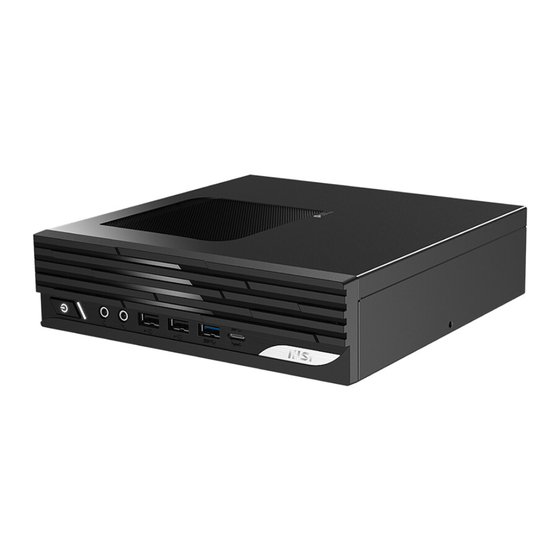
- Page 1 PRO Series Personal Computer PRO DP21 14MQG (MS-B0B2) Service Guide...
-
Page 2: Table Of Contents
Contents Copyright and Trademarks Notice ................. 5 Revision ........................5 How to Use this Service Guide ................5 Safety Instructions ....................6 Power ........................6 Battery ........................6 Environment ......................6 Conditional Warranty Service ................. 7 Upgrade and Service ....................7 Data Sanitization ...................... - Page 3 COM Port Connector Assembly ................24 Coin Battary ......................25 Coin Battary Disassembly ..................25 Coin Battary Assembly ..................26 Mainboard ......................27 Mainboard Disassembly ..................27 Mainboard Assembly .................... 28 Front I/O Board ...................... 29 Front I/O Board Disassembly ................29 Front I/O Board Assembly ..................
- Page 4 Product End-of-Life Instructions ................ 55 Purpose ........................ 55 Information on Component and Material Identification ........55 Product Take-Back Service .................. 56 Using MSI Center ..................57 Login and Register ....................58 Create an Account ....................58 Product Registration .................... 59 Feature Sets ......................
-
Page 5: Copyright And Trademarks Notice
Copyright and Trademarks Notice Copyright © 2023 Micro-Star Int’l Co., Ltd. All rights reserved. The MSI logo used is a registered trademark of Micro-Star Int’l Co., Ltd. Third-party trademarks and names are the properties of their respective owners. No warranty as to accuracy or completeness is expressed or implied. -
Page 6: Safety Instructions
∙ Place the power cord in a way that people are unlikely to step on it. Do not place anything on top of the power cord. ∙ If this product comes with an adapter, use only the MSI provided AC adapter approved for use with this product. -
Page 7: Conditional Warranty Service
MSI offers customers replacement parts, product repair and services for 3 years from the date of sale for all EPEAT-registered products. Damages caused by servicing of products not authorized by MSI or the use of modified or non-MSI authorized parts or components are not covered by MSI Limited Warranty Agreement. -
Page 8: Publicly Available Service Information
Publicly Available Service Information Service Information Section Product Components and Disassembly instructions including Accessories identifying the required tools. Recommended Tools Product Components and Exploded diagram of parts. Accessories List of spare parts including manufacturer- Product Upgradeability and approved spare parts and how to obtain Repairability them. -
Page 9: Disassembly & Assembly
Disassembly & Assembly... -
Page 10: Product Components And Accessories
Product Components and Accessories ⚠ Important MSI provides the below list of components for the system configuration purchased and within 2 years after discontinuation of the product to increase the operational life of that product. Further services can be obtained by contacting... -
Page 11: Product Upgradeability And Repairability
Product Upgradeability and Repairability Hardware features for upgradeable, repairable or replaceable using only commonly available tools and listing of replaceable spare parts by products can be obtained by MSI Online Customer Service contacting hyperlinks For replacement, repair, or upgrade methods, please refer to the in the table below. -
Page 12: Recommended Tools
Recommended Tools The following tools may be needed while performing the disassembly and reassembly procedures. • Cross-head screwdriver • Hex socket screwdriver • Parallel screwdriver (optional) • Tweezers (optional) • Pry tool (optional) • Diagonal pliers (optional) • Heat gun (optional) •... -
Page 13: Screw List
Components EOL Instructions Screw List Please refer to the screw list below while proceeding the disassembly and assembly of the computer. Note: This screw list is for reference only and may vary from models to models. It is highly recommended that users contact the authorized service center for further assistance. -
Page 14: Preparation For Disassembly
Preparation for Disassembly 1. Power off the PC. ❶ 2. Disconnect the power cord from the electrical outlet. ❷ 3. Disconnect the power cord from the PC. ⚠ Important ∙ Disconnect all power sources and place the PC on a steady surface before disassembly/ reassembly. -
Page 15: Stand
Components EOL Instructions Stand Stand Disassembly 1. Place the desktop on a steady, protected surface. ❶ 2. Locate and remove the screw that secure the stand with a cross-head screwdriver. ❷ 3. Remove the stand from the desktop. -
Page 16: Stand Assembly
Stand Assembly 1. Place the desktop on a steady, protected surface. ❶ 2. Place the stand on the desktop with screw hole aligned. ❷ 3. Tighten the screw with a cross-head screwdriver to secure the stand in place. -
Page 17: Top Cover
Components EOL Instructions Top Cover Top Cover Disassembly ❶ 1. Locate and remove the screws that secure the top cover with a cross-head screwdriver. ❷ 2. Remove the top cover from the desktop. -
Page 18: Top Cover Assembly
Top Cover Assembly ❶ 1. Place the top cover on the desktop with screw holes aligned. ❷ 2. Tighten the screws with a cross-head screwdriver to secure the top cover in place. -
Page 19: Hard Disk Drive (Optional)
Components EOL Instructions Hard Disk Drive (Optional) Hard Disk Drive Disassembly ❶ 1. Locate and remove the screws that secure the hard disk drive bracket with a cross-head screwdriver. ❷ ❸ ❹ 2. Disconnect the power cable , signal cable , intrusion cable from the mainboard. -
Page 21: Hard Disk Drive Assembly
Components EOL Instructions Hard Disk Drive Assembly ❶ 1. Place the hard disk drive on the bracket with screw holes aligned, and ❷ then tighten the screws on both sides of the bracket with a cross-head screwdriver to secure the hard disk drive in place. ❸... -
Page 23: Com Port Connector
Components EOL Instructions COM Port Connector COM Port Connector Disassembly ❶ 1. Locate and remove the screws that secure the COM port connector with a hex socket screwdriver. ❷ 2. Remove the COM port connector from the rear I/O shield... -
Page 24: Com Port Connector Assembly
COM Port Connector Assembly ❶ 1. Place the COM port connector on the rear I/O shield with screw holes aligned. ❷ 2. Tighten the screws with a hex socket screwdriver to secure the COM port connector in place. -
Page 25: Coin Battary
Components EOL Instructions Coin Battary ⚠ Important Danger of explosion if battery is incorrectly replaced. Replace only with the same or ∙ equivalent type recommended by the manufacturer. Avoid disposal of a battery into fire or a hot oven, or mechanically crushing or ∙... -
Page 26: Coin Battary Assembly
Coin Battary Assembly ❶ 1. Connect the coin battery cable ❷ 2. Replace the coin battery and secure it with its adhesive tape. -
Page 27: Mainboard
Components EOL Instructions Mainboard Mainboard Disassembly ❶ ❷ 3. Locate and disconnect the front panel cable , COM port cable , antenna ❸ ❹ ❺ ❻ cables , audio cable , USB 2.0 cable , and USB 3.0 cable from the mainboard. -
Page 28: Mainboard Assembly
Mainboard Assembly 1. Place the mainboard on the chassis with screw holes aligned, and then tighten ❶ the screws with a cross-head screwdriver to secure the mainboard in place. ❷ ❸ ❹ 2. Connect the front panel cable , COM port cable , antenna cables , audio ❺... -
Page 29: Front I/O Board
Components EOL Instructions Front I/O Board Front I/O Board Disassembly ❶ ❷ ❸ 1. Locate and disconnect the USB 3.0 cable , USB 2.0 cable , audio cable ❹ and front panel cable from the chassis. ❺ 2. Remove the screws that secure the front I/O board with a cross-head screwdriver, and then remove the front I/O board from the chassis. -
Page 30: Front I/O Board Assembly
Front I/O Board Assembly 1. Place the front I/O board on the chassis with screw holes aligned, and then ❶ tighten the screws with a cross-head screwdriver to secure the front I/O board in place. ❷ ❸ ❹ 2. Connect the USB 3.0 cable , USB 2.0 cable , audio cable , and front panel... -
Page 31: Front Bezel
Components EOL Instructions Front Bezel Front Bezel Disassembly ❶ 1. Locate and disengage the front bezel hooks ❷ 2. Remove the front bezel from the chassis. -
Page 32: Front Bezel Assembly
Front Bezel Assembly ❶ ❷ 1. Place the front bezel on the chassis with its hooks aligned ❸ 2. Engage the front bezel hooks in place... -
Page 33: Rear I/O Shielding
Components EOL Instructions Rear I/O Shielding Rear I/O Shielding Disassembly 1. Locate and disengage the rear I/O shielding, and remove it from the chassis. -
Page 34: Rear I/O Shielding Assembly
Rear I/O Shielding Assembly 1. Place the rear I/O shielding on the chassis, and engage it in place. -
Page 35: Wireless Card
Components EOL Instructions Wireless Card Wireless Card Disassembly ❶ 1. Locate and remove the wireless card clip ❷ 2. Disconnect the antenna cables from the wireless card. ❸ 3. Remove the screw that secures the wireless card with a cross-head screwdriver. -
Page 37: Wireless Card Assembly
Components EOL Instructions Wireless Card Assembly ❶ 1. Locate and tighten the screws that secure the antenna with a cross-head screwdriver. 2. Align the notch on the wireless card with the key on the slot, insert the wireless card into the slot, and push the wireless card downwards. ❷... -
Page 39: Thermal Fan
Components EOL Instructions Thermal Fan Thermal Fan Disassembly ❶ 1. Locate and disconnect the thermal fan cable from the mainboard. ❷ 2. Twist the thermal fan knobs counterclockwise to release the thermal fan, and then pull the knobs up to open the fasteners. 3. -
Page 40: Thermal Fan Assembly
Thermal Fan Assembly 1. Place the thermal fan on the mainboard with knob holes aligned. ❶ 2. Press the thermal fan knobs down to close the fasteners. ❷ 3. Connect the thermal fan cable to the mainboard. -
Page 41: Cpu
Components EOL Instructions ⚠ Important Do not touch the socket contacts or the bottom of the CPU, hold the CPU carefully or ∙ it may cause serious damages. Evenly spread a thin layer of thermal paste on the top of the CPU, this will help in ∙... -
Page 42: Cpu Disassembly
CPU Disassembly 1. Locate and push the load lever down to unclip the CPU socket. Lift the load lever ❶ ❷ up to the fully open position and the load plate will automatically lift up ❸ 2. Remove the CPU straight up from the socket without tilting the CPU. -
Page 43: Cpu Assembly
Components EOL Instructions CPU Assembly 1. Push the load lever down to unclip the CPU socket. Lift the load lever up to the ❶ ❷ fully open position and the load plate will automatically lift up ❸ 2. Align the notches on the CPU with the keys on the socket ❹... -
Page 44: Memory Module
Memory Module Memory Module Disassembly ❶ 1. Locate and open the slot clips on the memory module slot until the memory module pops up. ❷ 2. Remove the memory module from the slot. 3. Repeat the steps if there are more memory modules. -
Page 45: Memory Module Assembly
Components EOL Instructions Memory Module Assembly 1. Align the notch on the memory module with the key on the slot, insert the ❶ memory module into the slot. ❷ 2. Push the memory module downwards until the slot clips click and lock the memory module in place. -
Page 46: Solid State Drive
Solid State Drive Solid State Drive Disassembly ❶ 1. Locate and remove the screw that secures the solid-state drive with a cross- head screwdriver. ❷ 2. Remove the solid-state drive from the M.2 slot. -
Page 47: Solid State Drive Assembly
Components EOL Instructions Solid State Drive Assembly 1. Align the notch on the solid-state drive with the tab on the M.2 slot, insert the ❶ solid-state drive into the M.2 slot, and push the solid-state drive downwards. ❷ 2. Tighten the screw with a cross-head screwdriver to secure the solid-state drive in place. -
Page 48: Tpm Card
TPM Card TPM Card Disassembly ❶ 1. Locate and remove the TPM card... -
Page 49: Tpm Card Assembly
Components EOL Instructions TPM Card Assembly ❶ 1. Insert and push the TPM card downwards. -
Page 50: Powering Up After Maintenance
. 4. Power on the PC. ⚠ Important Use only the MSI provided AC adapter approved for use with this PC. ∙ ∙ If the power cord comes with a 3-pin plug, do not disable the protective earth pin from the plug. -
Page 51: Troubleshooting
Users may refer to the following tips or visit for quick and easy troubleshooting when encountering common problems with the product. It is always suggested that users contact the authorized MSI service center for advanced tech support if needed. My system does not start. - Page 52 System speakers do not work. • Check the master volume setting in the Audio Mixer. • If you are using an application that has its own volume control, check if the volume is muted. • If you have connected an audio cable to the Headphone jack, disconnect it. •...
-
Page 53: Recycling Guidelines
Components EOL Instructions Recycling Guidelines In line with our commitment to environmental sustainability, this product is designed with separable plastic components to enhance plastic recycling quality. We kindly request that you responsibly recycle the recyclable plastic components of this product once it reaches the end of its useful life. -
Page 54: External Power Supply
External Power Supply ❶ 1. Use diagonal pliers to cut the external power supply DC cable ❸ ❷ ❹ of upper and lower cases of the 2. Use heat gun to heat the betweens power adapter, and then use a parallel screwdriver to separate the cases. ❸... -
Page 55: Product End-Of-Life Instructions
EOL Instructions Product End-of-Life Instructions ⚠ Important MSI Environmental Information Information on MSI’s Environmental initiatives, policies, programs and goals can be found at Environmental Sustainability Policy Purpose This information is to provide the guidance to recyclers on the presence of materials and components at the product level, as required by the EU WEEE and amending Directive. -
Page 56: Product Take-Back Service
Product Take-Back Service Waste electrical equipment may contain hazardous substances and thus endanger human health & the environment. Proper disposal is therefore required. MSI provides free recycling of EPEAT-registered products to ensure that the product reaches the end of its useful life and that it is recycled responsibly. -
Page 57: Using Msi Center
Using MSI Center... -
Page 58: Login And Register
MSI product to get full benefits from MSI Center at once. Create an Account 1. Make sure the Internet connection works properly. 2. Activate MSI Center. Click the profile icon at the upper right corner and click [Login]. 3. Select [Join MSI Member]. -
Page 59: Product Registration
Product Registration Once a personal account is created, you may log in and start to register your products. 1. MSI Center will automatically detect your MSI devices. Click [Product Registration] and follow the on-screen instructions to complete the registration. 2. To register more MSI multimedia accessories connected to your system, click [Add New Product] and follow the on-screen instructions to add and register your accessories. -
Page 60: Feature Sets
Feature Sets Users can download, update or uninstall MSI exclusive features in Feature Sets. 1. Click the [Feature Sets] icon at the upper right corner. 2. Install or uninstall any MSI features to meet your personal needs. -
Page 61: Hardware Monitoring
Hardware Monitoring Hardware Monitoring provides real-time status of the CPU, GPU, memory, fans, etc. Click [Free Up Memory] to release system memory that is no longer required. -
Page 62: Features
Features [Features] will vary depending on the features users have installed through [Feature Sets]. -
Page 63: System Diagnosis
∙ To clean up the storage, click [Clean Up Disk], select the drive you want to clean up from the pop-up menu, and follow the on-screen instructions to clean up the storage. ∙ To free up memory, click [Free Up Memory] and MSI Center will instantly release system memory that is no longer required. -
Page 64: Support
Support Support offers various customer support channels to fulfill the needs of every user. Live Update Live Update It is recommended that users click [Scan] under [Live Update] to get the latest MSI or third-party utilities for update. -
Page 65: System Info
Microsoft APP When using this function for the very first time, analyzing the system with Live Update is a must. 1. Click [Scan] under [Live Update]. 2. Click [Microsoft APP] where a list of compatible applications on Microsoft Store are displayed. -
Page 66: Service
Service Forum & Channel • [MSI Forum]: Directing users to MSI Global Forum for discussion with global users. • [How-To Channel]: Directing users to MSI HOW-TO CHANNEL for guides, tips & tricks that help you get more from your MSI products. - Page 67 Troubleshooting • [After-Sales Service]: Providing instructions on repair, warranty and other after- sales services. • [Support Article]: Offering advice on how to troubleshoot your MSI products. If further assistance is needed, click [More] for MSI online service and support.
Need help?
Do you have a question about the PRO Series and is the answer not in the manual?
Questions and answers