
Subscribe to Our Youtube Channel
Related Manuals for Mec 40-AJ


Summary of Contents for Mec 40-AJ
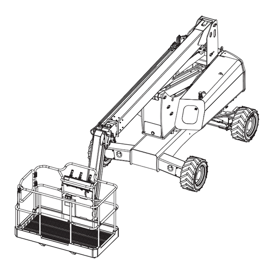
- Page 1 Operator’s Manual 40 - AJ ILLUSTRATION No. ART_6223 Meets requirements of ANSI A92.20-2020 and CSA B354.6-2019. Part # 96822 August 2024 Serial Number Range 15300025 - Up...
-
Page 2: Revision History
August 2024 Revision History Date Reason for Update August 2024 New Release MEC Aerial Work Platforms 1401 S. Madera Avenue, Kerman, CA 93630 USA Toll Free: 1-877-632-5438 Phone: 1-559-842-1500 Fax: 1-559-842-1520 info@MECawp.com www.MECawp.com Page i 40 - AJ - Operator’s Manual - 96822... -
Page 3: Table Of Contents
August 2024 Table of Contents Section 1 - Introduction . Introduction � � � � � � � � � � � � � � � � � � � � � Section 2 - Safety Safety � � � �... -
Page 4: Section 1 - Introduction
Your MEC Aerial Work Platform has been designed, built, and tested to provide safe, dependable service. Only authorized, trained and qualified personnel shall be allowed to operate or service the machine. -
Page 5: Section 2 - Safety
For your safety and the safety of those around you, you must operate your machine as instructed in this manual. MEC designs aerial work platforms to safely and reliably position personnel, along with their necessary tools and materials, at overhead work locations. The owner/user/operator of the machine should not accept responsibility for the operation of the machine unless properly trained. -
Page 6: Safety Alert Symbols & Fall Protection
Section 2 - Safety August 2024 Safety Alert Symbols & Fall Protection MEC manuals and decals use symbols, colors and signal words to help you recognize important safety, operation and maintenance information. ART_6091 RED and the word DANGER – Indicates an imminently hazardous DANGER situation which, if not avoided, will result in death or serious injury. -
Page 7: Section 3 - Specifications
Meets applicable requirements of ANSI A92.20-2020 and CSA B354.6-2019. Allowable ambient temperature range: -20°F to 120°F (-29°C to 49°C). Consult with MEC for operation outside of this range. *Working Height adds 6 feet (2 meters) to platform height. **Weight may increase with certain options. -
Page 8: Section 4 - Hazards
Section 4 - Hazards August 2024 Electrocution Hazard Electrocution Hazard ELECTROCUTION HAZARD! THIS MACHINE IS NOT INSULATED! DEATH OR SERIOUS INJURY will result from contact with or inadequate clearance from any electrically charged conductor. ART_6091 You must maintain a CLEARANCE OF AT LEAST 10 FEET (3.05 meters) DANGER between any part of the machine, or its load, and any electrical line or apparatus carrying over 300 Volts up to 50,000 Volts. - Page 9 Section 4 - Hazards August 2024 5000 V Max. volts Higher voltage 20000 V Min. volts 15000 V 10000 V 5000 V Lower voltage Min. volts (b) Avoid simultaneous contact across (a) Affected area areas of high potential difference CLEARANCES FROM LIVE AERIAL CONDUCTORS Spotter required No go zone...
- Page 10 Section 4 - Hazards August 2024 When working in the area of energized conductors the user shall direct and the operator shall comply with the requirements to: 1) Stay at least 10 feet (3.05 meters) away from power lines with any part of their body, conductive object or any part of the MEWP (Mobile Elevating Work Platform).
-
Page 11: Tip-Over Hazards
NEVER alter or disable any machine components. DO NOT USE AS CRANE DO NOT replace any part of the machine with anything except MEC-supplied or MEC-approved parts. NEVER use ladders or scaffolds in the platform or allow them to touch any part of the machine. -
Page 12: Fall And Collision Hazards
Section 4 - Hazards August 2024 Fall and Collision Hazards Fall Hazards DO NOT sit, stand or climb on the platform guard rails. Maintain a firm footing on the platform floor at all times. Keep the platform floor clear of debris. ILLUSTRATION No. -
Page 13: Additional Safety Hazards
Section 4 - Hazards August 2024 Additional Safety Hazards Explosion and Fire Hazards DO NOT operate the machine in hazardous locations or locations where potentially flammable or • explosive gases or particles may be present. Damaged Machine Hazards • Conduct a thorough pre-start inspection of the machine and test all functions before each work shift to check for damage, malfunction and unauthorized modification. -
Page 14: Section 5 - Controls & Components
Section 5 - Controls & Components August 2024 Component Locations Component Locations RISER BOOM ENGINE SIDE MAIN BOOM CONTROL SIDE JIB BOOM PLATFORM CONTROLS ENTRY GATE PLATFORM FUEL TANK HYDRAULIC TANK LOWER CONTROLS MAIN MANIFOLD ENGINE ILLUSTRATION No. ART_6231 Page 11 40 - AJ - Operator’s Manual - 96822... -
Page 15: Platform Controls
Section 5 - Controls & Components August 2024 Platform Controls ILLUSTRATION No. ART_6224 ALWAYS check over, under and around the machine for personnel, ART_6091 WARNING structures and obstructions before activating any control function and continue to watch for hazards while operating the machine. Controls Description Horn Button... - Page 16 Section 5 - Controls & Components August 2024 When the PPSS first senses an object overhead it activates an intermittent audible alarm. Warn Only The frequency of this alarm increases as the object comes closer to the sensors. Pay careful attention to the object the sensors have detected. PPSS Switch If selected, the machine will stop when the warning alarm becomes continuous.
-
Page 17: Base Controls
Section 5 - Controls & Components August 2024 Base Controls ILLUSTRATION No. ART_6225 ALWAYS check over, under and around the machine for personnel, ART_6091 WARNING structures and obstructions before activating any control function and continue to watch for hazards while operating the machine. Controls Description Hour Meter... - Page 18 Section 5 - Controls & Components August 2024 When this red light is illuminated, the starter circuit is temporarily disabled. The Starter Time-out Indicator starter circuit times out if the starter is run continuously for 20 seconds without the engine starting. The starter functions resets after approximately 30 seconds. Press the Emergency Stop switch at any time to stop all machine functions.
-
Page 19: Section 6 - Workplace Inspection
Section 6 - Workplace Inspection August 2024 Workplace Inspection Workplace Inspection DO NOT operate this machine until you have read and understood this manual, have performed the Workplace Inspection, Pre-Start Inspection and Routine Maintenance, and have completed all the test operations detailed in the Operating Instructions section. Inspect the workplace and determine whether the workplace is suitable for safe machine operation. -
Page 20: Section 7 - Operating Instructions & Pre-Operation Function Tests
Section 7 - Operating Instructions & Pre-Operation Function Tests August 2024 Functions Tests Functions Tests DO NOT operate this machine until you have read and understood this manual, have performed the Workplace Inspection, Pre-Start Inspection and Routine Maintenance, and have completed all the test operations detailed in the Operating Instructions section. - Page 21 Section 7 - Operating Instructions & Pre-Operation Function Tests August 2024 Start/Stop Switch Move the Start/Stop switch upward to start the engine. Release the switch when the engine starts. Press the switch down to stop the engine. ART_4722 Glow Plug Switch With the Glow switch held up, press and hold the Start/Stop switch upward until the engine starts.
- Page 22 Section 7 - Operating Instructions & Pre-Operation Function Tests August 2024 Start/Off Switch Move the Start/Off switch upward to start the engine. Release the switch when the engine starts. Press the switch down to stop the engine. ART_4725 Glow Plug Switch With the Glow switch held up, press and hold the Start/Stop switch upward until the engine starts.
-
Page 23: Base Control Operation & Pre-Operation Functions Test
Section 7 - Operating Instructions & Pre-Operation Function Tests August 2024 Base Control Operation & Pre-Operation Functions Test ILLUSTRATION No. ART_6225 ALWAYS check over, under and around the machine for personnel, ART_6091 WARNING structures and obstructions before activating any control function and continue to watch for hazards while operating the machine. - Page 24 Section 7 - Operating Instructions & Pre-Operation Function Tests August 2024 Function Enable Press and hold this switch to enable and operate machine functions from the base controls. Releasing this switch will disable machine functions. • Press down to operate the controls at slow speed. •...
- Page 25 Section 7 - Operating Instructions & Pre-Operation Function Tests August 2024 Platform Level The platform will automatically level as the boom is lifted or lowered. The Platform Level function allows manual level adjustment of the platform. Manual leveling may be used to adjust the platform within 5°...
- Page 26 Section 7 - Operating Instructions & Pre-Operation Function Tests August 2024 Overload Light and Alarm • Light on indicates too much weight on the platform. • An audible alarm will sound and all machine function will stop. • Remove weight from the platform to restore function and continue. ART_3528 40 - AJ - Operator’s Manual - 96822 Page 23...
-
Page 27: Platform Control Operation & Pre-Operation Functions Test
Section 7 - Operating Instructions & Pre-Operation Function Tests August 2024 Platform Control Operation & Pre-Operation Functions Test ILLUSTRATION No. ART_6224 ALWAYS check over, under and around the machine for personnel, ART_6091 WARNING structures and obstructions before activating any control function and continue to watch for hazards while operating the machine. - Page 28 Section 7 - Operating Instructions & Pre-Operation Function Tests August 2024 Selecting Platform Operation Be sure that the upper and lower Emergency Stop switches are reset. • Lower Control Box: Turn Key Switch to the Platform. ART_4724 Personnel Entry Gates Entering the Platform Lift Gate Personnel shall enter and exit the platform only at the...
- Page 29 Section 7 - Operating Instructions & Pre-Operation Function Tests August 2024 Tilt Indicator Light ART_6091 DANGER STOP ALL MOVEMENT if Tilt Alarm sounds. Light On and alarm sounding indicates an unsafe condition. • STOP ALL MOVEMENT. The machine is not level. •...
-
Page 30: Drive Control Lever Operation
Section 7 - Operating Instructions & Pre-Operation Function Tests August 2024 Drive Control Lever Operation Upper Control Box Depending on the orientation of the boom and chassis, Directional Arrows the Drive and Steer functions may move the machine in directions opposite of the motion of the control lever. The color- and shape-coded arrows on the control lever decal correspond to similar arrow decals on the machine chassis (see illustrations). - Page 31 Section 7 - Operating Instructions & Pre-Operation Function Tests August 2024 Drive & Steer Directional Arrows Pay careful attention to the Chassis Drive & Steer arrows for machine direction. Upper Control Box Platform over non-steering wheels Platform over steering wheels Decals When the platform is over the steering wheels, Decals...
- Page 32 Section 7 - Operating Instructions & Pre-Operation Function Tests August 2024 Engine Speed Select Use this switch to set the engine speed when functions are enabled. Setting this switch to low idle speed allows the operator to move the machine slowly and precisely.
- Page 33 Section 7 - Operating Instructions & Pre-Operation Function Tests August 2024 Riser Boom/Platform/Jib Functions Control Handle The Platform/Jib Functions control handle controls the Platform Rotate, Jib Lift/ Lower functions, and Riser Boom Lift/Lower functions. The control handle is fully proportional for Jib and Platform functions. These functions are enabled by pressing the trigger on the front of the control handle.
-
Page 34: Auxiliary Power System & Test
Section 7 - Operating Instructions & Pre-Operation Function Tests August 2024 Auxiliary Power System & Test If primary power fails while the platform is elevated, use the Auxiliary Power System to safely lower the platform. Do not climb down the boom assembly or exit the platform while ART_6091 WARNING elevated. - Page 35 Section 7 - Operating Instructions & Pre-Operation Function Tests August 2024 The Auxiliary Power System is used to lower the platform in case of primary power failure. To lower the platform, activate the Auxiliary Power Switch to run the auxiliary hydraulic pump. This function uses battery power from the auxiliary battery to lower the platform.
-
Page 36: Section 8 - Maintenance
Section 8 - Maintenance August 2024 Maintenance Maintenance DO NOT operate this machine until you have read and understood this manual, have performed the Workplace Inspection, Pre-Start Inspection and Routine Maintenance, and have completed all the test operations detailed in the Operating Instructions section. Tag and remove a damaged, malfunctioning or modified machine from service. - Page 37 Section 8 - Maintenance August 2024 Watch for makeshift “fixes” which can jeopardize safety as well as lead to more costly repair. ART_6091 CAUTION Inspection and maintenance should be performed by qualified personnel familiar with the equipment. Routine Maintenance IMPORTANT: The operator may perform only maintenance items on the Pre-Start Inspection Checklist.
-
Page 38: Supporting Boom Assembly
Section 8 - Maintenance August 2024 Supporting Boom Assembly ART_6091 NEVER perform work under the boom assembly with the platform WARNING elevated without first supporting the boom assembly. ART_6091 CAUTION Be careful to avoid pinching any electrical harnesses or hydraulic lines. DO NOT work beneath the boom assembly with the platform elevated unless the boom assembly is properly supported! Use a sling and overhead hoist rated for 3 tons (2,700 kg) or more. -
Page 39: Pre-Start Inspection Checklist
Section 8 - Maintenance August 2024 Pre-Start Inspection Checklist NEVER perform work under the boom assembly with the platform elevated without first supporting the boom assembly ART_6091 WARNING Refer to page 35 for instructions. The operator must conduct a Pre-Start Inspection of the machine before each work shift. DO NOT use a damaged or malfunctioning machine! Check that the operator’s manual and manual of responsibilities are in the storage container located on the platform. -
Page 40: Frequent Inspection Checklist
Section 8 - Maintenance August 2024 Frequent Inspection Checklist This checklist must be used at 3-month intervals or every 150 hours of ART_6091 machine use, whichever occurs first. Failure to do so could result in WARNING death or serious injury. Frequent Maintenance Inspections should be conducted by qualified service technicians only. -
Page 41: Maintenance Inspection Report
Section 8 - Maintenance August 2024 Maintenance Inspection Report Booms (34J, 45J, 40AJ, 60J, 65J, 85J) Fleet Equipment Number Date Inspector Name Inspector Co. Model Number Address Serial Number Hour Meter Signature Machine Owner & address Maintain all service records in accordance with ANSI A92.24-2019 * If an inspection receives an “N”, remove from service. -
Page 42: Lubrication
Section 8 - Maintenance August 2024 Lubrication Operator may perform routine maintenance only. Lubrication listed as Scheduled Maintenance must be performed by a qualified service technician. CONTROLS MODULE Components removed for clarity HYDRAULIC FLUID SIGHT GAUGE Add Oil Here LEVEL Fill to Here ILLUSTRATION No. -
Page 43: Section 9 - Troubleshooting Troubleshooting
Wires disconnected, broken, or loose? • Error code at Onboard Diagnostic Center? See Troubleshooting section in the service chapter of the Service & Parts Manual or contact • MEC Customer Service. NVR ECU Terminal Block Module Onboard Diagnostic Center ILLUSTRATION No. -
Page 44: Section 10 - Decals
Section 10 - Decals August 2024 Decals Decals CONTROL SIDE, MODULE CLOSED CONTROL SIDE, MODULE OPEN *On the front of turret. *On the front of turret. ENGINE SIDE, MODULE CLOSED ENGINE SIDE, MODULE OPEN Page 41 40 - AJ - Operator’s Manual - 96822... - Page 45 Section 10 - Decals August 2024 BACK VIEW FRONT VIEW 19 20 *On opposite side of chassis also. *INSIDE THE MANUAL CASE 40 - AJ - Operator’s Manual - 96822 Page 42...
- Page 46 Section 10 - Decals August 2024 91975 Qty. - 2 96426 Qty. - 2 93801 Qty. - 2 93807 Qty. - 2 93755 Qty. - 2 93572 Qty. - 2 96393 Qty. - 1 6873 Qty. - 1 90732 Qty. - 1 93805 Qty.
-
Page 47: Serial Plate Location
Section 10 - Decals August 2024 Serial Plate Location The serial plate is attached to the machine at the time of manufacture. Important information about the machine is recorded on the serial plate. The Serial Plate is located on the side of the chassis below the Base Controls. -
Page 48: Section 11 - Transport And Lifting Instructions
MEC machinery. Truck drivers are responsible for loading and securing machines, and should be properly trained and authorized to operate MEC machinery. ART_6091 WARNING Drivers are also responsible for selecting the correct and appropriate trailer according to government regulations and company policy. - Page 49 Section 11 - Transport and Lifting Instructions August 2024 Driving or Winching onto or off of a Transport Vehicle Before loading the machine, orient the turntable so that the platform is over the non-steering wheels. ONLY properly trained and qualified operators shall load and unload this machine.
- Page 50 Section 11 - Transport and Lifting Instructions August 2024 Securing to Truck or Trailer for Transport Turn the key Selector Key Switch to Off and remove the key before transport. • Turn the Battery Disconnect Switch to Off before transport. •...
-
Page 51: Boom Lifting Instructions
Section 11 - Transport and Lifting Instructions August 2024 Boom Lifting Instructions Only qualified riggers should rig and lift this machine. Ensure that the crane capacity, loading surfaces, chains, straps and ART_6091 slings are sufficient to withstand a machine weight of 11,500lbs (5,216kg). DANGER Ensure that the platform is unloaded and that all material and tools have been removed! - Page 52 August 2024 Notes Page 49 40 - AJ - Operator’s Manual - 96822...
- Page 53 August 2024 Notes Page 50 40 - AJ - Operator’s Manual - 96822...
- Page 54 MEC Parts Order Form Phone: 559-842-1523 Fax: 559-400-6723 Email: Parts@mecawp.com Please Fill Out Completely: Date: Ordered By: Account: Your Fax No.: Bill to: Ship to: Purchase Order Number Ship VIA ** All orders MUST have a Purchase Order Number **Fed Ex shipments require Fed Ex account number...
- Page 55 MEC Aerial Platform Sales Corp. and is found upon inspection by MEC Aerial Platform Sales Corp. to be defective in material and/or workmanship. MEC Aerial Platform Sales Corp. shall not be liable for any consequential, incidental or contingent damages whatsoever.
- Page 56 MEC Aerial Work Platforms 1401 S. Madera Avenue, Kerman, CA 93630 USA Toll Free: 1-877-632-5438 Phone: 1-559-842-1500 Fax: 1-559-842-1520 info@MECawp.com www.MECawp.com...
Need help?
Do you have a question about the 40-AJ and is the answer not in the manual?
Questions and answers