
Subscribe to Our Youtube Channel
Related Manuals for Mec Micro26AC


Summary of Contents for Mec Micro26AC
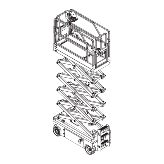
- Page 1 Service & Parts Manual Micro26 ART_5484 This manual applies to AC machines ANSI A92.20-2020 & CSA B354.6-2019. Part # 94225 Serial Number Range 17900100 - Up March 2023...
- Page 2 March 2023 Revision History Date Reason for Update March 2022 New Release MEC Aerial Work Platforms 1401 S. Madera Avenue, Kerman, CA 93630 USA Toll Free: 1-877-632-5438 Phone: 1-559-842-1500 Fax: 1-559-842-1520 info@MECawp.com www.MECawp.com Page i Micro26 - Service & Parts Manual...
-
Page 3: Table Of Contents
Chapter 1 - Service � � � � � � � � � � � � � Service Introduction. Section 1 - MEC Operator Policy MEC Operator Policy � � � � � � � � � � � � � �... - Page 4 March 2023 Section 13 - Battery Charger . 41 Battery Charger � � � � � � � � � � � � � � � � � � � � 41 Section 14 - Fault Codes . 42 Fault Codes �...
- Page 5 March 2023 Section 22 - Decals . . 103 Decals � � � � � � � � � � � � � � � � � � � � � � Page iv Micro26 - Service & Parts Manual...
-
Page 6: Chapter 1 - Service
All parts represented here are manufactured and supplied in accordance with MEC quality standards. We recommend that you use genuine MEC parts to ensure proper operation and reliable performance. To obtain maximum benefits from your MEC Aerial Work Platforms, always follow the proper operating and maintenance procedures. -
Page 7: Section 1 - Mec Operator Policy
Any procedures not found within this manual must be evaluated by the individual to assure oneself that they are “proper and safe.” Your MEC Aerial Work Platform has been designed, built, and tested to provide many years of safe, dependable service. Only trained, authorized personnel should be allowed to operate or service the machine. -
Page 8: Section 2 - Safety Symbols & General Safety Tips
Safety Symbols & General Safety Tips Safety Symbols & General Safety Tips MEC manuals and decals use symbols, colors and signal words to help you recognize important safety, operation and maintenance information. RED and the word DANGER – Indicates an imminently hazardous situation which, if not avoided, will result in death or serious injury. -
Page 9: Section 3 - Specifications
Section 3 - Specifications March 2023 Specifications Specifications Indoor 31 Ft 9.4 m Maximum Working Height* Outdoor 24 Ft 7.3 m Indoor 25 Ft 7.6 m Maximum Platform Height Outdoor 18 Ft 5.5 m Top Guardrail 90.3 in 2.3 m Stowed Height Rails Folded 78.75 in... -
Page 10: Section 4 - Torque Specifications
Section 4 - Torque Specifications March 2023 Bolt Torque Specification - American Standard Bolt Torque Specification - American Standard Fasteners Use the following values to apply torque unless a specific torque value is called out for the part being used. American Standard Cap Screws SAE Grade Cap Screw... -
Page 11: Bolt Torque Specification - Metric Standard
Section 4 - Torque Specifications March 2023 Bolt Torque Specification - Metric Standard Fasteners Use the following values to apply torque unless a specific torque value is called out for the part being used Metric Cap Screws Metric Grade 10.9 10.9 Cap Screw Size Torque... -
Page 12: Hydraulic Components Torque Table
Section 4 - Torque Specifications March 2023 Hydraulic Components Torque Table Note:Always lubricate threads with clean hydraulic fluid prior to installation. Use the following values to torque hydraulic components when a specific value is not available. Always check for torque values in the following places before relying on the Hydraulic Components Torque Table. -
Page 13: Section 5 - Maintenance Lock
Section 5 - Maintenance Lock March 2023 Maintenance Lock Maintenance Lock DEATH OR SERIOUS INJURY HAZARD! NEVER perform work or inspection on the machine with the platform elevated without first blocking the scissor assembly with the Maintenance Lock. DO NOT engage the Maintenance Lock unless the platform in empty of tools and material. - Page 14 Section 5 - Maintenance Lock March 2023 Keep clear of the scissor linkage when lowering. If a Maintenance Lock requires adjustment to stow it correctly, stop the lowering function. Adjust the maintenance lock while stationary, then return to the lowering function. Stowed Maintenance Locks ART_5147...
-
Page 15: Section 6 - Hydraulic, Electrical, And Total Systems
Section 6 - Hydraulic, Electrical, and Total Systems March 2023 Hydraulic, Electrical, and Total Systems Hydraulic, Electrical, and Total Systems Hydraulic System HYDRAULIC FLUID UNDER PRESSURE CAN PENETRATE AND BURN SKIN, DAMAGE EYES, AND MAY CAUSE SERIOUS INJURY, BLINDNESS, AND EVEN DEATH. CORRECT LEAKS IMMEDIATELY. HYDRAULIC FLUID LEAKS UNDER PRESSURE MAY NOT ALWAYS BE VISIBLE. -
Page 16: Section 7 - Components Locations
Section 7 - Components Locations March 2023 Component Locations Component Locations Manuals Case Platform Controls Guard Rails Lanyard Deck Extension Release Anchorage Entry Gate Deck Extension Main Platform Hydraulic Manifold Breather Cap Controls Tray Lift Cylinders Hydraulic Filter Maintenance Hydraulic Lock Reservoir Hydraulic... -
Page 17: Section 8 - Emergency Systems And Procedures
Section 8 - Emergency Systems and Procedures March 2023 Emergency Systems and Procedures Emergency Systems and Procedures IF THE CONTROL SYSTEM FAILS WHILE THE PLATFORM IS ELEVATED, USE THE EMERGENCY LOWERING PROCEDURE TO SAFELY LOWER THE PLATFORM. DO NOT CLIMB DOWN THE ELEVATING ASSEMBLY OR EXIT THE PLATFORM. -
Page 18: Section 9 - Transporting And Lifting Instructions
MEC machinery. Truck drivers are responsible for loading and securing machines, and should be properly trained and authorized to operate MEC machinery. Drivers are also responsible for selecting the correct and appropriate trailer according to government regulations and company policy. Drivers must ensure that the vehicle and chains are strong enough to hold the weight of the machine (see the serial number plate for machine weight). -
Page 19: Driving Or Winching Onto Or Off Of A Transport Vehicle
Section 9 - Transporting and Lifting Instructions March 2023 Driving or Winching onto or off of a Transport Vehicle Always attach the machine to a winch when loading or unloading from a truck or trailer by driving. Read and understand all safety, control, and operating information found on the machine and in this manual before operating the machine. - Page 20 Section 9 - Transporting and Lifting Instructions March 2023 Securing to Truck or Trailer for Transport • Turn the Key Switch to OFF and remove the key before transport. Inspect the entire machine for loose or unsecured items. • • Chock the wheels •...
-
Page 21: Lift And Support The Machine
Section 9 - Transporting and Lifting Instructions March 2023 Lift and Support the Machine DEATH OR SERIOUS PERSONAL INJURY MAY RESULT FROM THE USE OF SUBSTANDARD LIFTING DEVICES AND/OR JACK STANDS. ENSURE THAT ALL LIFTING DEVICES AND JACK STANDS ARE OF ADEQUATE CAPACITY AND IN GOOD WORKING CONDITION BEFORE USE. -
Page 22: Section 10 - Calibration Instructions
Section 10 - Calibration Instructions March 2023 AC Calibrations AC Calibrations ECU Overview ART_5804 Control Description Menu Escape Button Press this button to exit the Menu screen. LED Readout Screen Diagnostic readout and battery charge indicator. Menu Up Button Press this button to go up the Menu items. Menu Down Button Press this button to go down the Menu items. -
Page 23: Ecu Setting And Calibrations
Section 10 - Calibration Instructions March 2023 ECU Setting and Calibrations ECU Setting and Calibrations To enter the ECU setting interface, pull out the emergency stop buttons on lower and upper controls. Press & hold the “Enter” button on lower controls and turn the key switch to the ground controls. - Page 24 Section 10 - Calibration Instructions March 2023 Main Menu Items Value Push to Up 8. Joystick Direction Pull to Up Indoor Mode 9. Enable Indoor/Outdoor Mode Outdoor Mode Dual Cylinder 10. Lowering Cylinder Single Cylinder 11. Test Mode USE WITH CAUTION! 12.
- Page 25 Section 10 - Calibration Instructions March 2023 Calibration The chart below shows what calibration steps that need to be redone after replacing parts! Replaced Part ZAPI ZAPI Angle Pressure Calibration ECU PCU (Pump) (Drive) Sensor Sensor √ Model Selection √ √...
- Page 26 Section 10 - Calibration Instructions March 2023 Full-Load Calibration After entering the Load Calibration sequence, the platform will automatically raise and lower 3- times for each segment. Make sure that the machine is positioned in an area where it can be elevated to full height before initiating the calibration sequence.
- Page 27 Section 10 - Calibration Instructions March 2023 2. Enter the “ECU Settings”. (See page 18) 3. Select “3. Calibration” 4. Select specific height calibration or perform all. See following instructions. OL Descent High Height at which the machine can be lowered when overloaded. Normally, the platform cannot be lowered by controls when overloaded.
-
Page 28: Section 11 - Maintenance
Section 11 - Maintenance March 2023 Daily Maintenance Daily Maintenance The following maintenance should be done every daily or 8 hours of operation whichever comes first. 1) Inspect the Manuals and Decals Maintaining the operator’s manual in good condition is essential to safe machine operation. Manuals are included with each machine and should be stored in the container provided in the platform. - Page 29 Section 11 - Maintenance March 2023 Note: This check is not required for machines with lithium batteries, sealed batteries, or Maintenance - free batteries. Electrocution hazard. Contact with hot or live circuits may result in death or serious injury. Remove all rings, watches and other jewelry. Bodily injury hazard.
- Page 30 Section 11 - Maintenance March 2023 Complete information to perform this procedure is available in the appropriate operator’s manual. Refer to the operator’s manual on your machine. 6) Perform 30 Day Service • Tools maybe be required to perform this procedure. •...
-
Page 31: Quarterly Maintenance
Section 11 - Maintenance March 2023 Quarterly Maintenance The following maintenance should be done every quarter or 250 hours of operation, whichever comes first. 1) Inspect the Batteries • Tools maybe be required to perform this procedure. • New parts maybe be required to perform this procedure. Proper battery condition is essential to good machine performance and operational safety. - Page 32 Section 11 - Maintenance March 2023 2) Inspect the Electrical Wiring • Tools maybe be required to perform this procedure. Maintaining electrical wiring in good condition is essential to safe operation and good machine performance. Failure to find and replace burnt, chafed, corroded or pinched wires could result in unsafe operating conditions and may cause component damage.
- Page 33 Section 11 - Maintenance March 2023 1. Check the tire surface and sidewalls for cuts, cracks, punctures and unusual wear. 2. Check each wheel for damage, bends and cracks. 3. Check each bolt for proper torque. Bolt Torque, Dry 92.2 ft-lbs / 125 Nm Bolt Torque, Lubricated 84.8 ft-lbs / 115 Nm 4) Test the Emergency Stop...
- Page 34 Section 11 - Maintenance March 2023 personnel. An improperly functioning horn will prevent the operator from alerting ground personnel of hazards or unsafe conditions. 1. Turn the key switch to platform control. Pull out the platform and ground red Emergency Stop button to the on position.
- Page 35 Section 11 - Maintenance March 2023 1. Create start and finish lines by marking two lines on the ground 40 ft / 12.2 m apart. 2. Turn the key switch to platform control. Pull out the platform and ground red Emergency Stop button to the on position.
- Page 36 Section 11 - Maintenance March 2023 3. Lower the platform to the stowed position. 4. Press the slow speed select button. 5. Choose a point on the machine; i.e., contact patch of a tire, as a visual reference for use when crossing the start and finish lines.
- Page 37 Section 11 - Maintenance March 2023 Maintaining the module tray latch components in good condition is essential to good performance and service life. Failure to detect worn out latch components may result in module trays opening unexpectedly, creating an unsafe operating condition. 1.
- Page 38 Section 11 - Maintenance March 2023 the platform after the pothole guards are deployed. Adjust or replace the pothole limit switch. 10. Press the drive function select button. Attempt to steer or drive the machine. • Result: The LED readout screen shows code 18, an alarm sounds, and the machine will not steer or drive.
-
Page 39: Semi-Annual Maintenance
Section 11 - Maintenance March 2023 Semi-annual Maintenance The following maintenance should be done every 6 months or 500 hours of operation, whichever comes first. 1) Test the Platform Overload System • Tools maybe be required to perform this procedure. •... - Page 40 Section 11 - Maintenance March 2023 6. Test all machine functions from the platform controls. • Result: All platform control functions should not operate. 7. Turn the key switch to ground control. 8. Test all machine functions from the ground controls •...
-
Page 41: Annual Maintenance
Section 11 - Maintenance March 2023 Annual Maintenance The following maintenance should be done every year or 1,000 hours of operation, whichever 1) Check the Scissor Arm Wear Pads • Tools maybe be required to perform this procedure. • New parts maybe be required to perform this procedure. Maintaining the condition of the scissor arm wear pads is essential to safe machine operation. - Page 42 Section 11 - Maintenance March 2023 Beware of hot oil. Contact with hot oil may cause severe burns. The hydraulic tank return filter is mounted on the bracket between the function manifold and the hydraulic power unit. 1. Clean the area around the oil filter. Remove the filter with an oil filter wrench. 2.
-
Page 43: Biennial Maintenance
Section 11 - Maintenance March 2023 Biennial Maintenance The following maintenance should be done every two years or 2,000 hours of operation, whichever 1) Test or Replace the Hydraulic Oil • Tools maybe be required to perform this procedure. • New parts maybe be required to perform this procedure. - Page 44 Section 11 - Maintenance March 2023 Torque Specifications Hydraulic Tank Drain Plug, Dry 10 in-lbs / 4.5 Nm Hydraulic Tank Drain Plug, Lubricated 30 in-lbs / 3.4 Nm 12. Install the hydraulic tank and install and tighten the hydraulic tank retaining fasteners. Torque to specification.
-
Page 45: Section 12 - Control Components
Section 12 - Control Components March 2023 Control Component Locations Control Component Locations Manuals Case Platform Controls Guard Rails Lanyard Deck Extension Release Anchorage Entry Gate Deck Extension Main Platform Hydraulic Manifold Breather Cap Controls Tray Lift Cylinders Hydraulic Filter Maintenance Hydraulic Lock... -
Page 46: Section 13 - Battery Charger
Section 13 - Battery Charger March 2023 Battery Charger Battery Charger ART_5485 1. The LED display shows 50%, 80% and 100% of battery capacity. When battery capacity is less than the LED marker, the display will blink. The display lights up when capacity has reached the marker level. -
Page 47: Section 14 - Fault Codes
Section 14 - Fault Codes March 2023 Fault Codes Fault Codes The LED readout screen displays fault codes that provide information about the machine operating status and about malfunctions. The fault codes listed in the following charts describe malfunctions and can aid in troubleshooting the machine by pinpointing the area or component affected. - Page 48 Section 14 - Fault Codes March 2023 Code Description Lift Reaction Failure Reason & Solution ECU panel lift buttons failure, ground control operation is Chassis Up or Down Switch prohibited. Disable Chassis Control Solution: Check ECU lift switch. If it faults with platform elevated: The left or right pothole is obstructed.
- Page 49 Section 14 - Fault Codes March 2023 Code Description Lift Reaction Failure Reason & Solution It is reminded that the battery power is lower than the preset Battery Low Voltage Disables All Motion value, and the machine needs to be charged in time to protect the battery from over- discharge and damage.
- Page 50 Section 14 - Fault Codes March 2023 Code Fault name Solution Motor wiring problem. X031 VMN HIGH Check for shorts inside motor. Possible motor-controller problem. Contactor points stuck closed. X037 CONTACTOR CLOSED The large wire of contactor is short-circuited to the positive terminal. Possible controller problem.
- Page 51 Section 14 - Fault Codes March 2023 Code Fault name Solution The motor encoder is broken. X168 SIN/COS D.ERR XX Motor unable to turn. Possible motor controller problem. The motor encoder is broken. X169 ENCODER D.ERR XX Motor unable to turn. Possible motor controller problem.
- Page 52 Section 14 - Fault Codes March 2023 Code Fault name Solution X197 WRONG SLAVE VER. Flash the correct software. X198 M/S PAR CHK MISM Replace Motor controller. X199 PARAM TRANSFER Wait a few seconds and power on again. Check the battery. X200 VDC OFF SHORTED Check motor controller connections.
- Page 53 Replace motor controller. Interference problem, check CAN resistance setting, interference level. X248 NO CAN MSG. For other software setting problems, you need to contact MEC Aerial Work Platforms. X249 CHECK UP NEEDED Change the “CHECK UP DONE” parameter to ON.
-
Page 54: Section 15 - Schematics
Section 15 - Schematics March 2023 Electrical Schematic Electrical Schematic Page 49 Micro26 - Service & Parts Manual... -
Page 55: Electrical Connection Diagram
Section 15 - Schematics March 2023 Electrical Connection Diagram GND-10 BK 8A-2 BN/GN 9B WH/BK B+-A RD 8B BN/RD GND-6 BK Page 50 Micro26 - Service & Parts Manual... -
Page 56: Hydraulic Schematic
Section 15 - Schematics March 2023 Hydraulic Schematic Page 51 Micro26 - Service & Parts Manual... -
Page 57: Chapter 2 - Parts
This Parts sections consists of illustrated parts sections and is designed to provide you, the customer, with illustrations and the list of associated parts needed to properly maintain the MEC self-propelled aerial work platform. When used in conjunction with the Service section in this manual and the Operator’s Manual (provided separately), this manual will assist you in making necessary adjustments... -
Page 58: Section 16 - Chassis
Section 16 - Chassis March 2023 Steer Linkage and Wheels Assembly Steer Linkage and Wheels Assembly ILLUSTRATION No. Micro26 Steer Linkage and Wheels Assembly ART_5864 Page 53 Micro26 - Service & Parts Manual... - Page 59 Section 16 - Chassis March 2023 Item Part Number Description Qty. 43554 Cover 41794 Screw 46232 Steer Yoke Weldment 43556 Bearing 43557 Washer 46233 Drive Motor Assembly 46234 Motor 46235 Reducer 46236 Brake 46237 Wheel 46238 Wheel Bolt 43563 Cotter Pin 41321 41225 Bearing...
-
Page 60: Pothole Protection Assembly
Section 16 - Chassis March 2023 Pothole Protection Assembly ILLUSTRATION No. Micro26 Pothole Protection Assembly ART_5865 Page 55 Micro26 - Service & Parts Manual... - Page 61 Section 16 - Chassis March 2023 Item Part Number Description Qty. 43567 Pothole Guard Weldment 41049 Roller 50050 Nut NNYL M12 × 1.75 43568 Bearing 41604 44889 Seal 43569 Pothole Hole Pusher Assembly 41222 Bearing 41210 Bearing 41807 Lock Clasp 47093 Linkage Weldment 50005...
-
Page 62: Battery Pack Module
Section 16 - Chassis March 2023 Battery Pack Module ILLUSTRATION No. Micro26 Battery Pack Module ART_5866 Page 57 Micro26 - Service & Parts Manual... - Page 63 Section 16 - Chassis March 2023 Item Part Number Description Qty. 46243 Battery Tray Weldment 46244 Battery 50048 Nut NNYL M08 × 1.25 41813 Hinge Pin 41037 Bearing 41814 Washer 43574 Circlips 41120 Bumper 53265 Screw THMS M05-0.80 × 10 41408 Threaded Rod 42896...
-
Page 64: Power Unit Module
Section 16 - Chassis March 2023 Power Unit Module 15 17 16 15 ILLUSTRATION No. Micro26 Power Unit Module ART_5867 Page 59 Micro26 - Service & Parts Manual... - Page 65 Section 16 - Chassis March 2023 Item Part Number Description Qty. Ground Control And Cover Assembly (Refer To Page 63) Hydraulic Tank Assembly (Refer To Page 61) 50313 Nut NNYL M08-1.25 Flange 46249 Hydraulic Tray Weldment 41068 Handle Hole Ring 53231 Screw PHMS M06-1.00 ×...
-
Page 66: Hydraulic Tank Assembly
Section 16 - Chassis March 2023 Hydraulic Tank Assembly ILLUSTRATION No. Micro26 Hydraulic Tank Assembly ART_5868 Page 61 Micro26 - Service & Parts Manual... - Page 67 Section 16 - Chassis March 2023 Item Part Number Description Qty. 41413 41167 Fitting 44002 Washer 41166 Fitting 41082 Breather 41085 Fitting 41412 Tank 46254 Tank 41087 Plug 41824 Filter 44568 Suction Pipe 44567 Washer 41826 Fitting Page 62 Micro26 - Service &...
-
Page 68: Ground Control And Cover Assembly
Section 16 - Chassis March 2023 Ground Control and Cover Assembly ILLUSTRATION No. Micro26 Ground Control and Cover Assembly ART_5869 Page 63 Micro26 - Service & Parts Manual... - Page 69 Section 16 - Chassis March 2023 Item Part Number Description Qty. 46255 Ground Control Bracket 53281 Nut NNYL M05-0.80 Flange 46256 Hinge 53224 Screw THMS M05-0.80 × 12 53279 Screw CSCS M05-0.80 × 12 46257 Cover Ground Control Assembly (Refer To Page 65) 53038 WSHR M05 Standard Flat Washer 53043...
-
Page 70: Ground Control Assembly
Section 16 - Chassis March 2023 Ground Control Assembly ILLUSTRATION No. Micro26 Ground Control Assembly ART_5870 Page 65 Micro26 - Service & Parts Manual... - Page 71 Section 16 - Chassis March 2023 Item Part Number Description Qty. 46258 Shell Components 41568 Alarm 43631 Alarm Nut 44691 Alarm Harness 44692 Main Board 44693 Display 44795 Decal, Ground Control Panel 41418 Key Switch 91574 41157 Emergency Stop Switch 43632 Red Mushroom Head 43633...
-
Page 72: Pump Motor Assembly
Section 16 - Chassis March 2023 Pump Motor Assembly ILLUSTRATION No. Micro26 Pump Motor Assembly ART_5871 Page 67 Micro26 - Service & Parts Manual... - Page 73 Section 16 - Chassis March 2023 Item Part Number Description Qty. 53315 Screw SHCS 3/8-24 × 1 1/4 53054 WSHR M10 Spring Washer 50002 WSHR M10 Standard Flat Washer 43205 Straight Fitting 41426 Pump 46259 Motor 46260 Straight Fitting Page 68 Micro26 - Service &...
-
Page 74: Rear Wheel And Ladder
Section 16 - Chassis March 2023 Rear Wheel and Ladder ILLUSTRATION No. Micro26 Rear Wheel and Ladder ART_5872 Page 69 Micro26 - Service & Parts Manual... - Page 75 Section 16 - Chassis March 2023 Item Part Number Description Qty. 46237 Wheel 46238 Bolt 41328 53282 Screw CSCS M08-1.25 × 20 41025 Bearing Seat 41002 Spacer 43585 Cotter Pin 43586 Spindle 46261 Ladder 50429 Screw HHCS M10-1.50 × 25 Serrated Flange 41003 Ground Strap 53260...
-
Page 76: Charger Assembly
Section 16 - Chassis March 2023 Charger Assembly ILLUSTRATION No. Micro26 Charger Assembly ART_5873 Page 71 Micro26 - Service & Parts Manual... - Page 77 Section 16 - Chassis March 2023 Item Part Number Description Qty. 42903 Charger 46262 Charger Bracket Weldment 53221 Screw CSCS M04-0.70 × 16 41575 Plug 53263 Screw THMS M04-0.70 × 8 43591 Plug Bracket 50568 Nut NNYL M06-1.00 Flange 53264 Screw PHMS M06-1.00 ×...
-
Page 78: Chassis Accessory Installation
Section 16 - Chassis March 2023 Chassis Accessory Installation 14 13 12 ILLUSTRATION No. Chassis Accessory Installation Micro26 ART_5874 Page 73 Micro26 - Service & Parts Manual... - Page 79 Section 16 - Chassis March 2023 Item Part Number Description Qty. 53449 Screw HHCS M05-0.80 × 10 Flange 44895 Cover 53223 Screw THMS M05-0.80 × 16 41309 Beacon Cover 46264 Beacon 41051 Bearing 53067 Screw SHCS M05-0.80 × 40 53038 WSHR M05 Standard Flat Washer 53281 Nut NNYL M05-0.80 Flange...
-
Page 80: Section 17 - Scissor
Section 17 - Scissor March 2023 Scissor Assembly Scissor Assembly Right Left ILLUSTRATION No. Micro26 Scissor Assembly ART_5875 Page 75 Micro26 - Service & Parts Manual... - Page 81 Section 17 - Scissor March 2023 Item Part Number Description Qty. 53267 Screw HHCS M10-1.50 × 110 Flange 43595 Cable Bridge 44533 Clamp 50022 Screw HHCS M10-1.50 × 70 50049 Nut NNYL M10 × 1.50 43596 Cable Bridge 43597 Circlips Upper Lift Cylinder Assembly (Refer To Page 91) 41686 Inner Arm 3...
- Page 82 Section 17 - Scissor March 2023 Inner Arm 5 43609 REF - Reference Page 77 Micro26 - Service & Parts Manual...
- Page 83 Section 17 - Scissor March 2023 THIS PAGE HAS BEEN INTENTIONALLY LEFT BLANK. Page 78 Micro26 - Service & Parts Manual...
-
Page 84: Section 18 - Platform
Section 18 - Platform March 2023 Main Platform Assembly Main Platform Assembly ILLUSTRATION No. Micro26 Main Platform Assembly ART_5876 Page 79 Micro26 - Service & Parts Manual... - Page 85 Section 18 - Platform March 2023 Item Part Number Description Qty. 46280 Upper Main Rail, Left 46281 Lower Main Rail, Right 46282 Upper Main Rail, Right 43337 Lock Pin 43301 Rivet 41128 Hinge B 53273 Screw HHCS M06-1.00 × 14 Serrated Flange 41127 Hinge A 43613...
-
Page 86: Platform Extension Assembly
Section 18 - Platform March 2023 Platform Extension Assembly 16 15 14 ILLUSTRATION No. Micro26 Platform Extension Assembly ART_5877 Page 81 Micro26 - Service & Parts Manual... - Page 87 Section 18 - Platform March 2023 Item Part Number Description Qty. 46285 Upper Extension Rail, Left 53281 Nut NNYL M05-0.80 Flange 43319 Manual Box 46286 Front Rail Inserted Pin 43337 53223 Screw THMS M05-0.80 × 16 43301 Rivet 53274 Screw HHCS M06-1.00 × 50 Flange 50568 Nut NNYL M06-1.00 Flange 53277...
-
Page 88: Platform Locking Device Assembly
Section 18 - Platform March 2023 Platform Locking Device Assembly ILLUSTRATION No. Micro19-XD Platform Locking Device Assembly Art_5621 Page 83 Micro26 - Service & Parts Manual... - Page 89 Section 18 - Platform March 2023 Item Part Number Description Qty. 50049 Nut NNYL M10 × 1.50 50002 WSHR M10 Standard Flat Washer 41143 Foot Pedal 41144 Lock Pin Housing 41145 Spring 41146 Lock Pin 44767 Bracket 50020 Screw HHCS M10-1.50 × 50 Page 84 Micro26 - Service &...
-
Page 90: Platform Control Assembly
Section 18 - Platform March 2023 Platform Control Assembly ILLUSTRATION No. Micro26 Platform Control Assembly ART_5878 Page 85 Micro26 - Service & Parts Manual... - Page 91 Section 18 - Platform March 2023 Item Part Number Description Qty. 46315 Platform Control Box Assembly (Refer To Page 87) 50048 Nut NNYL M08 × 1.25 42501 Handle 42500 Locating Plate 41764 Platform Control Box Mount Bracket 53231 Screw PHMS M06-1.00 × 16 53248 Screw CARB M08-1.25 ×...
-
Page 92: Platform Control Box Assembly
Section 18 - Platform March 2023 Platform Control Box Assembly ILLUSTRATION No. Micro26 Platform Control Box Assembly ART_5885 Page 87 Micro26 - Service & Parts Manual... - Page 93 Section 18 - Platform March 2023 Item Part Number Description Qty. 44768 Shell Components 41157 Emergency Stop Switch 43632 Red Mushroom Head 43633 Base With 1 NO Contact 42915 Decal, Emergency Stop Panel 44769 USB Cable 44797 Decal, Platform Control Panel 46289 Joystick 43621...
-
Page 94: Section 19 - Hydraulic System
Section 19 - Hydraulic System March 2023 Lower Lift Cylinder Assembly Lower Lift Cylinder Assembly ILLUSTRATION No. Micro26 Lower Lift Cylinder Assembly ART_5886 Page 89 Micro26 - Service & Parts Manual... - Page 95 Section 19 - Hydraulic System March 2023 Item Part Number Description Qty. 43636 Lower Lift Cylinder 44448 Pressure Sensor 42480 Plug Orifice 43637 42821 Plug 43369 Check Valve 43638 Straight Fitting 43639 Elbow 43640 Tee Fitting 41162 Lowering Knob 41832 Emergency Down Cable Assembly 50423 Screw SHCS M04-0.70 ×...
-
Page 96: Upper Lift Cylinder Assembly
Section 19 - Hydraulic System March 2023 Upper Lift Cylinder Assembly ILLUSTRATION No. Micro26 Upper Lift Cylinder Assembly Art_5482 Page 91 Micro26 - Service & Parts Manual... - Page 97 Section 19 - Hydraulic System March 2023 Item Part Number Description Qty. 43641 Upper Lift Cylinder 41169 Relief Valve 42480 Plug 43638 Straight Fitting 42795 41551 Coil 43372 Solenoid Valve Spool 43369 Check Valve Orifice 43374 42821 Plug 41413 41166 Fitting 43361 Washer...
-
Page 98: Function Manifold
Section 19 - Hydraulic System March 2023 Function Manifold ILLUSTRATION No. Micro26 Function Manifold ART_5887 Page 93 Micro26 - Service & Parts Manual... - Page 99 Section 19 - Hydraulic System March 2023 Item Part Number Description Qty. 46292 Relief Valve 46293 Valve Body 43465 Plug 43079 Plug 43206 Elbow 43582 Straight Fitting 43643 Plug 42480 Plug 43644 Straight Fitting 43076 Straight Fitting Orifice 43645 41537 Solenoid Valve Spool 46294 Coil...
-
Page 100: Hydraulic Hoses And Fittings
Section 19 - Hydraulic System March 2023 Hydraulic Hoses and Fittings Steer Cylinder Function Manifold Hose Assembly Adapter Union ILLUSTRATION No. Micro26 Hydraulic Hoses and Fittings ART_5879 Page 95 Micro26 - Service & Parts Manual... - Page 101 Section 19 - Hydraulic System March 2023 Item Part Number Description Qty. 41839 Hose Assembly 43709 Hose Assembly 44915 Hose Assembly 46298 Hose Assembly 46299 Hose Assembly 46300 Hose Assembly 46301 Hose Assembly 43076 Straight Fitting 43582 Straight Fitting 43644 Straight Fitting 43576 Straight Fitting...
-
Page 102: Section 20 - Electrical System
Section 20 - Electrical System March 2023 Electrical Harness Electrical Harness Platform Control Box Assembly Limit Switch (Pothole) Limit Switch (Pothole) Pressure Sensor Rotary Sensor Coil Beacon Coil Limit Switch (Lift Down) Function Relay Manifold Controller Motor Charger Fuse Assembly Motor Contactor Controller... - Page 103 Section 20 - Electrical System March 2023 Item Part Number Description Qty. 46302 ECU Harness 46303 Lowering Valve Harness 46304 Pressure Sensor Harness 46291 Platform Control Box Harness 46305 Limit Switch and Drive Motor Harness 46306 Power Harness 46307 Power Harness 46308 Power Harness 46309...
-
Page 104: Power To Platform
Section 20 - Electrical System March 2023 Power to Platform ILLUSTRATION No. Micro26 Power to Platform ART_5881 Page 99 Micro26 - Service & Parts Manual... - Page 105 Section 20 - Electrical System March 2023 Item Part Number Description Qty. AC Plug (Refer To page 71) 43721 Wire Cable, Platform AC Power 42613 AC socket Page 100 Micro26 - Service & Parts Manual...
-
Page 106: Section 21 - Options
Section 21 - Options March 2023 Leak Containment System Leak Containment System ILLUSTRATION No. Micro26 Leak Containment System ART_6013 Page 101 Micro26 - Service & Parts Manual... - Page 107 Section 21 - Options March 2023 Item Part Number Description Qty. 7545 Clamp Hose #28 1 5/16-2 1/4 18679 Cylinder Guard Universal - Large Slabs 31415 Upper Cylinder Guard 42926 Steer Cylinder Containment Tray 1930 42932 Absorbent Pad For Steer Cylinder (MICRO 19/1330) 42935 Absorbent Pad For Micro 19 42968...
- Page 108 Section 22 - Decals March 2023 Decals Decals 12 13 Page 103 Micro26 - Service & Parts Manual...
- Page 109 Section 22 - Decals March 2023 95932 Qty. - 2 94114 Qty. - 2 41748 Qty. - 3 41646 Qty. - 3 95215 Qty. - 1 41641 Qty. - 1 41666 Qty. - 1 41642 Qty. - 1 94659 Qty. - 1 95301 Qty.
- Page 110 MEC Parts Order Form Phone: 559-842-1523 Fax: 559-400-6723 Email: Parts@mecawp.com Please Fill Out Completely: Date: Ordered By: Account: Your Fax No.: Bill to: Ship to: Purchase Order Number Ship VIA ** All orders MUST have a Purchase Order Number **Fed Ex shipments require Fed Ex account number...
- Page 111 MEC Aerial Platform Sales Corp. and is found upon inspection by MEC Aerial Platform Sales Corp. to be defective in material and/or workmanship. MEC Aerial Platform Sales Corp. shall not be liable for any consequential, incidental or contingent damages whatsoever.
- Page 112 MEC Aerial Work Platforms 1401 S. Madera Avenue, Kerman, CA 93630 USA Toll Free: 1-877-632-5438 Phone: 1-559-842-1500 Fax: 1-559-842-1520 info@MECawp.com www.MECawp.com...
Need help?
Do you have a question about the Micro26AC and is the answer not in the manual?
Questions and answers