
Related Manuals for Mec 85-J


Summary of Contents for Mec 85-J
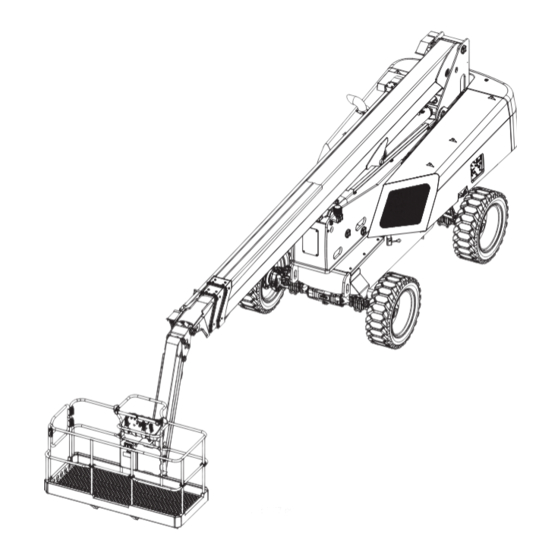
- Page 1 Operator’s Manual 85 - J ART_5798 Meets requirements of ANSI A92.20-2020 and CSA B354.6-2019. Part # 95803 January 2024 Serial Number Range 14900000 - Up...
- Page 2 January 2024 Revision History Date Reason for Update January 2024 New Release MEC Aerial Work Platforms 1401 S. Madera Avenue, Kerman, CA 93630 USA Toll Free: 1-877-632-5438 Phone: 1-559-842-1500 Fax: 1-559-842-1520 info@MECawp.com www.MECawp.com Page i 85 - J - Operator’s Manual - 95803...
-
Page 3: Table Of Contents
January 2024 Table of Contents Section 1 - Introduction . Introduction � � � � � � � � � � � � � � � � � � � � � Section 2 - Safety Safety � � � �... - Page 4 January 2024 Serial Plate � � � � � � � � � � � � � � � � � � � � � 48 Section 11 - Transport and Lifting Instructions . 49 Transport and Lifting Instructions � �...
-
Page 5: Section 1 - Introduction
Your MEC Aerial Work Platform has been designed, built, and tested to provide safe, dependable service. Only authorized, trained and qualified personnel shall be allowed to operate or service the machine. -
Page 6: Section 2 - Safety
For your safety and the safety of those around you, you must operate your machine as instructed in this manual. MEC designs aerial work platforms to safely and reliably position personnel, along with their necessary tools and materials, at overhead work locations. The owner/user/operator of the machine should not accept responsibility for the operation of the machine unless properly trained. -
Page 7: Safety Alert Symbols & Fall Protection
Section 2 - Safety January 2024 Safety Alert Symbols & Fall Protection MEC manuals and decals use symbols, colors and signal words to help you recognize important safety, operation and maintenance information. ART_6091 NOTICE RED and the word DANGER – Indicates an imminently hazardous... -
Page 8: Section 3 - Specifications
Meets requirements of ANSI A92.20-2020 and CSA B354.6-2019. Allowable ambient temperature range: -20° F to 120° F (-29° C to 49°C). Consult with MEC for operation outside of this range. Working Height adds 6 feet (2 m) to platform height. -
Page 9: Section 4 - Hazards
Section 4 - Hazards January 2024 Electrocution Hazard Electrocution Hazard ELECTROCUTION HAZARD! THIS MACHINE IS NOT INSULATED! DEATH OR SERIOUS INJURY will result from contact with or inadequate clearance from any electrically charged conductor. ART_6091 NOTICE CAUTION You must maintain a CLEARANCE OF AT LEAST 10 FEET (3.05 m) WARNING CAUTION DANGER... -
Page 10: Energized Conductor Contact Hazard
Section 4 - Hazards January 2024 Energized Conductor Contact Hazard 5000 V Max. volts Higher voltage 20000 V Min. volts 15000 V 10000 V 5000 V Lower voltage Min. volts (b) Avoid simultaneous contact across (a) Affected area areas of high potential difference CLEARANCES FROM LIVE AERIAL CONDUCTORS Spotter required... - Page 11 Section 4 - Hazards January 2024 When working in the area of energized conductors the user shall direct and the operator shall comply with the requirements to: 1) Stay at least 10 feet (3.05 m) away from power lines with any part of their body, conductive object or any part of the MEWP.
-
Page 12: Tip-Over Hazards
DO NOT exceed the maximum platform capacity. The weight of options and accessories will reduce the rated platform capacity and must be factored into the total platform load. Refer to the decals on the options or contact MEC. Driving: DO NOT drive the machine on a slope that exceeds the maximum uphill or downhill slope rating. - Page 13 NEVER alter or disable any machine components. DO NOT replace any part of the machine with anything except MEC-supplied or MEC-approved parts. NEVER use ladders or scaffolds in the platform or allow them to touch any part of the machine.
-
Page 14: Fall & Collision Hazards
Section 4 - Hazards January 2024 Fall & Collision Hazards Fall Hazards DO NOT sit, stand or climb on the platform guard rails. Maintain a firm footing on the platform floor at all times. Keep the platform floor clear of debris. ILLUSTRATION No. -
Page 15: Additional Safety Hazards
Section 4 - Hazards January 2024 Additional Safety Hazards Explosion and Fire Hazards DO NOT operate the machine in hazardous locations or locations where potentially flammable or • explosive gasses or particles may be present. Damaged Machine Hazards • Conduct a thorough pre-start inspection of the machine and test all functions before each work shift to check for damage, malfunction and unauthorized modification. -
Page 16: Section 5 - Controls & Components
Section 5 - Controls & Components January 2024 Component Locations Component Locations Engine Module Boom Engine Riser Fuel Tank Platform Chassis Platform Controls Turntable Swing Gate Control Module Hydraulic Tank Lift Gates Lower Controls ILLUSTRATION No. ART_5796 Page 12 85 - J - Operator’s Manual - 95803... -
Page 17: Platform Controls
Section 5 - Controls & Components January 2024 Platform Controls ILLUSTRATION No. ART_5790 ALWAYS check over, under and around the machine for personnel, ART_6091 NOTICE CAUTION WARNING CAUTION structures and obstructions before activating any control function and continue to watch for hazards while operating the machine. Control Description Auxiliary Power... - Page 18 ILLUSTRATION No. ART_5790 LOCK This panel contains the basic information for monitoring T: 0.0 hr 20 100 Weight off operation of the 85-J. Battery Fuel X100 Row “A” displays the pages and options available in the lower Engine Data Menu part of the screen and is controlled by the corresponding buttons on row “B”.
- Page 19 Section 5 - Controls & Components January 2024 The upper band shows: • Alarm indicator light • Steering mode selection indicator light • Parking brake active indicator light Differential block active indicator light • • Front axle block active indicator light •...
-
Page 20: Base Controls
Section 5 - Controls & Components January 2024 Base Controls ILLUSTRATION No. ART_5790 ALWAYS check over, under and around the machine for personnel, ART_6091 NOTICE CAUTION structures and obstructions before activating any control function and WARNING CAUTION continue to watch for hazards while operating the machine. Control Description Move this switch up to manually level the platform upward... - Page 21 Section 5 - Controls & Components January 2024 Select to stop operation from the lower control panel. Key Selector Switch Platform Select to operate from the platform control panel. Base Select to operate from the lower control panel. Press the green button to start the engine or to turn the engine off. Start/Stop Button Use this switch to set the engine speed when functions are enabled.
-
Page 22: Section 6 - Workplace Inspection
Section 6 - Workplace Inspection January 2024 Workplace Inspection Workplace Inspection DO NOT operate this machine until you have read and understood this manual, have performed the Workplace Inspection, Pre-Start Inspection and Routine Maintenance, and have completed all the test operations detailed in the Operating Instructions section. Inspect the workplace and determine whether the workplace is suitable for safe machine operation. -
Page 23: Section 7 - Operating Instructions & Pre-Operation Function Tests
Section 7 - Operating Instructions & Pre-Operation Function Tests January 2024 Operating Instructions & Pre-Operation Function Tests Operating Instructions & Pre-Operation Function Tests DO NOT operate this machine until you have read and understood this manual, have performed the Workplace Inspection, Pre-Start Inspection and Routine Maintenance, and have completed all the test operations detailed in the Operating Instructions section. - Page 24 Section 7 - Operating Instructions & Pre-Operation Function Tests January 2024 ILLUSTRATION No. ART_6095 Lower Control Start/Stop Button Press the green button to start the engine or to turn the engine off. ILLUSTRATION No. ART_6095 Starting Engine from Platform Controls Be sure that the upper and lower EMERGENCY STOP Switches are reset.
-
Page 25: Base Controls Operation & Pre-Operation Functions Test
Section 7 - Operating Instructions & Pre-Operation Function Tests January 2024 Base Controls Operation & Pre-Operation Functions Test ILLUSTRATION No. ART_5790 ALWAYS check over, under and around the machine for personnel, ART_6091 NOTICE CAUTION structures and obstructions before activating any control function and WARNING CAUTION continue to watch for hazards while operating the machine. - Page 26 Section 7 - Operating Instructions & Pre-Operation Function Tests January 2024 ILLUSTRATION No. ART_6096 Function Enable Switch Turn this switch right and hold to enable boom, turntable and platform operations from the base controls. ILLUSTRATION No. ART_6096 Engine Speed Select Switch Use this switch to set the engine speed when functions are enabled.
- Page 27 Section 7 - Operating Instructions & Pre-Operation Function Tests January 2024 Main Boom Lift/Lower Switch Press and hold the Boom Lift/Lower switch on the base control panel to lift or lower the main boom. ILLUSTRATION No. Test Operation ART_6096 • Turn and hold the Function Enable Switch •...
- Page 28 Section 7 - Operating Instructions & Pre-Operation Function Tests January 2024 allows manual level adjustment of the platform. Manual leveling may be used to adjust the platform within 5° of level. • Press and hold the Platform Level switch on the base control panel to manually adjust the level of the platform.
- Page 29 Section 7 - Operating Instructions & Pre-Operation Function Tests January 2024 Tilt Alarm Light ON and alarm sounding indicates an COUNTERWEIGHT UPHILL: unsafe condition. 1-- Retract Boom • STOP ALL MOVEMENT. The machine is 2-- Lower Boom not level. • Look at the diagram to determine the COUNTERWEIGHT condition of the counterweight as it relates...
-
Page 30: Platform Control Operation & Pre-Operation Functions Test
Section 7 - Operating Instructions & Pre-Operation Function Tests January 2024 Platform Control Operation & Pre-Operation Functions Test Entering The Platform Personnel shall enter and exit the platform only at the Personnel Entry Gates, and only when the boom is fully retracted and lowered. Ensure that all Personnel Entry Gates are properly closed and that the Swing Gate is latched in the closed position before operating the machine. -
Page 31: Platform Control Panel
Section 7 - Operating Instructions & Pre-Operation Function Tests January 2024 Platform Control Panel ILLUSTRATION No. ART_5790 ALWAYS check over, under and around the machine for personnel, structures and obstructions before activating any control function and ART_6091 NOTICE CAUTION continue to watch for hazards while operating the machine. WARNING CAUTION DO NOT hang anything over any control handle at any time. -
Page 32: Platform Operations Test
Section 7 - Operating Instructions & Pre-Operation Function Tests January 2024 Platform Operations Test Emergency Stop Press the Emergency Stop Switch at any time to stop all machine functions. Turn switch clockwise to reset. Depress the EMERGENCY STOP switch whenever the machine is not in operation. - Page 33 Section 7 - Operating Instructions & Pre-Operation Function Tests January 2024 Overload Indicator Light ILLUSTRATION No. ART_6097 Light ON indicates too much weight on the platform. An audible alarm will sound and all machine function will stop. Remove weight from the platform to restore function and continue. Tilt Alarm Light ON and alarm sounding indicates an COUNTERWEIGHT UPHILL:...
-
Page 34: Drive Control Lever Operation
Section 7 - Operating Instructions & Pre-Operation Function Tests January 2024 Drive Control Lever Operation Depending on the orientation of the boom and chassis, Upper Control Box the Drive and Steer functions may move the machine Directional Arrows in directions opposite of the motion of the control lever. The color- and shape-coded arrows on the control lever decal correspond to similar arrow decals on the machine chassis (see illustrations). - Page 35 Section 7 - Operating Instructions & Pre-Operation Function Tests January 2024 Drive & Steer Directional Arrows Pay careful attention to the Chassis Drive & Steer arrows for machine direction. Upper Control Box Decals Decals Platform over non-steering wheels Platform over steering wheels Decals Decals When the platform is over the steering wheels,...
- Page 36 Section 7 - Operating Instructions & Pre-Operation Function Tests January 2024 Engine Speed Select Switch ILLUSTRATION No. ART_6097 Use this switch to set the engine speed when functions are enabled. Setting this switch to low idle speed allows the operator to move the machine slowly and precisely.
- Page 37 Section 7 - Operating Instructions & Pre-Operation Function Tests January 2024 Platform Level Switch ILLUSTRATION No. ART_6097 The platform will automatically level as the boom is lifted or lowered. The Platform Level function allows manual level adjustment of the platform. Manual leveling may be used to adjust the platform within 5°...
- Page 38 Section 7 - Operating Instructions & Pre-Operation Function Tests January 2024 Test Operation • Set Steering mode to the left position: 4-Wheel Steer. Squeeze the ILLUSTRATION No. enable trigger, then press the thumb switch on top of the control lever. ART_6097 The front and rear wheels should turn in opposite directions.
-
Page 39: Auxiliary Power System & Test
Section 7 - Operating Instructions & Pre-Operation Function Tests January 2024 Auxiliary Power System & Test If primary power fails while the platform is elevated, use the Auxiliary Power System to safely lower the platform. Do not climb down the boom assembly or exit the platform while ART_6091 NOTICE CAUTION... - Page 40 Section 7 - Operating Instructions & Pre-Operation Function Tests January 2024 The Auxiliary Power System is used to lower the platform in case of primary power failure. To lower the platform, activate the Auxiliary Power Switch to run the auxiliary hydraulic pump. This function uses battery power from the auxiliary battery to lower the platform.
-
Page 41: Section 8 - Maintenance
Section 8 - Maintenance January 2024 Maintenance Maintenance DO NOT operate this machine until you have read and understood this manual, have performed the Workplace Inspection, Pre-Start Inspection and Routine Maintenance, and have completed all the test operations detailed in the Operating Instructions section. Tag and remove a damaged, malfunctioning or modified machine from service. - Page 42 Section 8 - Maintenance January 2024 Watch for makeshift “fixes” which can jeopardize safety as well as lead to more costly repair. ART_6091 NOTICE CAUTION CAUTION Inspection and maintenance should be performed by qualified personnel familiar with the equipment. Routine Maintenance IMPORTANT: The operator may perform only maintenance items on the Pre-Start Inspection Checklist.
-
Page 43: Supporting The Boom Assembly
Section 8 - Maintenance January 2024 Supporting the Boom Assembly ART_6091 NEVER perform work under the boom assembly with the platform NOTICE CAUTION WARNING CAUTION elevated without first supporting the boom assembly. DO NOT work beneath the boom assembly with the platform elevated unless the boom assembly is properly supported. -
Page 44: Pre-Start Inspection Checklist
Section 8 - Maintenance January 2024 Pre-Start Inspection Checklist The operator must conduct a Pre-Start Inspection of the machine before each work shift. DO NOT use a damaged or malfunctioning machine. Check that the operator’s manual and manual of responsibilities are in the storage container located on the platform. -
Page 45: Frequent Inspection Checklist
Section 8 - Maintenance January 2024 Frequent Inspection Checklist This checklist must be used at 3-month intervals or every 150 hours of ART_6091 NOTICE machine use, whichever occurs first. Failure to do so could result in CAUTION WARNING CAUTION death or serious injury. Frequent Maintenance Inspections should be conducted by qualified service technicians only. -
Page 46: Maintenance Inspection Report
Section 8 - Maintenance January 2024 Maintenance Inspection Report Booms (34J, 45J, 45AJ, 60J, 65J, 85J) Fleet Equipment Number Date Inspector Name Inspector Co. Model Number Address Serial Number Hour Meter Signature Machine Owner & address Maintain all service records in accordance with ANSI A92.24-2019 * If an inspection receives an “N”, remove from service. -
Page 47: Lubrication
Section 8 - Maintenance January 2024 Lubrication Operator may perform routine maintenance only. Lubrication listed as Scheduled Maintenance must be performed by a qualified service technician. Controls Module Components Removed For Clarity ADD OIL HERE DRAIN OIL HYDRAULIC FLUID HERE SIGHT GAUGE OIL LEVEL ILLUSTRATION No. -
Page 48: Section 9 - Troubleshooting
Obvious fluid leak or damaged component? • • Wires disconnected, broken, or loose? • LED should be ON. • Contact MEC Technical Support. • Technical Support • Error code at Onboard Diagnostic Center? • Contact MEC Customer Service. Page 44... -
Page 49: Section 10 - Decals
Section 10 - Decals January 2024 Decals Decals MEC - Model Info Text 1 (844) 483-4669 Manuals Brochures Warranty & More 95609 *One on the front of the chassis Page 45 85 - J - Operator’s Manual - 95803... - Page 50 Failure to adhere to the above requirements may result in death, personal injury, or property damage. Operator’s Manual inside this box. 8911 INSIDE MANUAL CASE MEC - Model Info Text 1 (844) 483-4669 Manuals Brochures Warranty & More 95609 85 - J - Operator’s Manual - 95803...
- Page 51 93855 Qty. - 1 90732 Qty. - 1 MFG DATE MODEL NUMBER SERIAL NUMBER MEWP CLASS MEC Aerial Work Platform Sales Corp. XX/XX XXXXXXXX XXXXXXXX 1401 S. Madera Ave Kerman, CA 93630, USA MAX. GROUND PRESSURE MAX. GRADIENT STOWED WARNING THIS MAX.
- Page 52 Section 10 - Decals January 2024 Serial Plate The serial plate is attached to the machine at the time of manufacture. Important information about the machine is recorded on the serial plate. The Serial Plate is located on the side of the chassis below the Base Controls.
- Page 53 Connect one end of the cable to the two front eyelets on the towing vehicle. Connect the other end of the cable to the two front eyelets of the 85-J. DO NOT ATTACH ANYTHING TO THE PLATFORM! Remove any slack from the cables to prevent movement once the brakes are released. See page 50 for instructions on how to release the brakes.
- Page 54 Section 11 - Transport and Lifting Instructions January 2024 Brake Release Procedure Unscrew lock nut 1 of power screw 2. Tighten the power screw to fit flush to disengage the brake. Repeat the operation for the other three ILLUSTRATION No. ART_6102 screws on the same axle, two screws are on the front and back of the axle.
- Page 55 Section 11 - Transport and Lifting Instructions January 2024 • Raise the jib slightly for platform ground clearance. Carefully drive the machine off or on to the transport vehicle. • • Make sure you can see the second person giving guidance. Note: The brakes are automatically released for driving and will automatically apply when the control lever is returned to neutral which causes the machine to stop.
- Page 56 Center of Gravity X Axis Y Axis 85-J Boom 17.4 in / 442mm 59.1 in / 1502mm ILLUSTRATION No. ART_4899 85 - J - Operator’s Manual - 95803...
- Page 57 January 2024 Notes Page 53 85 - J - Operator’s Manual - 95803...
- Page 58 MEC Parts Order Form Phone: 559-842-1523 Fax: 559-400-6723 Email: Parts@mecawp.com Please Fill Out Completely: Date: Ordered By: Account: Your Fax No.: Bill to: Ship to: Purchase Order Number Ship VIA ** All orders MUST have a Purchase Order Number **Fed Ex shipments require Fed Ex account number...
- Page 59 MEC Aerial Platform Sales Corp. and is found upon inspection by MEC Aerial Platform Sales Corp. to be defective in material and/or workmanship. MEC Aerial Platform Sales Corp. shall not be liable for any consequential, incidental or contingent damages whatsoever.
- Page 60 MEC Aerial Work Platforms 1401 S. Madera Avenue, Kerman, CA 93630 USA Toll Free: 1-877-632-5438 Phone: 1-559-842-1500 Fax: 1-559-842-1520 info@MECawp.com www.MECawp.com...
Need help?
Do you have a question about the 85-J and is the answer not in the manual?
Questions and answers