Delta breez Fresh VEB120S Manual
Energy recovery ventilator
Hide thumbs
Also See for breez Fresh VEB120S:
- Instructions manual (84 pages) ,
- Instructions manual (84 pages)
Table of Contents
Advertisement
Quick Links
ENERGY RECOVERY VENTILATOR
READ AND SAVE THESE INSTRUCTIONS
Address: 46101 Fremont Boulevard, Fremont, CA 94538
US Toll Free Number:
1-888-979-9889 - Technical Support
1-877-685-4384 - Customer Sales Support
www.deltabreez.com
Remove plastic bag of filter before installation
TABLE OF CONTENTS
(ERV)
MODEL VEB120S
2
5
6
8
9
17
19
20
21
25
27
28
Advertisement
Table of Contents

Subscribe to Our Youtube Channel
Related Manuals for Delta breez Fresh VEB120S


Summary of Contents for Delta breez Fresh VEB120S
-
Page 1: Table Of Contents
ENERGY RECOVERY VENTILATOR (ERV) MODEL VEB120S TABLE OF CONTENTS GENERAL SAFETY INFORMATION SPECIFICATIONS UNPACKING AND LISTING OVERVIEW INSTALLATION WIRING DIAGRAM OPERATION INSTALLATION (CONTROL PANEL) CONTROL PANEL MAINTENANCE TROUBLE SHOOTING WARRANTY READ AND SAVE THESE INSTRUCTIONS Address: 46101 Fremont Boulevard, Fremont, CA 94538 US Toll Free Number: 1-888-979-9889 –... -
Page 2: General Safety Information
GENERAL SAFETY INFORMATION Recognize and read these safety information carefully before installing and operating the ERV product. This is the safety--alert symbol when you see this symbol on the unit and in instructions or manuals, be alert to the potential for personal injury. A WARNING alert with the safety alert symbol indicates a potentially hazardous situation that could result in serious injury or death. - Page 3 GENERAL SAFETY INFORMATION 6. When leaving the house for a long period of time (more than two weeks), a responsible person should regularly check if the unit operates adequately. 7. If the ductwork passes through an unconditioned space (e.g.: attic), the unit must operate continuously except when performing maintenance and/or repair.
- Page 4 GENERAL SAFETY INFORMATION CAUTION Do not install the equipment in the following places: ● High Temperature or the Heated Place ● Wet Place ERV equipment should not be installed in places Do not install in the place where humidity is over with temperatures exceeding 104℉(40°C).
-
Page 5: Specifications
SPECIFICATIONS Unit - 22½"(572 mm) L × 19"(485 mm) W × 8⅝"(219 mm) H Dimensions Energy Recovery CORE - 10¼" (260 mm) × 10¼" (260 mm) × 7" (180 mm) Weight 36 lbs (16 kg) Power 120 Vac, 1.26 Amp Maximum. Unit Equipped with 5 ft (1.5 meter) Ground Power Cord A MERV 13 and Plastic Mesh Type at Outside Air Side, Filter A Plastic Mesh Type at Stale Air Side... -
Page 6: Unpacking And Listing
UNPACKING AND LISTING Please unpack and remove the carton carefully then follow the diagram as below to verify all unit are presented. OPENING CONTROL PANEL INSTALLATION MAUNAL ACCESSORY ENERGY RECOVERY VENTILATOR... - Page 7 UNPACKING AND LISTING PART LIST Part name Appearance Quantity MOUNTING BRACKET CHAIN CONTROL PANEL PANEL BRACKET MACHINE SCREW (M4 × 6 mm) TAPPING SCREW (T4 × 25 mm) CABLE TIES INSTALLATION MAUNAL 4P TERMINAL Interlock Wall switch 6P TERMINAL 1 of each...
-
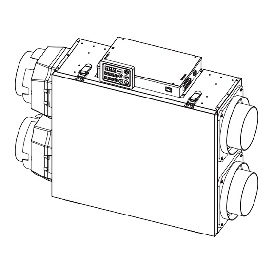
Page 8: Overview
OVERVIEW Energy recovery ventilator shall be Delta Breez model VEB120S, ECM-motor engineer runs continuously for a minimum 60,000 hours; airflow rating of from 30 to 118 CFM at 0.4" w.g. static pressure. With efficiency rating of not less than 1.22 CFM/Watt at 0.4" w.g. static pressure. Housing shall be insulated to reduce condensation and noise. -
Page 9: Installation
INSTALLATION (Wall mounted) 1. Using the hardware provided, install the 4 pcs mounting brackets mounting brackets on the unit. It is important to isolate the mounting brackets from the mounting surface to minimize vibration. 16" (406.4 mm) 2. Use the provided MACHINE SCREW (M4 ×... - Page 10 INSTALLATION (Wall mounted) 6. Using the T4 × 25 mm screws provided, 3 pcs mounting brackets secure the unit to the wall making sure that the 3 screws engage into a stud. Wall 7. Always make sure that the unit is no more than ¼"...
- Page 11 INSTALLATION (Under ceiling mounted) Using 8 screws (M4×6 mm), install the brackets on the unit, and using 4 screws (T4×25 mm) secure the unit to the ceiling, into the studs, joists or other solid materials. 4 pcs mounting brackets Wooden screw × 4 pcs T4 ×...
- Page 12 INSTALLATION (Chain mounted) 1. Adopt mounting brackets with the unit to insert the provided chains. 2. Hang the unit to the joists using the provided chains. 3. Always make sure that the unit is no more than 1/4" off level. Unit: inches (mm) Wooden screw ×...
- Page 13 INSTALLATION (Ductwork) Never install a stale air exhaust register in a room where there is a combustion device, such as a furnace, gas water heater, fireplace or any appliance or equipment that can generate gaseous contaminants, or pollutants. The negative pressure this could create in the room may impair proper WARNING evacuation of the gas or pollutants, which may have severe health consequences.
- Page 14 INSTALLATION (Ductwork) The installation method must be interlocked between HRV/ERV and Furnace/Air Handler, otherwise this is prohibited. A+B=10 ft or greater from furnace/air hander fan to C=Space a minimum of 3 ft aprat D=Space a minimum of 3 ft apart HRV/ERV fresh air to inside duct Supply Duct Fresh Air to Inside...
- Page 15 INSTALLATION (Ductwork) Method (2): Separate Room Exhaust Air Pick-Up / Fresh Exchanged Outside Air to Central System Return Air Furnace RA (Furnace) Minimum 3 ft (example, from bathrooms, dining area) Method (3): Exhaust Air from Return Duct/ Fresh Air Ducted to Supply Air Duct Backdraft Damper Minimum 3 ft Furnace...
- Page 16 INSTALLATION (Ductwork) CAUTION The exhaust outlet and fresh air inlet on the outside of the building should be at least 10 feet apart to avoid cross contamination. The Outdoor fresh air inlet must be located a minimum of 10 feet from any other exhaust vent, gas meter, outdoor grill, or source of open flame.
-
Page 17: Wiring Diagram
WIRING DIAGRAM... - Page 18 WIRING DIAGRAM Suitable for VEB120S model Unit wiring: Use 4 wire AWG #20 (min.), 100 ft length (max.). Interlock Note: Run time function is disable when Y/W/G is enable. Synchronized: Start AHU/Furnace blower when Not Synchronized: Start AHU/Furnace blower VEB120S is running not activated when VEB120S is running Thermostat Thermostat...
-
Page 19: Operation
OPERATION Follow the below step to operate the product. 1. Connect the control panel by wire, refer to INSTALLATION (CONTROL PANEL) section. 2. Connect the wire of HVAC/ AHU signal connector and RS485 connector. NOTE: No need to connect if you don’t need those function. 3. -
Page 20: Installation (Control Panel)
INSTALLATION (CONTROL PANEL) Follow the below step to operate the product. CONTROL PANEL 1. Use 2 pcs screws to secure the panel bracket. Screw M4 × 6 mm - 2 pcs 2. Control panel inserts into bracket groove. Panel Bracket WIRING PREPARATION Recommended to use the cable (AWG #14~#26), 2 ft (0.6 m) for connecting product and control panel, and the length should not be longer than 100 ft (30 m). -
Page 21: Control Panel
CONTROL PANEL Note: All Delta ERV can be controlled by control panel. The control offers the most advanced features to control your home’s ventilation with complying with California Title 24, Part 6 Sections 150.1(c)7A and 150.2(b)1E. ICON FUNCTION DESCRIPTION Power on/off Unit is enable/disable when press the button. - Page 22 CONTROL PANEL - Continues Tips for Settings Power on/off Press the button to turn on/off the unit. Boost on/off Press button one time to increase 20 min, the cycle is 20 min → 40 min → 60 min → cancel boost mode. If forcing stop it, pressing the boost button over 3 seconds.
- Page 23 CONTROL PANEL - Continues Airflow Press button to select airflow as follows. Min. 30 CFM Max. 120 CFM Press up/down button one time to change 5 CFM. the range Press to comfirm or over 10 sec is 30~120 CFM. then auto save the setting *Operation examples 1.
- Page 24 CONTROL PANEL - Continues *Run-time operation examples 1. Run 40 minutes and standby 20 minutes setting Auto Counting Auto Counting Standby 40 min 20 min Currently Continue airflow cycle 40 min 20 min 40 min 20 min 60 min 60 min 2.
-
Page 25: Maintenance
MAINTENANCE To prevent the electrical shock may result, please stop the unit and unplug it. Always wearing the gloves and glasses is recommended during the maintenance and repairs. WARNING 1. For long-term and safe use of the product, routine maintenance must be done by authorized person(s) at least every 6~ 12 months. - Page 26 MAINTENANCE - Continues Filter maintenance reminder The display will be show "F01" when the product accumulated running time reaches to 3 months and show "F02" when the product accumulated running time reaches to 6 months. Press "up and down" button simultaneously for 2 seconds to erase the error code.
-
Page 27: Trouble Shooting
TROUBLE SHOOTING Problem Possible reason Action The ERV • Is the power cord connected to the • Check the power cord is connected. doesn't host? work • Is the power cord connected to • Please check that the circuit breaker is used circuit breaker of electric panel? alone and must have a capacity of 10A or more. -
Page 28: Warranty
(including negligence), strict product liability or otherwise. 5. The warranty does not cover if user does not comply with manufacturer’s installation manual. 6. To qualify for warranty service, you must notify Delta Electronics at the address or telephone number below.
Need help?
Do you have a question about the breez Fresh VEB120S and is the answer not in the manual?
Questions and answers