Table of Contents
Advertisement
Quick Links
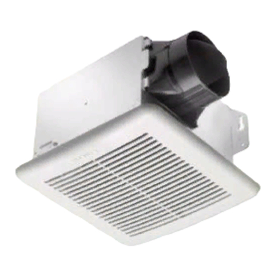
INSTALLATION AND OPERATING INSTRUCTIONS
VENTILATION FAN
READ AND SAVE THESE INSTRUCTIONS
GENERAL SAFETY INFORMATION
1.
Make sure that the electric service supply
voltage is AC 120V, 60Hz.
2.
Follow all local electrical and safety codes, as
well as the Nation Electrical Code (NEC) and the
Occupation Safety and Healthy Act (OSHA).
3.
Always disconnect the power source before
working on or near the ventilating fan, motor or
junction box.
4.
Protect the power cord from sharp edges, oil,
grease, hot surfaces, chemicals or other objects.
5.
Do not kink the power cord.
6.
Do not install the unit where ducts are
configured as shown in Fig. A.
7.
Provide suction parts with proper ventilation.
8.
This unit is UL listed for use over a bathtub or
shower when installed in a GFCI protected
branch circuit.
9.
These ventilating fans are intended for
residential usage only.
WARNING
TO REDUCE THE RISK OF FIRE, ELECTRIC SHOCK, OR
INJURY TO PERSONS, OBSERVE THE FOLLOWING:
1.
Use this unit only in the manner intended by the
manufacturer. If you have any questions, contact
the manufacturer.
2.
Before servicing or cleaning unit, switch power
off at service panel and lock the service
disconnecting means to prevent power from
being switched on accidentally. When the
service disconnecting means cannot be locked,
securely fasten a prominent warning device,
such as a tag, to the service panel.
3.
Installation work and electrical wiring must be
done by qualified person(s) in accordance with
all applicable codes and standards, including
fire-rated construction.
4.
Sufficient air is needed for proper combustion
and exhausting of gases through the flue
(chimney) of fuel burning equipment to prevent
back drafting. Follow the heating equipment
manufacturer's guideline and safety standards
such as those published by the National Fire
Protection Association (NFPA), and the American
Society for Heating Refrigeration and Air
Conditioning Engineers (ASHRAE) and local code
authorities.
5.
When cutting or drilling into wall or ceiling, do
not damage electrical wiring and other hidden
utilities.
6.
Ducted ventilating fan must always be vented to
the outdoors.
7.
Do not install this ventilating fan where air
temperature may exceed 40°C (104°F).
8.
If this unit is to be installed over a tub or shower,
it must be marked as appropriate for the
application and be connected to a GFCI (Ground
Fault Circuit Interrupter) – protected branch
circuit.
9.
These models are UL listed for tub and shower
enclosures.
10.
Do not use this unit with any other solid-state
control device. Solid-state controls may cause
harmonic distortion, which can cause motor
humming noise.
11.
Before servicing or cleaning unit, switch power
off at service panel and lock the service
disconnecting means to prevent power from
being switched on accidentally. When the
service disconnecting means cannot be locked,
securely fasten a prominent warning device,
such as a tag, to the service panel.
12.
NEVER place a switch where it can be reached
from a tub or shower.
13.
Not to be installed in a ceiling thermally
insulated to a value greater than R40. (This is
required for installation in Canada only)
Turning angle too large
Duct shrink
Too many elbows
Elbow near the body
Body
Fig. A
CAUTION
1.
For general ventilating use only. Do not use to
exhaust hazardous or explosive materials and
vapors.
2.
Not for use in cooking area. (Fig. B)
3.
This product must be properly grounded.
Cooking area
D o not install above or
inside this area
C ooking
Equipm ent
Fig. B
SUPPLIED ACCESSORIES
Part name
Appearance
Grille
Fan
Housing
Duct
(4")
MODELS:
Long Screw
(ψ4×25)
Screw
(M3x10)
1. INSTALLATIONS
MOUNT HOUSING WITH FLANGE:
1-1. To bend the housing tabs out to 90 degree and
make housing tabs contact the bottom of the
joist.
1-2. The housing mounts with 4 screws (ψ4×25).
Screw housing to joist through lowest holes in
each mounting flange, then through the other
holes.
2. DUCT CONNECTION
2-1. Insert the duct into the duct connector and tape
all ductworks connection to make them secure
and air tight.
2-2. Install the duct with a gradient 1°~2° to the
floor
outside.
Quantity
Ceiling
1
3. CONNECT WIRING
3-1. Follow all local electrical and safety codes.
1
3-2. NEVER place a switch where it can be reached
from a tub or shower.
FAN
SWITCH
1
BLK
LINE
WHT
IN
GRD
HOUSE ELECTRICAL BOX
1
3-3. Connect wires as shown in wiring diagrams.
VFB080C4A1 / VFB050C4A1
Page 1.
Outside
Inside
Tape
Duct
Body
Gradient
1°~2°
Grille
BLK
FAN
WHT
(BLK)
LIGHT/FAN ELECTRICAL BOX
4
1
Advertisement
Table of Contents

Related Manuals for Delta VFB080C4A1


Summary of Contents for Delta VFB080C4A1
-
Page 1: General Safety Information
MODELS: VFB080C4A1 / VFB050C4A1 Page 1. INSTALLATION AND OPERATING INSTRUCTIONS VENTILATION FAN READ AND SAVE THESE INSTRUCTIONS GENERAL SAFETY INFORMATION Before servicing or cleaning unit, switch power off at service panel and lock the service Make sure that the electric service supply disconnecting means to prevent power from voltage is AC 120V, 60Hz. -
Page 2: Specifications
Do not allow water to enter motor. point. Do not soak resin parts in water over 60°C. 3. Delta Electronics shall not be liable for any indirect, incidental, consequential, punitive, or CLEANING: special damages arising out of or in connection with products use or performance, regardless of Open lens cover.
Need help?
Do you have a question about the VFB080C4A1 and is the answer not in the manual?
Questions and answers
The LED on my fan is blinking green 12 times. What does this mean?