
Related Manuals for Tucsen Dhyana 2100


Summary of Contents for Tucsen Dhyana 2100
- Page 1 Dhyana 2100 Camera User Manual Copyright (c) 2011-2025 Tucsen Photonics Co., Ltd All rights reserved.
-
Page 2: Table Of Contents
Contents 1. Read Before Use ......................1 2. Cautions ........................2 3. Packing List .........................3 4. Product Specifications ....................4 4.1 Camera Introduction ..................... 4 4.2 Main Features ........................ 4 4.3 Parameter Specifications ..................... 5 4.4 Spectral Response ......................6 4.5 Mechanical Structure Specifications ................7 5. -
Page 3: Read Before Use
This camera instruction document contains the basic information, product features, function introduction and maintenance of the camera. It is an internal document and published content of TUCSEN, which can make it easier for users to use TUCSEN cameras. This document is published only for the above purposes and does not constitute a license, transfer or any other right of the owner. -
Page 4: Cautions
2. Cautions Operation and Usage Do not drop it. Disassemble, repair or replace the internal components by yourself. Otherwise, camera components may be damaged or electric shock may be caused. If liquids such as water, beverages or chemicals enter the equipment, ... -
Page 5: Packing List
is turned off. Otherwise, the camera may be damaged. 3. Packing List Item Name Specification / Model Quantity Pictures sCMOS Camera Dhyana 2100 1 × Adapter Ring F mount adapter ring 1 × Power Adapter 24V/6.67A 1 × Software and driver USB Flash Drive 1 ×... -
Page 6: Product Specifications
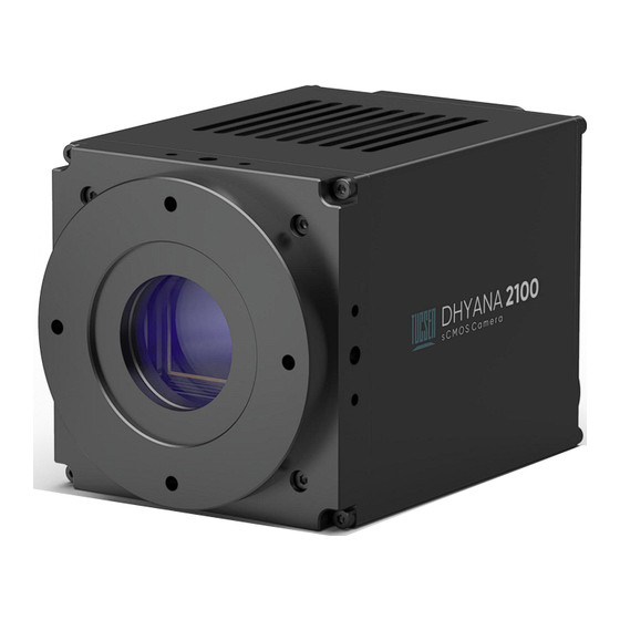
CoaXPress 4× Cable External trigger HR10A-7P-4P 1× Cable 4. Product Specifications 4.1 Camera Introduction The Dyhana 2100 is an ideal combination of high speed and high resolution. It not only has a speed of 450 frames/second at 21 million full resolution, but also has designed a high-speed binning mode especially for weak light applications, with higher sensitivity and dynamic range, and a speed of 1725 frames/second @ 5 MP. -
Page 7: Parameter Specifications
Flat field correction Dark field correction Support test image output Camera temperature monitoring 4.3 Parameter Specifications Parameters Properties Camera Model Dhyana 2100 Sensor Type Front-illuminated CMOS Shutter Type Global shutter Color/Mono Mono Effective Area 23.04 mm x 18.43 mm... -
Page 8: Spectral Response
DC 24 V / 6 A Power ≤ 120 W Consumption Dimensions 95 mm x 95 mm x 140.5 mm Weight <2kg Software Samplepro C/C++/C# Compatible Windows/Linux Systems Operating Temperature 0~40℃, Humidity 10~85% Environment 4.4 Spectral Response Dhyana 2100 spectral response curve Page 6... -
Page 9: Mechanical Structure Specifications
4.5 Mechanical Structure Specifications Unit: mm,Diameter: ø. Page 7... -
Page 10: Installation
The interfaces and functions of the Dyhana 2100 camera are shown in Figure 5-1 and Table 5-1 below. Figure 5-1 Location of the Dhyana 2100 Camera Interface Table 5-1 Functions of each interface of the Dyhana 2100 camera Part Name... -
Page 11: Camera Installation
(2) The trigger level is judged to be high when it is higher than 2.6V, low when the trigger level is lower than 0.6V, and indeterminate from 0.6 to 2.5V, with possible erroneous trigger states. 5.2 Camera Installation Dhyana 2100 ① Power Adaptor CXP Data Cable DC 24V/6.67A... - Page 12 Fig. 5-2 Connection Diagram of Dyhana 2100 1. Power Connection: Use the factory matched 24V/6.67A power supply; 2. Water Cooling System Connection (if the camera is in air cooling mode, please omit this step): Use the recommended matching water circulation system to connect the two water circuit ports of the camera, turn on the water circulation for heat dissipation and ensure that the water circuit is smooth without water leakage, and the recommended water temperature is 25℃...
- Page 13 Camera KAYA Frame Grabber Euresys Frame Grabber Power on the camera, and open the SamplePro software after the camera is started; If water cooling is used alone, the water circulation system must be started and operated normally before the camera is started to avoid overheating; ...
-
Page 14: Frame Grabber Installation
successfully ->turn off the computer ->turn on the computer ->firmware of the frame grabber takes effect; Firmware takes effect when the computer is powered off and then turned on instead of restarting the computer. 5.3 Frame Grabber Installation Turn off the computer and open the cover of the computer, as shown in the following figure. -
Page 15: Driver Installation
Figure 5-3 Computer motherboard diagram Table 5-2 Maximum Transmission Rate Corresponding to Different PCIe Slots PCIe 250MB/s 1GB/s 2GB/s 4GB/s 500MB/s 2GB/s 4GB/s 8GB/s 985MB/s 3.9GB/s 7.8GB/s 15.7GB/s 5.4 Driver Installation 1. Kaya Frame Grabber Driver Installation Note: Kaya frame grabber only supports Win10 (x64) in Windows 1.1 Double click the KAYA frame grabber driver to start the installation 1.2 Click "Next"... - Page 16 1.3 Select the installation location of the drive, press the default configuration, and click "Next 1.4 Continue to click "Next" according to the operation prompt Page 14...
- Page 17 1.5 Continue "Next 1.6 Click "Install" to upgrade Page 15...
- Page 18 1.7 Click "Install" to continue the installation after upgrading Page 16...
- Page 19 1.8 Click "Finish" to proceed to the next step 1.9 Choose to restart the computer immediately, and click "Finish" to restart the computer to complete the installation. Page 17...
- Page 20 2. Euresys Frame Grabber Driver Installation Note: Euresys frame grabber supports Win7/Win10 systems in Windows 2.1 Taking the installation under Win10 as an example, double-click the corresponding driver to start the installation, and click "Next" to proceed to the next step 2.2 Wait for the installation to complete Page 18...
-
Page 21: Software Installation
2.3 Click OK after installation 5.5 Software Installation The Samplepro software comes with the USB flash drive, which can be directly decompressed for use. Note: 1. When the Samplepro software is started for the first time, run it as the administrator, and then double-click the software directly;... - Page 22 temperature should not exceed 5℃. 3、Environment Under improper environmental conditions, condensation water may appear in the water valve and water pipe, which may damage the equipment. To ensure the normal operation of the equipment, the temperature difference between ambient temperature and water temperature can refer to the appendix of this section.
- Page 23 Appendix: Humidity / % ℃ Fig. 5-6 Dew Point Corresponding to Temperature and Humidity Page 21...
-
Page 24: Software Instructions
6. Software Instructions 6.1 Software Start Interface Double click SamplePro to open the camera software. The software start interface is shown in Figure 6-1. Wait until the loading is completed. The boot time varies with different frame grabbers. (The startup time of Euresys frame grabber is about 10s, and that of KAYA frame grabber is about 20s) Figure 6-1 Software Start Interface 6.2 Window Composition... - Page 25 Preview Window The preview window displays the camera's real-time picture under the stream module. The preview window supports real-time zooming. Users can zoom in or out of the preview window by using the mouse wheel according to actual needs. The lower left corner of the preview window will display the pixel gray value, coordinates and image resolution of the mouse position in the real-time screen according to the mouse, as shown in Figure 6-2-1.
-
Page 26: Image Capture
Figure 6-2-2 Image Adjustment Module 6.3 Image Capture As shown in Figure 6-3, the image capture module supports the basic shooting and recording functions of the camera. Figure 6-3 Image capture module Capture: Click the button to take a picture; ... -
Page 27: Camera Control
Total Frames: User-defined selection of the number of pictures taken, and 1 picture is saved by default; Record: Start recording manually; Stop Record: Stop recording manually; 5433.1MB/s 272.64fps: Display camera real-time speed and frame rate. 6.4 Camera Control The main functions of the camera are developed under this module, and the camera plotting mode is controlled here, as shown in Figure 6-4. -
Page 28: Devicecontrol
: Operator mode selection, including Beginner, Expert and Guru. Please select Guru mode to use all camera functions. 6.4.1 DeviceControl Display camera basic information (read-only), UserID editing, camera reset, Device temperature, Sensor Board temperature, and Sensor temperature in real time. As shown in Fig. -
Page 29: Imageformatcontrol
: The device reset button eliminates the need to power off the camera, and the camera automatically loads the default parameter configuration; Fig. 6-4-2 : Display Device temperature in real time (read-only); : Display Sensor temperature in real time (read-only); ... - Page 30 HeightMax: Display the maximum vertical resolution of the current image in real time (gray read-only); Note: Normal resolution is 5120 × 4096, FastBinning resolution 2560 × 2016; Width: Horizontal width setting of the current image, the minimum input is 128, and the step is 32;...
-
Page 31: Acquisitioncontrol
Direction→ Fig. 6-4-4 6.4.3 AcquisitionControl Set the camera frame rate, trigger mode, exposure mode, trigger filter, etc., as shown in Figure 6-4-5. Fig. 6-4-5 Acquisition Start: In stream mode, counting restarts after plotting is paused; Acquisition Stop: In stream mode, the current software plotting is suspended and counting stops;... - Page 32 AcquireFrameRateMax: Displays the maximum frame rate that the camera can set under the current parameters (gray read-only); AcquireFrameRate: Set the current frame rate of the camera, the minimum setting is 0.095Hz; FrameRateMode: When in On state, the frame rate setting takes precedence. At this time, the maximum exposure time s=0.95/frame rate can be set;...
-
Page 33: Analogcontrol
Note: The default parameter 1 is recommended for TriggerFrameNum. TriggerFrameNum > 1 may trigger frame loss. TriggerSoftware: Software trigger, click the button to trigger; TriggerSource: Supports ExternalTrigger and SoftTrigger. When TriggerMode is in On status, users can select ExternalTrigger and SoftTrigger according to trigger requirements;... - Page 34 LUTIndex: INPUT value. After input, the output value corresponding to the applied curve will be automatically loaded. The range is 0~4095; LUTValue: OUTPUT value, loaded according to the entered LUTIndex value, which can be manually modified and saved, ranging from 0 to 4095; ...
-
Page 35: Digitaliocontrol
The application steps are as follows: ① Input the required gamma value first; ② Click Apply to apply the currently selected curve; ③ Click DownLoad to configure the curve to the camera. 6.4.6 DigitalIOControl The camera trigger output module is shown in Figure 6-4-9 Fig. -
Page 36: Dpc
TECCutyFactory: TEC power gear, adjustable by 0~100%; CoolOperationTemperature: Refrigeration target temperature, adjustable range - 30~50 ℃, default 10 ℃. 6.4.8 DPC Fig. 6-411- DPCMode: Static bad pixel correction enable switches Off and On; DPCLevel: Static bad pixel correction gear selection, supporting Low, Middle and High;... - Page 37 the average brightness value of the current image). After enabling, click PRNUGenerate under uniform light in the bright field to automatically generate PRNU correction data; PRNUTargetLevel: Manual PRNU mode. After unchecking the automatic PRNU mode, adjust the brightness of the bright field uniform light to the set gray value by setting the PRNU gray value.
-
Page 38: Coaxpress
6.4.10 CoaXPress Fig. 6-413- : CXP starts the connection selection by default; : CXP mode switching, default CXP12_ X4, it needs to be switched in the live state, and the grey cannot be switched in the stop state of the stream mode. - Page 39 UserSetSelector: User settings storage, providing three configurations: Default, User Set1 and User Set2; UserSetLoad: Default, user set1 and user set2 parameters selected for camera loading; UserSetSave: Save the modified parameter configuration in the selected User Set1 and User Set2 groups; ...
-
Page 40: After Sales
3. Contact professionals for technical support: TEL: 400-075-8880 0591-88194580-811 Email: service@tucsen.com Or log in to TUCSEN official website and leave a message: http://www.tucsen.com. Please prepare the following information in advance: 1) Camera model and S/N (product serial number); 2) Software version number and computer system information;...
Need help?
Do you have a question about the Dhyana 2100 and is the answer not in the manual?
Questions and answers