
Related Manuals for Leyard MGS Series


Summary of Contents for Leyard MGS Series
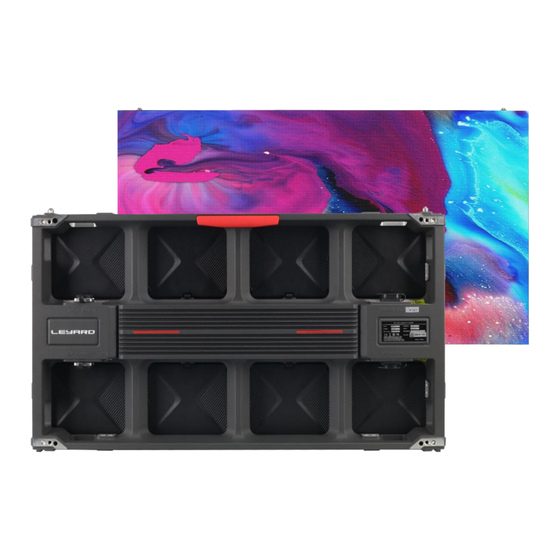
- Page 1 MGS Series product manual MGS Series Outdoor Full Color Fine Pitch LED Display Unit Product Installation Manual...
-
Page 2: Copyright Statement
MGS Series product manual Copyright Statement Copyright © Leyard Optoelectronics is the legal owner of the right to exercise this copyright in accordance with the law. This publication may not be excerpted, reproduced, copied, translated, edited, published or stored in a retrieval system for any other use by any individual or organization in any form without the signed permission of Leyard Optoelectronics. -
Page 3: Revision History
MGS Series product manual Revision History Revision Revise Brief description of the amendments date d by The product manual issued for the first time 2023-04-26 Lingke Made by: 夏令柯 Checked by: Approved by:... -
Page 4: Table Of Contents
3.11 Calculation of total power consumption of display screen ..................24 3.12 Power distribution cabinet cable model selection ......................24 3.13 Leyard engineering power distribution cabinet model description ................25 3.14 Example distribution connection schematic ........................27 4.0 Product installation solution ....................28 5.0 Common faults and solutions .................... -
Page 5: Product Overview
MGS Series product manual 1.0、 Product overview MGS series products are a new generation of outdoor fine-pitch display units, full flip light-emitting chips, low power consumption, high luminous efficiency, widely used in square advertising, shopping mall windows, bus stations and so on. -
Page 6: Technical Parameters
MGS Series product manual black screen 1.11 Technical parameters Item MGS1.2 MGS1.3 MGS1.5 MGS1.6 MGS1.8 MGS2.0 Fully Fully Fully Fully Fully Fully LED Configuration flipped flipped flipped flipped flipped flipped 3-in-1 3-in-1 3-in-1 3-in-1 3-in-1 3-in-1 Pixel pitch(mm) 1.25 1.33 1.53... - Page 7 MGS Series product manual Vertical viewing angle( °) Deviation of LED Luminance Center <3% (after calibration) Brightness uniformity (after ≥97% calibration) Color uniformity No more than ±0.003Cx,Cy (after calibration) Contrast ratio 10000:1 Peak power consumption 150;651 (W/m ) Average power...
-
Page 8: Display Unit Structure Function Analysis
MGS Series product manual Storage Temperature (℃) -30 -- 60 Operation 10 -- 80% no condensation Humidity (RH) Storage Humidity 10 -- 85% no condensation (RH) Inst alla Front installation, ✅ ✅ ✅ ✅ ✅ ✅ rear installation Full front... - Page 9 MGS Series product manual 4- Φ 7.5 4-M6 thread hole through hole As shown in the figure, the display unit cabinet has two kinds of mounting holes- front and rear mounting holes. Standard front-installation applies M6 x 16 mm hexagonal cylinder head screws;...
- Page 10 MGS Series product manual As shown in the figure below, inside the red coil is adjustment of all directions of 6 axis adjustment function. direction adjustment area direction adjustment area direction adjustment area direction direction adjustment area adjustment area direction...
- Page 11 MGS Series product manual In the installation process, the use of 6 axis adjustment function can effectively improve the installation accuracy of LED screen; The following is a detailed description of the 6 axis adjustment: X direction adjustment. There is one M6 x 35mm cylindrical head screw and one M6 hexagonal Kimi screw on the upper right and lower right sides of the display unit respectively.
-
Page 12: Introduction To Product Maintenance
MGS Series product manual Allen key Tighten Allen key Push off Y direction tightening gap adjustment screw Y direction pushing off distance adjustment screw Z direction adjustment, the 4 corners of the cabinet mounting hole have the Z direction adjustment function. This function can adjust display unflatness between unit cabinets caused by installation environment problems. - Page 13 MGS Series product manual First, remove the LED module from the front of the display unit cabinet with the MGS electric front maintenance tool,remove the back cover of the LED module with a Phillips screwdriver, repair the internal components of the module;See below for details:...
- Page 14 MGS Series product manual Repeat the first step. After removing all the LED modules, remove the front cover of the power cabinet. After removing the front cover, you can see the drive board of this product.After removing the fixing screw on the drive board, take out the drive board, check and repair the drive board.
- Page 15 MGS Series product manual After completing all or any of the above steps. If the product returns to normal, install the product in an orderly manner, carefully check whether the disassembled area is still water proofing . If there is an exception, you need to handle the exception, and then install and use the product.
-
Page 16: Control System
MGS Series product manual 2.0、 Control system 2.11 Receiving card The physical appearance of the receiving card is shown in the following figure: Product model:X300-II / LEADSHOW 5G receiving card LSR8C-1 2.12 Interface description Indication Color Status Description light The receiving card works normally, the network... -
Page 17: Sending Box
MGS Series product manual light 2.13 Sending box Indication light Equipment running indicator, slow flashing when there is no video source(frequency is on for 2 seconds, off 2 for seconds) Normal flashing when there is video source input (approx. 1 second flashes... - Page 18 MGS Series product manual Indication Same as the front panel light Output OUT1-44 network port output interface USB connection to computer, USB control interface Control interface UART IN, OUT cascade input and output Functional LIGHT SENSOR interface interface Power AC-100-240V-50/60HZ AC power interface supply 2.14...
- Page 19 MGS Series product manual MGS1.2 Schematic diagram of single signal routing Example 2: MGS1.5 single cabinet unit resolution is 416x232, a network cable can load up to six cabinets (rectangular) , support left and right, up and down connection, take 2K send card as an...
- Page 20 MGS Series product manual MGS1.5 Schematic diagram of single signal routing Example 3: MGS1.8 single cabinet unit resolution is 344x192, a net cable can load up to 9 cabinets (rectangle) , support left and right, up and down connection, take 2K send card as...
- Page 21 MGS Series product manual MGS1.8 Schematic diagram of single signal routing 2.15 Schematic diagram of dual signal routing Example 1: MGS1.2 single cabinet unit resolution is 512x288, a network cable loads up to 4 cabinets (rectangle) , support left and right, up and down connection, take 2K send card...
- Page 22 MGS Series product manual as an example, 2k area arrangement is 3x3, the total resolution is 1536 * 864, see below: MGS1.2 Schematic diagram of dual signal routing Example 2: MGS1.5 single cabinet unit resolution is 416x232, a network cable loads up to six...
- Page 23 MGS Series product manual MGS1.5 Schematic diagram of dual signal routing Example 3: MGS1.8 single cabinet unit resolution is 344x192, a net cable loads up to 9 cabinets(rectangle) , support left and right, up and down connection, using 2K send card as...
- Page 24 MGS Series product manual MGS1.8 Schematic diagram of dual signal routing...
-
Page 25: Description Of Power Distribution Loading
MGS Series product manual 3.0、 Description of power distribution loading 3.11 Calculation of total power consumption of display screen Total display power = total screen power + total power of peripheral device + total power of heat dissipation device Power of switching power supply: output voltage (V) × output current (A) = power of single power supply (W) Total screen power:... -
Page 26: Leyard Engineering Power Distribution Cabinet Model Description
(sheath layer with a layer of metal skin) , commonly used number: YJV22-or YJV23-, etc. , this cable bending radius is large, inconvenient laying. 3.13 Leyard engineering power distribution cabinet model description Power 20KW... - Page 27 MGS Series product manual distribution cabinet dimension MM (W) × (H) × (D) Power distribution cabinet weight (KG) Installation Hanging method 供电方式 Power AC380V three-phase five-wire system supply mode 配电柜进线 Inlet cable of power YJV4×25+1× YJV4×35+1× YJV4×35+1× distribution YJV5×6 YJV5×10 YJV5×16...
-
Page 28: Example Distribution Connection Schematic
The power per step is more than 8KW. The cable from the distribution cabinet to the display screen generally adopts RVV3*4MM ² cable (branch line). For MGS Series products, a single RVV3 * 4MM ²(branch line) loads no more than 18 PCS of MGS cabinets. -
Page 29: Product Installation Solution
MGS Series product manual 4.0、 Product installation solution 4.11 Preparation before installation Before installation, the necessary tools, general installation tools, installation accessories and work protective equipment should be prepared. The necessary tools and installation accessories should be provided by the project, general installation tools and work protective equipment should be equipped by the construction personnel themselves. - Page 30 MGS Series product manual Tool Tool Rubber hammer Active wrench Tape measure Screwdriver name Protective equipment: Protective equipment Name Safety helmets Seat belt buckle Protective Gloves Protective apron Note: as for rear installation with connection plate mounted across the square tube, the project leader needs to choose the length of the installation screw according to the actual needs of the on-site steel structure.
- Page 31 MGS Series product manual LED cabinet Squar unit e steel LED cabinet Cabinet tube unit connection plate Mounting Cabinet Mounting screw connection plate screw 4.12 Introduction of installation solution Conventional aluminum profile structure front installation solution: This installation solution is suitable for small area LED screen projects, the screen had better be hanged onto the building wall.
- Page 32 MGS Series product manual 2. Arrange the pre-embedding in advance according to the project design drawings and the conditions on site, ; For the layout of embedding, you need to consider the self-weight load of the LED screen and the installation structure, determine the safety and reliability of the embedded point by combining with the local natural load standard value and anti - seismic standard value.
- Page 33 T-nut block MGS Series product manual Allen key Aluminum frame Allen key 5. Install all the cabinet unit in sequence according to the figure above. 6. Connect the relevant cables according to the project power distribution system diagram and system connection diagram.
- Page 34 MGS Series product manual installation steps for the aluminum profile structure: 1. Common front-installation accessories. The accessories will provided by the factory. Please count the number of accessories before installation, as shown in the table below: Accessory M6*60 cylindrical Cabinet...
- Page 35 MGS Series product manual gradually. For rear installation, the module of display unit need not be removed, and the square steel tube can be crossed directly from the rear of the cabinet. The cabinet can be locked with the corresponding screws of the project. If there is...
-
Page 36: Common Faults And Solutions
MGS Series product manual 5. Connect the relevant cables according to the project power distribution system diagram and system connection diagram. 6. After the electrical test with the multi-meter is finished, assemble the module back to the cabinet unit, adjust the flatness, and carry out power adjustment. - Page 37 MGS Series product manual problem. 3.Display unit cascade cable transmission issues. 4. If the control board is replaced, the display unit image still can not be connected with the surrounding, you need to use the software to set the corresponding address coordinates and brightness color values.
- Page 38 MGS Series product manual state 3.If the problem still exists after the above two-step settings, the judgment may be because of LED module or control board circuit issues, you can replace the LED module or control board, adjust the coordinate, color, brightness , so that it is consistent with the the image color of the whole screen.
-
Page 39: Product Usage Notes
MGS Series product manual 6.0 Product usage notes 6.11 Notes ① As LED and CMOS integrated circuits are electrostatic sensitive devices, it is necessary to prevent static electricity when using LED modules. Static electricity can be effectively prevented Personnel in contact with the product must wear a grounding electrostatic bracelet or ... - Page 40 MGS Series product manual When repairing and soldering CMOS devices, the temperature of the electric soldering iron must be kept below 315 °C, the soldering time should not exceed 3s, and the number of welding times should not exceed three times;...
-
Page 41: Standard And Method Of Full Screen Acceptance
MGS Series product manual damage to the module; ⑨ Any product, under certain conditions, may fail. Users are responsible for complying with safety standards and taking safety measures to avoid potential risks of failure, personal injury or property damage. 6.12 Standard and method of full screen acceptance ●... - Page 42 MGS Series product manual protection belt facilities and effectively grounded, the power distribution cabinet is required to be equipped with surge protector, and the lightning protection facilities are inspected every six months.
Need help?
Do you have a question about the MGS Series and is the answer not in the manual?
Questions and answers