
Related Manuals for Leyard TWF Series


Summary of Contents for Leyard TWF Series
- Page 1 LED Display Construction Acceptance Specification TWF Series LED Display Unit User Manual Date: April 2017...
- Page 2 Specification Copyright Statement Copyright © Leyard Optoelectronic Co Ltd. is the legal copyright owner of this document. Without Leyard’s prior permission, any other person or organization shall notextract, reprint, copy, translate, edit, publish or savethe whole or any part of it into a retrieval system or use it in any other place in any form.
- Page 3 LED Display Construction Acceptance Specification Safety Tips 1.Please read these safety tips carefully before installation. 2.Keep these safety tips properly; 3.Comply with all these safety tips; 4.Do not install the apparatus in dusty or liquid dripping environment, and this requirement is especially applicable to the indoor displays; 5.Do not expose the indoor display and apparatus to water or mist;...
- Page 4 LED Display Construction Acceptance Specification working temperature of the apparatus exceeds 40 ℃, it is necessary to use air conditioning for ventilation and heat dissipation, so as to ensure the working temperature range is consistent with the required value. 17.The apparatus should be connected to a power grid with a protective earth connection;...
- Page 5 LED Display Construction Acceptance Specification Revision History Date of Revised Description of Modification Revision...
-
Page 6: Table Of Contents
Chapter 3Control System ..................... 18 ......................18 NTRODUCTION OF RODUCT Main Components of TWF Series Display Unit ..................18 Controller ..............................19 LED Module ..............................20 Cascade Power Supply and Signal Board of LED Module................21 Cascade HDMI Signal Line of Display Unit ....................21 Cascade RJ25 Serial Line of Display Unit .................... - Page 7 User Manual for TWF Series LED Unit Introduction ..............................27 Operating Environment ..........................27 ................27 OFTWARE NSTALLATION AND NINSTALLATION Installation ..............................27 Uninstallation .............................. 30 ......................... 32 III. OFTWARE NTERFACE ................. 33 UIDELINES FOR PERATION OF OFTWARE Communication Settings ..........................34 Basic Controls ..............................
-
Page 8: Chapter 1Twf Series Led Unit
4. Highly integrated hardware: No external LED controller is required and the controller and drive board are put together, which makes the maintenance much easier. At present, the specifications of TWF series LED display unit for the splicing wall are listed in the following table: Physical Unit Dimensions W×... -
Page 9: Technical Parameter Table
User Manual for TWF Series LED Unit III Technical Parameter Table The following parameters are given with TWF012AS as an example. Refer to the product specifications for the parameters of other products. Parameter TWF012AS Pixel structure SMD 3in1 LED 1.25... - Page 10 User Manual for TWF Series LED Unit Working humidity range (RH) 10~80% (non-condensing) Storage humidity range (RH) 10~80% (non-condensing) ~ 5 ~...
-
Page 11: Chapter 2 Installation
User Manual for TWF Series LED Unit Chapter 2 Installation Dimensional Figure of Product 1. Dimensional Figure of Display Unit Unit: mm Three-view Figure of TWF Display Unit 2. Dimensional Figure of Installation Structure There are four types of installation structures, i.e. 1*1, 1*2, 2*1 and 2*2,and their dimensional figures are as below: Unit: inch (upper figure);... - Page 12 User Manual for TWF Series LED Unit ~ 7 ~...
- Page 13 User Manual for TWF Series LED Unit ~ 8 ~...
-
Page 14: Display Unit And Installation Structure
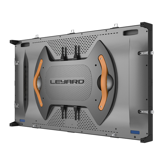
User Manual for TWF Series LED Unit Display Unit and Installation Structure ~ 9 ~... - Page 15 User Manual for TWF Series LED Unit TWF series display unit has a unique structure based on which the front installation of the whole unit may be achieved. The installation should be completed by four layers, namely: A. LED display unit, fixed with Layer B through four Z-axis fine adjustment screws.
- Page 16 User Manual for TWF Series LED Unit Layer A and Layer B belong to the components of the display unit Layer C and Layer D belong to the installation structure ~ 11 ~...
-
Page 17: Adjustable Mechanism
User Manual for TWF Series LED Unit The installation structure is provided with left and right connecting pieces (left) and upper and lower connecting pieces (right) Splicing figure for connection of the four types of installation structures, i.e. 1*1, 1*2, 2*1 and 2*2 via connection pieces III. - Page 18 User Manual for TWF Series LED Unit are two adjustment points respectively on the left side, right side and top of the structure in Layer C. Fixing Holes and Adjustable Structure of the Installation Structure ~ 13 ~...
-
Page 19: Structure Adjustment Of Display Unit
User Manual for TWF Series LED Unit XY four-axis adjustment mechanism 2. Structure Adjustment of Display Unit Once Layers A and B layer, as a integrated display unit component, are completely installed, Layer B will be locked with Layer C and Layer D. In the subsequent maintenance, it only needs to remove the LED display unit in Layer A. -
Page 20: Installation
User Manual for TWF Series LED Unit Diagram for display unit separated from the structure layer IV. Installation 1. Necessary Tools Level ruler, tape measure, power tool with 10 mm sleeve head and large cross screwdriver, large slotted screwdriver, 3mm hexagon tool and special magnetic tool. - Page 21 User Manual for TWF Series LED Unit ~ 16 ~...
- Page 22 User Manual for TWF Series LED Unit ~ 17 ~...
-
Page 23: Chapter 3Control System
Besides, there are also the control ports including RJ45 network port and RJ25 serial port. 1. Main Components of TWF Series Display Unit The connection relations of the main components of TWF Series Display Unit are as shown in the figure below: ... -
Page 24: Controller
User Manual for TWF Series LED Unit 2. Controller The illustration for the internal LED controller interface of the TWF series display unit is as shown below: ① RJ25 serial signal input 1: main channel signal; ② RJ45 network signal input: supports the standard TCP / IP protocol, and the external devices like computer control and adjust the parameters of the TWF display unit via this port;... -
Page 25: Led Module
User Manual for TWF Series LED Unit ⑥ RJ25 serial port signal output 1: used for cascade of control signals between TWF display units; ⑦ RJ25 serial signal input 2: backup control signal; ⑧ HDMI IN2 video signal input 2: an alternate input for HDMI video signal, with the priority lower than HDMI IN1. -
Page 26: Cascade Power Supply And Signal Board Of Led Module
User Manual for TWF Series LED Unit 4. Cascade Power Supply and Signal Board of LED Module 5. Cascade HDMI Signal Line of Display Unit Cascade HDMI Signal Line of Display Unit: There are locking devices on both sides of HDMI terminal, which may fit with the lock of the display unit structure, playing a role in fixing the interface so as to improve the stability of the video signal transmission between the display units. -
Page 27: Splicing Mode And Wiring Diagram
The standard DVI/HDMI cable should be used for connection between the DVI/HDMI signal directly output by the broadcast control computer and other video sources and the HDMI input interface of the TWF series display unit. See the figure below (for reference only). HDMI Cable DVI-HDMI TransferCable 2. -
Page 28: Connection Of Power Cord
User Manual for TWF Series LED Unit 3. Connection of Power Cord Usually, the AC power is upward transformed from the bottom of each line in the form of cascade. The DC output cable is connected to the input port of the control panel, AC 220V may be cascaded with up to 16 display units;... -
Page 29: Remote Control Wiring Diagram
User Manual for TWF Series LED Unit System Wiring Diagram for 4× 4 Splicing(Rear View) 5. Remote Control Wiring Diagram Use the HDMI signal cable to directly connect the video source apparatus and the display screen. The maximum length of the video communication cable is usually 15m, and the optical fiber transmission shall... -
Page 30: Common Faults And Troubleshooting Measures
User Manual for TWF Series LED Unit DVI female connector- the HDMI male connector transfer cable DVI Optical Transceiver Interface Diagram III. Common Faults and Troubleshooting Measures Common Faults and Troubleshooting Measures Description of Fault Troubleshooting Measures 1. No image is displayed 1. - Page 31 User Manual for TWF Series LED Unit fault is not eliminated in the previous two steps, connect the LCD display at the failed display unit to check the HDMI signal. Try to replace the HDMI signal cable. If the image of the display unit with replaced panel...
-
Page 32: Chapter Iv Control Software
1. Introduction The Leyard LED Control control software is used for system debugging, daily operations, and production testing of TWF and TWS series LED displays made by Leyard Optoelectronic Co Ltd. 1. Operating Environment Operating system: currently only supports Windows 7 version. - Page 33 User Manual for TWF Series LED Unit ~ 28 ~...
- Page 34 User Manual for TWF Series LED Unit ~ 29 ~...
-
Page 35: Uninstallation
User Manual for TWF Series LED Unit 2. Uninstallation Select the software in the control panel and perform the uninstallation. ~ 30 ~... - Page 36 User Manual for TWF Series LED Unit ~ 31 ~...
-
Page 37: Software Interface
User Manual for TWF Series LED Unit III. Software Interface Double-click the desktop shortcut icon to activate the software. The software interface is divided into five parts: a is a menu bar, containing function menu “Functions” and language menu “Language”. The functional module of the function menu is in Working Area C;... -
Page 38: Guidelines For Operation Of Software
User Manual for TWF Series LED Unit IV. Guidelines for Operation of Software When display units are mounted and cables connected for a piece of screen, the next work is to configure it via software. Steps ①~⑥ show the operations for splicing a screen with standard resolution. Initial steps ①, ②... -
Page 39: Communication Settings
User Manual for TWF Series LED Unit 1. Communication Settings There are two types of communication, i.e. network communication and serial communication between the control computer and the LED display. Select the appropriate communication type according to the actual communication mode. The network control is recommend. - Page 40 User Manual for TWF Series LED Unit Set the two switches on the transfer board to the direction near the RJ25 port. See the figure below. RJ25 The communication interval and communication waiting time are defaulted as 1ms, and they do not need to be changed.
-
Page 41: Basic Controls
User Manual for TWF Series LED Unit 2. Basic Controls Basic Controls Page HDMI input settings, usually set as “Auto” mode; Brightness adjustment of display unit, used to adjust the percentage of color temperature and brightness ; ... -
Page 42: Advanced Controls
User Manual for TWF Series LED Unit 3. Advanced Controls Advanced Controls Page GAMMA settings, used to save, modify and re-upload GAMMA sent to the LED screen; Read display unit parameters such as MCU and FPGA; Read the version number of LED module;... -
Page 43: Seam Correction
User Manual for TWF Series LED Unit 5. Seam Correction This function is designed to perform the optical compensation and correction on the bright or dark line at the edge of the module. Enter the password “installer” after the “Seam Correction”... - Page 44 User Manual for TWF Series LED Unit Six-steps operations: Select the IP display unit to be corrected; Read the correction data from the control panel; Back up the correction data and save it into the computer; The review window pops up. Operation Methods: A.
-
Page 45: Factory Settings
User Manual for TWF Series LED Unit Tips: ① For the seam where there are multiple bright lines in a display unit, the lines may be handled simultaneously by selecting the multiple horizontal or vertical seams using the icon at the lower right corner. - Page 46 User Manual for TWF Series LED Unit Upload of FPGA (If the upload fails, perform the update using the special software and cables). Correction of switch: used to open or close the correction data page. This function also appears in “Setup”page and “Seam Correction”...
-
Page 47: Chapter V Firmware Download
User Manual for TWF Series LED Unit Chapter V Firmware Download This chapter involves firmware upgrade. It is provided for advanced users. TWF and TWS are the products for the same platform, so the same PCB connector, software and download cable will be used in the firmware upgrade. -
Page 48: Installation Of Download Cable Driver
User Manual for TWF Series LED Unit 2. Installation of Download Cable Driver Install the drive of the download cable prior to the installation of the software LM Flash Programmer. Insert the USB connector of the download cable into the USB port of the computer. And then, perform the installation as per the following steps. - Page 49 User Manual for TWF Series LED Unit ~ 44 ~...
- Page 50 User Manual for TWF Series LED Unit ~ 45 ~...
- Page 51 User Manual for TWF Series LED Unit Drive A has been installed completely. Right click on the non-updated one to continue the installation of ~ 46 ~...
- Page 52 User Manual for TWF Series LED Unit the drive. ~ 47 ~...
- Page 53 User Manual for TWF Series LED Unit ~ 48 ~...
-
Page 54: Installation Of Download Software Lm Flash Programmer
User Manual for TWF Series LED Unit Complete the installation of the drive program successfully. 3. Installation of Download Software LM Flash Programmer Double click the installation program LM Flash Programmer; ~ 49 ~... - Page 55 User Manual for TWF Series LED Unit ~ 50 ~...
- Page 56 User Manual for TWF Series LED Unit ~ 51 ~...
-
Page 57: Lm Flash Programmer Operation
User Manual for TWF Series LED Unit Complete the installation of software LM Flash Programmer successfully. 4. LM Flash Programmer Operation Connect the hardware and insert the flat plug of the download cable into the MCU socket of the LED... - Page 58 User Manual for TWF Series LED Unit main control panel, and then turn on the power. Double click the installed software LM Flash Programmer and set its parameters as per the indication in the red box of the figure below.
- Page 59 User Manual for TWF Series LED Unit 2. Select MCU file; 3. Erase the configuration options; 4. Download button; 5. Download status. The system will be restarted automatically after downloading is completed successfully. ~ 54 ~...
-
Page 60: Fpga Download
User Manual for TWF Series LED Unit I. FPGA Download 1. Programs and Download Cables to be Used Download software QuartusProgrammer; Special PCB connector for download of LED module's FPGA, connection terminal of left connector and right connector and the flat plug of the download cable (see the figure below (front and back views);... -
Page 61: Installation Of Download Software Quartusprogrammer
User Manual for TWF Series LED Unit Special cable for download. See the figure below; FPGA program, such as TWS187Controller_HLR50_T15.jic. 2. Installation of Download Software QuartusProgrammer Double click the installation program QuartusProgrammer; ~ 56 ~... - Page 62 User Manual for TWF Series LED Unit ~ 57 ~...
- Page 63 User Manual for TWF Series LED Unit ~ 58 ~...
- Page 64 User Manual for TWF Series LED Unit Complete the installation of the software QuartusProgrammer successfully. ~ 59 ~...
-
Page 65: Installation Of Download Cable Driver
User Manual for TWF Series LED Unit 3. Installation of Download Cable Driver Insert the USB connector of the download cable into the USB port of the computer. And then, activate the computer’s device manager. Right click on the newly-installed USB device to update the program. The drive program is installed under the directory of software QuartusProgrammer. - Page 66 User Manual for TWF Series LED Unit ~ 61 ~...
- Page 67 User Manual for TWF Series LED Unit ~ 62 ~...
-
Page 68: Quartusprogrammer Operation
User Manual for TWF Series LED Unit Complete the installation of the drive program successfully. 4. QuartusProgrammer Operation 4.1 FPGA Download of the Main Control Panel Connect the hardware and insert the flat plug of the download cable into the FPGA socket of the LED main control panel, and then turn on the power. - Page 69 User Manual for TWF Series LED Unit Next, activate the QuartusProgrammer software to add the downloading device. Click 'Hardware Setup' to select USB-Blaster. ~ 64 ~...
- Page 70 User Manual for TWF Series LED Unit 1. Add the FPGA program; 2. Complete the program configuration; 3. Start download; 4. Download status. Please restart the power manually after downloading is completed. ~ 65 ~...
- Page 71 User Manual for TWF Series LED Unit 4.2 FPGA Download of LED Module Connect the hardware and make the flat plug of the download cable connected with the download connector first. And then, connect the connector to the right socket of the right LED module of the display unit, and another connector to the left socket of the left LED module of the display unit.
- Page 72 User Manual for TWF Series LED Unit Next, activate the software to add the downloading device. Click 'Hardware Setup' to select USB-Blaster. If the downloading device has been added, please ignore this operation. ~ 67 ~...
- Page 73 User Manual for TWF Series LED Unit 1. Add the FPGA programs. The number of the same FPGA programs to be added should be consistent with that of the LED modules in a line. 2. Complete the program configuration; 3. Start download;...
-
Page 74: Chapter Vi Twf Package
User Manual for TWF Series LED Unit Chapter VI TWF Package I. Packaging of TWF Display Unit Put the TWF display unit into the packaging box and place a protective pad for the LED panel. II. Packaging of Standalone TWF Suspender Place the support protective layer with foam protective corners on the bottom of the packaging box. - Page 75 User Manual for TWF Series LED Unit ~ 70 ~...
- Page 76 Address: No. 9, Zhenghongqi West Street, North of Summer Palace, Haidian District, Beijing City, 100091 Tel: 010-62888888 Website: http://www.leyard.com E-mail: Support @leyard.com...
Need help?
Do you have a question about the TWF Series and is the answer not in the manual?
Questions and answers