Advertisement
www.ti.com
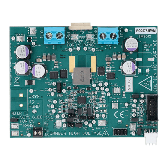
EVM User's Guide: BQ25758EVM, BQ25758AEVM
BQ25758 and BQ25758A Evaluation Modules
Description
The BQ25758 and BQ25758A evaluation modules
(EVM) are complete evaluation systems for the
BQ25758 and BQ25758A ICs. The BQ25758EVM and
the BQ25758AEVM have a max input and output of
55V and a max output current of 10A.
The BQ25758 and BQ25758A ICs are wide voltage,
bidirectional switched-mode buck-boost controllers.
These devices offer high-efficiency power conversion
over a wide voltage range with output CC-CV control.
These ICs have a wide input range of 4.2V to 60V and
a wide output range of up to 60V.
Get Started
1. Order the EVM on
ti.com
2. Order the
EV2400
to communicate with the EVM
3. Download the BQ25758 BQZ file
4. Download the BQ25758 EVM design files on
ti.com
SLUUCD0A – MARCH 2024 – REVISED AUGUST 2024
Submit Document Feedback
Features
•
Wide input voltage operating range: 4.2V to 55V
•
Wide output operating range: up to 55V
•
Synchronous buck-boost DC/DC controller with
NFET drivers
– Adjustable switching frequency from 200kHz to
– Optional synchronization to external clock
– Optional gate driver supply input for optimized
2
•
I
C-controlled or resistor programmable options
•
Power up from battery (reverse mode) output 4V to
55V
•
High safety integration
– Adjustable input overvoltage and undervoltage
– Output overvoltage and overcurrent protection
Copyright © 2024 Texas Instruments Incorporated
600kHz
efficiency
protection
BQ25758 and BQ25758A Evaluation Modules
Description
1
Advertisement
Table of Contents

Related Manuals for Texas Instruments BQ25758EVM


Summary of Contents for Texas Instruments BQ25758EVM
- Page 1 Wide input voltage operating range: 4.2V to 55V (EVM) are complete evaluation systems for the • Wide output operating range: up to 55V BQ25758 and BQ25758A ICs. The BQ25758EVM and • Synchronous buck-boost DC/DC controller with the BQ25758AEVM have a max input and output of NFET drivers 55V and a max output current of 10A.
-
Page 2: Kit Contents
1 Evaluation Module Overview 1.1 Introduction The BQ25758EVM and BQ25758AEVM can be evaluated for the full 240W range of USB Extended Power Range (EPR) in forward and reverse power direction. Typical applications include USB-PD extended power range applications, docking stations, monitors, and Portable Power Supplies. - Page 3 Evaluation Module Overview 1.4 General Texas Instruments High Voltage Evaluation (TI HV EMV) User Safety Guidelines WARNING Always follow TI's set-up and application instructions, including use of all interface components within their recommended electrical rated voltage and power limits. Always use electrical safety precautions to help verify your personal safety and those working around you.
- Page 4 The following warnings and cautions are noted for the safety of anyone using or working close to the BQ25758EVM or BQ25758AEVM. Observe all safety precautions. The BQ25758EVM and BQ25758AEVM circuit modules can become hot during operation due to the dissipation of heat. Avoid contact with the board. Follow all applicable safety procedures applicable to your laboratory.
- Page 5 The board has no fuse installed and relies on the external voltage source current limit to verify circuit protection. SLUUCD0A – MARCH 2024 – REVISED AUGUST 2024 BQ25758 and BQ25758A Evaluation Modules Submit Document Feedback Copyright © 2024 Texas Instruments Incorporated...
- Page 6 VOUT Default Output Voltage IAC Sense Resistor Input current sense resistor mΩ Table 2-2. PCB and Mechanical Parameters for the BQ25758EVM and the BQ25758AEVM Value Unit Board size (X dimension, or length) Board size (Y dimension, or width) IC + power stage max height...
-
Page 7: Recommended Operating Conditions
JP15 purpose indicator. JP16 Shunt JP16 to generate on board 3.3V pullup rail. Installed 2.3 Recommended Operating Conditions Table 2-5. Recommended Operating Conditions for BQ25758EVM and BQ25758AEVM Description UNIT VIN (J1) Input voltage to the EVM VOUT (J3) Output voltage of the EVM... - Page 8 Download and properly install bqStudio from https://www.ti.com/tool/BQSTUDIO. 2.5 Equipment Setup E-load VOUT IOUT Optional Gate EV2400 Drive Supply BQ25758 and BQ25758A Evaluation Modules SLUUCD0A – MARCH 2024 – REVISED AUGUST 2024 Submit Document Feedback Copyright © 2024 Texas Instruments Incorporated...
- Page 9 After selecting the target device, click Field View and then click the Read Register button. 10. Set WATCHDOG to disabled. SLUUCD0A – MARCH 2024 – REVISED AUGUST 2024 BQ25758 and BQ25758A Evaluation Modules Submit Document Feedback Copyright © 2024 Texas Instruments Incorporated...
- Page 10 V(J1(VAC)) = 20V ± 0.5V I(J1(IAC)) = 7.2A ± 0.5A V(J3(VOUT)) = 38V ± 0.5V I(J3(IOUT)) = 4A ± 0.5A BQ25758 and BQ25758A Evaluation Modules SLUUCD0A – MARCH 2024 – REVISED AUGUST 2024 Submit Document Feedback Copyright © 2024 Texas Instruments Incorporated...
- Page 11 Hardware Design Files 3 Hardware Design Files The following sections include the hardware design files for the BQ25758EVM and BQ25758AEVM. The sections include the schematics, board layouts, and Bill of Materials (BOM). 3.1 Schematics R1000 AC_OUT VSYS R1001 TP 45...
- Page 12 100nF D 100V 100k 100k 100V 1µF 100V PGND Figure 3-2. BQ25758 and BQ25758A EVM Schematic Page 2 BQ25758 and BQ25758A Evaluation Modules SLUUCD0A – MARCH 2024 – REVISED AUGUST 2024 Submit Document Feedback Copyright © 2024 Texas Instruments Incorporated...
- Page 13 3V3_PULLUP PGND PGND PGND PGND P GND PGND PGND Figure 3-3. BQ25758 and BQ25758A EVM Schematic Page 3 SLUUCD0A – MARCH 2024 – REVISED AUGUST 2024 BQ25758 and BQ25758A Evaluation Modules Submit Document Feedback Copyright © 2024 Texas Instruments Incorporated...
- Page 14 For BQ25756 variant, Install JP1, JP4, JP5, JP6, JP9, JP10, pin 1-2 of JP12, JP13, JP14, JP15, and JP16 Figure 3-4. BQ25758 and BQ25758A EVM Schematic Page 1. DNP means "Do Not Populate". BQ25758 and BQ25758A Evaluation Modules SLUUCD0A – MARCH 2024 – REVISED AUGUST 2024 Submit Document Feedback Copyright © 2024 Texas Instruments Incorporated...
-
Page 15: Pcb Layout
Hardware Design Files 3.2 PCB Layout Figure 3-5. Top Layer and Overlay Figure 3-6. Layer 2 -GND SLUUCD0A – MARCH 2024 – REVISED AUGUST 2024 BQ25758 and BQ25758A Evaluation Modules Submit Document Feedback Copyright © 2024 Texas Instruments Incorporated... - Page 16 Hardware Design Files www.ti.com Figure 3-7. Signal Layer 1 Figure 3-8. Signal Layer 2 BQ25758 and BQ25758A Evaluation Modules SLUUCD0A – MARCH 2024 – REVISED AUGUST 2024 Submit Document Feedback Copyright © 2024 Texas Instruments Incorporated...
- Page 17 Hardware Design Files Figure 3-9. Layer 5 - GND Figure 3-10. Bottom Layer SLUUCD0A – MARCH 2024 – REVISED AUGUST 2024 BQ25758 and BQ25758A Evaluation Modules Submit Document Feedback Copyright © 2024 Texas Instruments Incorporated...
- Page 18 DO-214AC DO-214AC (SMA) FID1, FID2, Fiducial mark. There is nothing to buy or FID3, FID4, mount. FID5, FID6 BQ25758 and BQ25758A Evaluation Modules SLUUCD0A – MARCH 2024 – REVISED AUGUST 2024 Submit Document Feedback Copyright © 2024 Texas Instruments Incorporated...
- Page 19 5 mOhms ±1% 5W Chip Resistor Wide 4320 WIDE_4320 (11050 Metric), 2043 Current Sense, Moisture Resistant Metal Foil SLUUCD0A – MARCH 2024 – REVISED AUGUST 2024 BQ25758 and BQ25758A Evaluation Modules Submit Document Feedback Copyright © 2024 Texas Instruments Incorporated...
- Page 20 Samtec Shunt, 100mil, Gold plated, Black Shunt JP2, SH-JP3, SH-JP4, SH- JP5, SH-JP6, SH-JP7, SH- JP8, SH-JP9, SH-JP10 BQ25758 and BQ25758A Evaluation Modules SLUUCD0A – MARCH 2024 – REVISED AUGUST 2024 Submit Document Feedback Copyright © 2024 Texas Instruments Incorporated...
- Page 21 Chemistry Battery Charge Controller LT3010EMS8E-PBF Analog Devices Linear Voltage Regulator IC Positive MSOP8 Adjustable 1 Output 50mA 8-MSOP-EP SLUUCD0A – MARCH 2024 – REVISED AUGUST 2024 BQ25758 and BQ25758A Evaluation Modules Submit Document Feedback Copyright © 2024 Texas Instruments Incorporated...
-
Page 22: Revision History
Changes from Revision * (March 2024) to Revision A (August 2024) Page • Updated document to include BQ25758AEVM....................BQ25758 and BQ25758A Evaluation Modules SLUUCD0A – MARCH 2024 – REVISED AUGUST 2024 Submit Document Feedback Copyright © 2024 Texas Instruments Incorporated... - Page 23 TI products. TI’s provision of these resources does not expand or otherwise alter TI’s applicable warranties or warranty disclaimers for TI products. TI objects to and rejects any additional or different terms you may have proposed. IMPORTANT NOTICE Mailing Address: Texas Instruments, Post Office Box 655303, Dallas, Texas 75265 Copyright © 2024, Texas Instruments Incorporated...
Need help?
Do you have a question about the BQ25758EVM and is the answer not in the manual?
Questions and answers