Sign In
Upload
Manuals
Brands
Allied Telesis Manuals
Switch
x240-10GHXm PoE++
Allied Telesis x240-10GHXm PoE++ Manuals
Manuals and User Guides for Allied Telesis x240-10GHXm PoE++. We have
1
Allied Telesis x240-10GHXm PoE++ manual available for free PDF download: Installation Manual
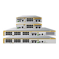
Allied Telesis x240-10GHXm PoE++ Installation Manual (132 pages)
MULTI-GIGABIT LAYER 2 SWITCHES
Brand:
Allied Telesis
| Category:
Switch
| Size: 7 MB
Table of Contents
Electrical Safety and Emissions Standards
3
Industry Canada
3
VCCI Statement
3
Regulatory Approvals
4
Environmental Compliance
5
Table of Contents
7
Preface
15
Document Conventions
16
Contacting Allied Telesis
17
Chapter 1: Overview
19
Front and Rear Panels
20
X240-10Ghxm Front Panel
20
X240-10Gtxm Front Panel
20
X240-26Ghxm Front Panel
20
Figure 1: Front Panel of the X240-10Ghxm Switch
20
Figure 2: Front Panel of the X240-10Gtxm Switch
20
Figure 3: Front Panel of the X240-26Ghxm Switch
20
X240-26Gtxm Front Panel
21
X240-10Ghxm Rear Panel
21
X240-10Gtxm Rear Panel
21
Figure 4: Front Panel of the X240-26Gtxm Switch
21
Figure 5: Rear Panel of the X240-10Ghxm Switch
21
Figure 6: Rear Panel of the X240-10Gtxm Switch
21
Rear Panel of X240-26Ghxm and X240-26Gtxm
22
Figure 7: Rear Panel of the X240-26Ghxm and X240-26Gtxm Switches
22
Management Panel
23
Figure 8: Management Panel
23
Features
24
X240 Models
24
10/100M/1/2.5/5G Copper Ports
24
Table 1: Basic Features
24
1/10G SFP+ Ports
25
Power over Ethernet
25
Leds
26
Installation Options
26
Management Software and Interfaces
26
Console Port
26
USB Port
27
Management Methods
27
MAC Address Table
27
Energy Savings
27
100M/1G/2.5G/5G Copper Ports
28
Connector Type
28
Speed
28
Duplex Mode
28
Maximum Distance
28
Cable Requirements
28
Automatic MDIX Detection
29
X240-10Ghxm and X240-26Ghxm Leds
29
Figure 9: Leds for the Copper Ports on the X240-10Ghxm and X240-26Ghxm Switches
29
Table 2: Leds for Poe Ports on the X240-10Ghxm and X240-26Ghxm
30
X240-10Gtxm and X240-26Gtxm Leds
31
Figure 10: Leds for the Copper Ports on the X240-10Gtxm and X240-26Gtxm Switches
31
Table 3: Leds for the Ports on the X240-10Gtxm and X240-26Gtxm
31
Power over Ethernet (Poe) on the X240-10Ghxm and X240-26Ghxm Switches
32
Poe Standards
32
Powered Device Classes
32
Power Budget
33
Table 4: IEEE Powered Device Classes
33
Table 5: Poe Requirements
33
Port Priorities
34
Wiring Implementation
34
Table 6: Poe Alternatives a and B for the Copper Ports
35
SFP+ Transceiver Ports
36
SFP+ Transceivers
36
Leds
36
Figure 11: SFP+ Transceiver Ports Leds
36
Table 7: LEDS for the SFP+ Transceiver Ports
36
Fault and Power Leds
37
Figure 12: Fault and Power Leds
37
Table 8: Fault and Power LEDS
37
Eco-Friendly Button
39
Figure 13: Eco-Friendly Button
39
USB Port
40
USB Port LED
40
Figure 14: USB Port LED
40
Table 9: USB Port LED
40
Console Port
41
Figure 15: VT-Kit3 Management Cable
41
Power Supply and Fan
43
Power Supply
43
Fan
43
Table 10: Fan in the X240 Series Switches
43
Chapter 2: Beginning the Installation
45
Reviewing Safety Precautions
46
Choosing a Site for the Switch
50
Unpacking the X240-10Ghxm or X240-10Gtxm Switch
51
Figure 16: Contents of the X240-10Ghxm and X240-10Gtxm Switches
51
Unpacking the X240-26Ghxm or X240-26Gtxm Switch
52
Figure 17: Contents of the X240-26Ghxm and X240-26Gtxm Switches
52
X240-10Ghxm and X240-10Gtxm Installation Options
53
Figure 18: Installation Options for the X240-10Ghxm and X240-10Gtxm Switches
53
X240-26Ghxm and X240-26Gtxm Installation Options
54
Figure 19: Installation Options for the X240-26Ghxm and X240-26Gtxm Switches
54
Accessory Hardware
55
Figure 20: BRKT-J24 Accessory Kit (Optional)
55
Figure 21: RKMT-J14 Accessory Kit (Optional)
55
Figure 22: RKMT-J15 Accessory Kit (Optional)
56
Recording the Serial Number and MAC Address
57
Figure 23: Serial Number and MAC Address Labels
57
Chapter 3: Installing the Switch on a Table or Desktop
59
Figure 24: Attaching the Bumper Feet
60
Chapter 4: Installing the Switch in an Equipment Rack
61
Overview of Installing the Switch in an Equipment Rack
62
X240-10Ghxm or X240-10Gtxm Switch
62
Figure 25: RKMT-J14 Brackets and for the X240-10Ghxm and X240-10Gtxm Switches
62
Figure 26: RKMT-J15 Bracket
62
X240-26Ghxm Switch
63
Figure 27: RKMT-J14 Bracket with Switches
63
Figure 28: BRKT-J24 Brackets and the X240-26Ghxm Switch
63
Installing the X240-10Ghxm and X240-10Gtxm Switches in an Equipment Rack with the RKMT-J14 Brackets
64
Required Items
64
Switch Orientations in the Equipment Rack
64
Figure 29: Bracket Holes
64
Figure 30: RKMT-J14 Bracket Holes
65
Figure 31: Switch Orientations with the Front Panel Facing the Front of the Equipment Rack
65
Installing the Switch
66
Figure 32: Switch Orientations with the Rear Panel Facing the Front of the Equipment Rack
66
Figure 33: Attaching the Handles to the RKMT-J14 Brackets
67
Figure 34: Attaching the RKMT-J14 Brackets to the X240-10Ghxm and X240-10Gtxm Switches I
67
Figure 35: Installing the X240-10Ghxm or X240-10Gtxm Switch in a Rack with the RKMT-J14 Brackets
68
Installing the X240-10Ghxm and X240-10Gtxm Switches in an Equipment Rack with the RKMT-J15 Bracket
69
Required Items
69
Installing the Switch
69
Figure 36: Installing the RKMT-J15 Bracket in the Equipment Rack
69
Figure 37: Loosening the Two Thumbscrews on the Front of the RKMT-J15 Bracket
70
Figure 38: Sliding out the Tray from the RKMT-J15 Bracket
70
Figure 39: Removing the Bumper Feet from the Bottom Panel of the Switch
71
Figure 40: Placing a Switch in the RKMT-J15 Bracket
72
Figure 41: Securing the Switch to the RKMT-J15 Bracket
72
Figure 42: Sliding in the RKMT-J15 Bracket Tray
73
Figure 43: Tightening the Two Thumbscrews on the RKMT-J15 Bracket
74
Installing the X240-26Ghxm or X240-26Gtxm Switch in an Equipment Rack
75
Required Items
75
Switch in the Equipment Rack
75
Figure 44: X240-26Ghxm Switch in an Equipment Rack
75
Installing the Switch
76
Figure 45: Attaching the Equipment Rack Brackets to the X240-26Ghxm Switch
76
Figure 46: Installing the X240-26Ghxm Switch in an Equipment Rack
77
Chapter 5: Installing the Switch on a Wall Using the BRKT-J24 Wall Mount Kit
79
Switch Orientations on a Wall
80
Figure 47: Positioning the X240 Series Switches on the Wall
80
Installation Guidelines
81
Tools and Material
81
Installing the Switch on a Wall Using the BRKT-J24 Brackets
82
Figure 48: Attaching the Wall Brackets to the Switch
83
Figure 49: Marking the Locations of the Bracket Keyholes on a Wall
84
Figure 50: Securing the Switch to the Wall Using the Keyhole
85
Figure 51: Securing the Chassis Using the Keyhole
86
Figure 52: Securing the Switch Using the Screw Holes
86
Figure 53: Wall Mounting of Switch, Brackets, and Screws (Top View)
87
Chapter 6: Cabling the Networking Ports
89
Cabling Copper Ports
90
Installing SFP and SFP+ Transceivers
92
Installing SFP and SFP+ Transceiver
93
Figure 54: Removing the Dust Plug from an SFP+ Port
93
Figure 55: Installing SFP+ Transceivers
93
Figure 56: Removing the Dust Cover from an SFP or SFP+ Transceiver
94
Figure 57: Positioning the SFP or SFP+ Handle in the Upright Position
94
Figure 58: Connecting a Fiber Optic Cable to an SFP or SFP+ Transceiver
95
Installing SP10TW Direct Connect Cables
96
Installing SP10TW Direct Connect Cable
96
Figure 59: Installing SP10TW Cables
96
Chapter 7: Powering on the Switch
99
Powering on the Switch
100
Figure 60: Installing the Power Cord Retaining Clip
100
Figure 61: Connecting the AC Power Cord
101
Figure 62: Lowering the Power Cord Retaining Clip
101
Figure 63: Connecting the Power Cord to an AC Power Source
102
Chapter 8: Managing the Switch
103
Starting a Management Session
104
Through the Console Port
104
Figure 64: VT-Kit3 Management Cable with Workstation and Switch
105
With a DHCP Server
106
With the Default Ipv4 Address
107
Verifying the Switch
109
Specifying Ports in the Command Line Interface
110
Figure 65: PORT Parameter in the Command Line Interface
110
Table 11: PORT Parameter Format
110
Chapter 9: Management Stacking
111
Overview
112
Command Node
112
Node
112
Management Stack
112
Setting up a Management Stack
113
Step 1: Configuring the Command Node
113
Figure 66: Management Stack of Nodes
113
Step 2: Configuring Node-01
114
Step 3: Configuring Node-02
115
Checking the Status of the Stack
116
Table 12: Fields in the Output of the 'Show Mstack Node' Command
116
Running Commands on Devices in the Management Stack
117
Copying Files between Management Stack Members
118
Using Remote Login to Copy Files between Other Units in the Management Stack
118
Chapter 10: Troubleshooting
119
Appendix A: Technical Specifications
123
Physical Specifications
124
Figure 67: X240-10Ghxm Switch Dimensions
124
Table 13: Product Dimensions (Wxdxh)
124
Figure 68: X240-10Gtxm Switch Dimensions
125
Figure 69: X240-26Ghxm and X240-26Gtxm Switch Dimensions
125
Table 14: Product Weights
125
Table 15: Ventilation Requirements
126
Environmental Specifications
127
Table 16: Environmental Specifications
127
Power Specifications
128
Table 17: Maximum Power Consumptions
128
Table 18: Input Voltages
128
Table 19: Heat Dissipations
128
Copper Port Pinouts
129
Figure 70: Pin Layout for the RJ-45 Copper Ports (Front View)
129
Table 20: Pin Signals on the RJ-45 Copper Ports at 10 or 100Mbps
129
Table 21: Pin Signals on the RJ-45 Copper Ports at 1/2.5/5G
130
Style Serial Console Port Pinouts
131
Table 22: Pin Signals of the RJ-45 Style Serial Console Port
131
Console Management Cable with DB-9 Female and RJ-45 Connectors
132
Figure 71: Console Port Management Cable with DB-9 Female and RJ-45 Connectors
132
Table 23: Pin-Outs of Console Port Management Cable with DB-9 Female and RJ-45 Connectors
132
Advertisement
Advertisement
Related Products
Allied Telesis x240-10GTXm
Allied Telesis x230-10GP
Allied Telesis x230-28GP
Allied Telesis x230-10GT
Allied Telesis x230-18GP
Allied Telesis x230-18GT
Allied Telesis x230-28GT
Allied Telesis x240 Series
Allied Telesis x240-26GHXm PoE++
Allied Telesis x240-26GTXm
Allied Telesis Categories
Switch
Network Router
Media Converter
Network Hardware
Wireless Access Point
More Allied Telesis Manuals
Login
Sign In
OR
Sign in with Facebook
Sign in with Google
Upload manual
Upload from disk
Upload from URL