
Related Manuals for GW Instek AFG-4000 Series


Summary of Contents for GW Instek AFG-4000 Series
- Page 1 Arbitrary Function Generator AFG-4000 Series User Manual ISO-9001 CERTIFIED MANUFACTURER...
- Page 2 This manual contains proprietary information, which is protected by copyright. All rights are reserved. No part of this manual may be photocopied, reproduced or translated to another language without prior written consent of Good Will company. The information in this manual was correct at the time of printing. However, Good Will continues to improve products and reserves the rights to change specification, equipment, and maintenance procedures at any time without notice.
-
Page 3: Table Of Contents
Table of Contents Table of Contents SAFETY INSTRUCTIONS ........... 4 Safety Precaution before Operation ......8 Electro-static Discharge (ESD) Protection ....11 First Time to Power on ..........12 GETTING STARTED ............13 Main Features ............16 Appearance ............... 18 Boot Up .............. -
Page 4: Safety Instructions
AFG-4000 User Manual AFETY INSTRUCTIONS This chapter contains important safety instructions that you must follow during operation and storage. Read the following before any operation to insure your safety and to keep the instrument in the best possible condition. Safety Symbols These safety symbols may appear in this manual or on the instrument. -
Page 5: Safety Guidelines
SAFETY INSTRUCTIONS Do not dispose electronic equipment as unsorted municipal waste. Please use a separate collection facility or contact the supplier from which this instrument was purchased. Safety Guidelines Do not place any heavy object on the AFG-4000. General Guideline Avoid severe impact or rough handling that ... - Page 6 AFG-4000 User Manual Fuse type: F2A/250V. Fuse Only qualified technicians should replace the fuse. WARNING To ensure fire protection, replace the fuse only with the specified type and rating. Disconnect the power cord and all test leads ...
- Page 7 SAFETY INSTRUCTIONS (Pollution Degree) EN 61010-1 specify the pollution degrees and their requirements as follows. The AFG-4000 falls under degree 2. Pollution refers to “addition of foreign matter, solid, liquid, or gaseous (ionized gases), that may produce a reduction of dielectric strength or surface resistivity”.
-
Page 8: Power Cord For The United Kingdom
AFG-4000 User Manual Power cord for the United Kingdom When using the function generator in the United Kingdom, make sure the power cord meets the following safety instructions. NOTE: This lead/appliance must only be wired by competent persons WARNING: THIS APPLIANCE MUST BE EARTHED IMPORTANT: The wires in this lead are coloured in accordance with the following code: Green/ Yellow:... -
Page 9: Safety Precaution Before Operation
SAFETY INSTRUCTIONS Safety Precaution before Operation Check Power Supply The analyzer is equipped with a three-wire power cord in accordance with international safety standards. The product must be grounded properly before being powered on, as floating or improper ground may cause damage to the instrument or personal injury. - Page 10 AFG-4000 User Manual Improper grounding may cause damage to the WARNING instrument, or result in personal injury. Make sure the grounding conductor of the function generator is grounded before turning on the instrument. Always use a well-grounded power source. Do not use an external power cable, power cord or an auto transformer without grounded protection.
-
Page 11: Electro-Static Discharge (Esd) Protection
SAFETY INSTRUCTIONS Electro-static Discharge (ESD) Protection ESD is an issue often ignored by users. Damage from ESD on the instrument is unlikely to occur immediately but will significantly reduce the reliability of it. Therefore, ESD precautions should be implemented in the work environment, and applied daily. Generally, there are two steps to manage ESD protection: 1. -
Page 12: First Time To Power On
AFG-4000 User Manual First Time to Power on Connect the three-pin AC power cord into the instrument. Insert the plug into a power socket provided with a protective ground. Check the power source before turning on the function WARNING generator, to protect the device from damage. 1. -
Page 13: Getting Started
GETTING STARTED ETTING STARTED This chapter introduces the front / rear panel, the user interface and explains how to use the instrument with a measurement example demonstration. Main Features ............16 Appearance ............... 18 AFG-4125E Front Panel ............18 AFG-4125AE Front Panel ............. 18 AFG-4225E/4235/4260/4280/4210H/4225H Front Panel .. - Page 14 AFG-4000 User Manual Set the sampling rate ............... 39 Set the display function for arbitrary wave ......39 Set the editing function for arbitrary wave ......40 Set the built-in waveforms for arbitrary wave ......41 Set the Save function for arbitrary wave ......... 42 Set the Import function for arbitrary wave ......
- Page 15 GETTING STARTED Oscillation Shift Keying (OSK) ..........62 Setting procedure for OSK ............63 SUM Modulation (SUM) ............63 Setting procedure for SUM ............64 Sweep Frequency Output ............ 65 Setting procedure for the sweep mode: ........65 Burst Waveform Output ............67 Set the Burst for N cycles .............
-
Page 16: Main Features
AFG-4000 User Manual Main Features Provide single-channel or dual-channel output - AFG-4125E/ 4125AE: single channel - AFG-4225E/ 4235/ 4260/ 4280/ 4210H/ 4225H: dual-channel Built-in Sine, Square, Triangle, Ramp, Pulse, Noise, Harmonic wave, Arbitrary wave Min. resolution is 1uHz ... - Page 17 GETTING STARTED - AFG-4125E/ 4125AE/ 4225E provide USB interface 8” TFT LCD Display, 800*480 resolution - Multi-Touch Display: AFG-4235/ 4260/ 4280/ 4210H/ 4225H Without Touch Display: AFG-4125E/ 4125AE/ 4225E...
-
Page 18: Appearance
AFG-4000 User Manual Appearance AFG-4125E Front Panel AFG-4125AE Front Panel ⑰ ⑯... -
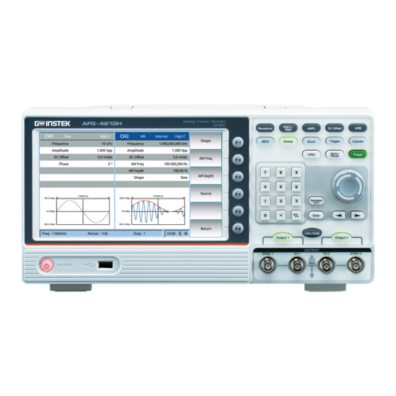
Page 19: Afg-4225E/4235/4260/4280/4210H/4225H Front Panel
GETTING STARTED AFG-4225E/4235/4260/4280/4210H/4225H Front Panel ① ② ③ ④ ⑤ ⑥ ⑬ ⑫ ⑪ ⑩ ⑨ ⑧ ⑦ ⑮ ⑭ Display the user interface. 1. LCD The F1 to F6 function keys directly 2. Menu soft correspond to the soft keys on the right- keys hand side of display. - Page 20 AFG-4000 User Manual Output modulation waveform; Sweep sine, square, Sweep triangle or arbitrary waves; Generate pulse trains of Burst sine waves, square waves, triangle waves, pulse waves, noise waves or arbitrary waves; Manual trigger button; Trigger Frequency counter button; Counter Auxiliary function button;...
- Page 21 GETTING STARTED When Utility → CH1/2 Settings → 7. CH2 Synchronou CH2 Synchronization is set to On, this s output terminal outputs a synchronization terminal signal that matches the current configuration of CH2. Turn on or off the output of CH2 8.
-
Page 22: Afg-4125E/4125Ae/4225E Rear Panel
AFG-4000 User Manual Power Power Amplifier input port Amplifier AFG-4125E/4125AE/4225E Rear Panel AFG-4235/4260/4280/4210H/4225H Rear Panel ① ② ⑩ ⑨ ③ ④ ⑤ ⑧ ⑦ ⑥... - Page 23 GETTING STARTED 1. Handle 2. Heat sink fan Power input: 100-240V± 10% AC 3. AC Power Input Socket 50-60Hz. F2A/250V 4. Fuse box To adjust the angle of the device. 5. Stool LAN interface for remote control. 6. LAN Port USB type-B device port is used to 7.
- Page 24 AFG-4000 User Manual When modulating waveform, output 10. Mod/FSK/Trig scanning frequency, or output pulse Connector train, the signal connected here can be used as an external signal source. Note: If one channel turns on AM, FM, PM, PWM or OSK, and another channel turns on ASK, FSK, PSK, frequency sweep or pulse train, and both channels are set to external...
-
Page 25: Boot Up
GETTING STARTED Boot Up Before turning on the power, confirm that the Confirm AC voltage input power meets the conditions of 100-240 V (±10%), 50/60 Hz. The fuse is a 250 V, F2AL slow-blow type, and Connect the AC connects the AC power cord to the rear panel power cord receptacle. -
Page 26: User Interface
AFG-4000 User Manual User Interface NO Description Display areas of CH1 and CH2. Indicate Channel Status whether the corresponding channel is selected and turned on (ON/OFF).The area of the channel currently selected is highlighted and the on/off state of the channel currently turned on is "ON". - Page 27 GETTING STARTED Display the operation menu corresponding to Menu the function currently selected. For example, the "Sine" function menu is displayed in the above figure. When the instrument is correctly connected to LAN status light the LAN, this indicator will light. When the generator detects a USB storage USB status light device, this indicator will light.
- Page 28 AFG-4000 User Manual Display the current waveform DC offset in Offset each channel. Press the corresponding softkey Offset and use the numeric keyboard or direction keys and knob to modify this parameter. The parameter that can be modified currently will be highlighted and the lightspot above the number indicates current cursor location.
-
Page 29: Product Operation
GETTING STARTED Product Operation The operating methods of AFG-4000 are provided in the present section as a quick start guide for users. For its program control, factory default settings and other details, refer to other sections of this manual. Channel Settings Select a channel for configuration: Select a channel for configuration before configuring waveform parameters. -
Page 30: Sine Wave Output
AFG-4000 User Manual Sine Wave Output After you successively press Waveform and F1, the user interface (UI) for sine wave will appear. You can click the “Menu” button on the operation panel or directly click the corresponding menu box on the screen to set the output waveform parameters for sine wave. The sine wave menu contains: frequency, amplitude, offset, and phase. -
Page 31: Set The Amplitude
GETTING STARTED Backspace. You can confirm the default unit already input by pressing Enter. You can also press a soft key MHz, kHz, Hz, mHz, or uHz to select the unit of parameter. After you directly click the Frequency on the ... -
Page 32: Square Wave Output
AFG-4000 User Manual the desired value. After you press F3, you can set the phase to 0° via this shortcut button. Square Wave Output After you successively press Waveform and F2, the UI for square wave will appear. You can click the “Menu” button on the operation panel or directly click the corresponding menu box on the screen to set the output waveform parameters for square wave. -
Page 33: Set The Symmetry
GETTING STARTED UI for Triangle Wave Glossary Symmetry: It is used to set the percentage of cycles when triangle wave is rising. Set the symmetry 1. Use the knob to directly change the value Steps within Parameter 5 in the UI for Triangle Wave;... -
Page 34: Pulse Wave Output
AFG-4000 User Manual Symmetry Setting for Triangle Wave Pulse Wave Output After you successively press Waveform and F4, the UI for pulse wave will appear. You can click the “Menu” button on the operation panel or directly click the corresponding menu box on the screen to set the output waveform parameters for pulse wave. - Page 35 GETTING STARTED Glossary PW is the abbreviation of pulse width, which consists of positive PW and negative PW. A positive PW is defined as the time from the middle threshold (50%) of the rising edge to the middle threshold (50%) of the next falling edge.
-
Page 36: Set The Pulse Width
AFG-4000 User Manual The setting range of PW is subject to the “minimum pulse width” and the “pulse period.” PW ≥ minimum pulse width PW ≤ pulse period - minimum pulse width Pulse duty cycle is defined as the percentage of a PW in the ... -
Page 37: Set The Rise Time
GETTING STARTED default input by pressing the soft key Enter; or you can directly click the Duty Cycle on the screen, and a numeric input field will pop up. Just continue to enter the desired value. You can delete the last digit by pressing the soft key ←. -
Page 38: Noise Wave Output
AFG-4000 User Manual value. Next, select the desired unit from the menu on the right side. You can enter the desired value by clicking the desired unit (ks, s, ms, us, ns) or pressing Enter. You can delete the last digit by pressing the soft key Backspace. -
Page 39: Set The Sampling Rate
GETTING STARTED The arbitrary wave menu contains: frequency, amplitude, offset, phase and sampling rate. Please refer to the “Sine Wave Output“ section for the settings of frequency, amplitude and offset. UI for Arbitrary Wave Set the sampling rate Press FREQ/Rate. When the menu item “Sampling Rate” is displayed in red, you can use the knob, numeric keypad or touch screen within Parameter 4 in the UI for Arbitrary Wave to set the desired value. -
Page 40: Set The Editing Function For Arbitrary Wave
AFG-4000 User Manual center of the waveform to be displayed as needed. Click “OK” to save the settings. Click “Back” to return to the previous menu. Click Zoom In or Zoom Out to enlarge or shrink the displayed waveform. 4. Press F3 to move the display window forwards. -
Page 41: Set The Built-In Waveforms For Arbitrary Wave
GETTING STARTED 4. Press F4 to enter the Clear function menu. Set the Start and Length for clearing as needed. Click “Done” to save the settings. Click “Complete” to clear the waveform address already set. Successively click “All” and “Complete” to clear the addresses of all waveforms. -
Page 42: Set The Save Function For Arbitrary Wave
AFG-4000 User Manual Turn the knob or directly click the pop-up window on the screen to select the desired waveform (such as Airy). Press the knob or F1 to output the Airy Function. Set the Save function for arbitrary wave By using the Save function, the user can save the waveform in the memory or USB as needed. -
Page 43: Set The Output Function For Arbitrary Wave
GETTING STARTED By using the Import function, the user can select and recall the waveforms stored in the memory or USB. The operation procedure is stated below: 1. Successively press ARB and F5 to enter the Steps Import function menu. 2. -
Page 44: Harmonic Wave Output
AFG-4000 User Manual clear the data for which “Enter” is not clicked and then return to the previous set value. 4. Press F6 to return to the previous menu. Harmonic Wave Output After you successively press Waveform and F6, the UI for harmonic wave will appear. -
Page 45: Select The Harmonic Wave Type
GETTING STARTED UI for Harmonic Wave This signal source can output up to 16 harmonic orders. After selecting CH1 or CH2, press F6 on the front panel to enter the Harmonic Wave Settings menu. You can set the parameters of the fundamental harmonic, select the type of the harmonic wave to be output and specify its highest harmonic order as well as the amplitude and phase of individual harmonic waves. -
Page 46: Customize
AFG-4000 User Manual Press F1 to enter the menu and select the option “harmonic wave type.” Next, press F3 and the instrument will output the fundamental harmonic and harmonic waves in sequence. Customize Press F1 to enter the menu and select the option “harmonic wave type.”... -
Page 47: Set The Harmonic Amplitude
GETTING STARTED Set the harmonic amplitude Press F4 to set the parameter value of the harmonic amplitude. Such parameter item is displayed in red. Within Parameter 6 in the UI for Harmonic Wave, use the knob or numeric keypad, or directly click the Harmonic Amplitude on the screen. -
Page 48: Setting Procedure For Am
AFG-4000 User Manual UI for Amplitude Modulation (AM) Setting procedure for AM 1. Successively press the function key MOD and Steps F1 to select AM as modulation type. 2. Press Waveform and the waveform and parameters of the current carrier will be displayed. -
Page 49: Double Side Band Amplitude Modulation (Dsbam)
GETTING STARTED Glossary AM Frequency: the frequency of modulation waveform; Modulation Depth: the amplitude variation range of the output modulation waveform. During modulation at 0%, the output amplitude will be half of the amplitude setpoint. During modulation at 100%, the output amplitude will be equal to the amplitude setpoint. -
Page 50: Frequency Modulation (Fm)
AFG-4000 User Manual displayed. You can change the carrier parameters. Refer to “Sine Wave Output“ for more details. Press MOD again to go back to the Modulation Mode screen. 3. Press F4 to select a signal source. If you select “External”, the setting procedure will be completed after the external signal source is connected to the Ext Mod In interface on the... -
Page 51: Phase Modulation (Pm)
GETTING STARTED 1. Successively press the function key MOD and Steps F3 to select FM as modulation type. 2. Press Waveform and the waveform and parameters of the current carrier will be displayed. You can change the carrier parameters. Refer to “Sine Wave Output“ for more details. -
Page 52: Setting Procedure For Pm
AFG-4000 User Manual UI for Phase Modulation (PM) Setting procedure for PM 1. Successively press the function key MOD and Steps F4 to select PM as modulation type. 2. Press Waveform and the waveform and parameters of the current carrier will be displayed. -
Page 53: Pulse Width Modulation (Pwm)
GETTING STARTED Pulse Width Modulation (PWM) The output modulation waveform consists of carrier and modulating wave. The PWM function is valid for modulation of pulse waves only. Consequently, carriers can only be pulse waves. In a PWM process, the pulse width of a carrier (pulse wave) varies with the transient voltage of the modulation waveform. -
Page 54: Amplitude Shift Keying (Ask)
AFG-4000 User Manual 6. Press F2 to set the PWM rate within the range of 2 mHz to 1 MHz (only for internal signal sources). 7. Press F3 to set the deviation (in case of a non- modulation mode, the setting on the Pulse Wave menu is pulse width or PWM duty). -
Page 55: Phase Shift Keying (Psk)
GETTING STARTED 1. Successively press the function key MOD, F6 Steps and F1 to select ASK as modulation type. Select a carrier waveform as needed. Take sine wave as an example. 2. Press Waveform and the waveform and parameters of the current carrier will be displayed. -
Page 56: Setting Procedure For Psk
AFG-4000 User Manual varies with the transient voltage of the modulation waveform. The UI for PSK is illustrated below. UI for Phase Shift Keying (PSK) Setting procedure for PSK 1. Successively press the function key MOD, F6 Steps and F2 to select PSK as modulation type. Select a carrier waveform as needed. -
Page 57: Frequency Shift Keying (Fsk)
GETTING STARTED If you select “External” as signal source, set the slope to “Positive”. As a result, when a low logic level is Note input, the carrier phase will be output; when a high logic level is input, the modulation phase will be output. -
Page 58: Ternary Frequency Shift Keying (3Fsk)
AFG-4000 User Manual and F3 to select FSK as modulation type. Select a carrier waveform as needed. Take sine wave as an example. 2. Press Waveform and the waveform and parameters of the current carrier will be displayed. You can change the carrier parameters. -
Page 59: Setting Procedure For 3Fsk
GETTING STARTED UI for Ternary Frequency Shift Keying (3FSK) Setting procedure for 3FSK 1. Successively press the function key MOD, F6 Steps and F4 to select 3FSK as modulation type. Select a carrier waveform as needed. Take sine wave as an example. 2. -
Page 60: Setting Procedure For 4Fsk
AFG-4000 User Manual UI for Quaternary Frequency Shift Keying (4FSK) Setting procedure for 4FSK 1. Successively press the function key MOD, F6, Steps F5 and then F1 to select 4FSK as modulation type. Select a carrier waveform as needed. Take sine wave as an example. 2. -
Page 61: Setting Procedure For Bpsk
GETTING STARTED UI for Binary Phase Shift Keying (BPSK) Setting procedure for BPSK 1. Successively press the function key MOD, F6, Steps F5 and then F2 to select BPSK as modulation type. Select a carrier waveform as needed. Take sine wave as an example. 2. -
Page 62: Setting Procedure For Qpsk
AFG-4000 User Manual source). A carrier may be a sine wave, square wave, triangle wave, or arbitrary wave. The UI for QPSK is illustrated below. UI for Quadrature Phase Shift Keying (QPSK) Setting procedure for QPSK 1. Successively press the function key MOD, F6, Steps F5 and then F3 to select QPSK as modulation type. -
Page 63: Setting Procedure For Osk
GETTING STARTED UI for Oscillation Shift Keying (OSK) Setting procedure for OSK 1. Successively press the function key MOD, F6, Steps F5 and then F4 to select OSK as modulation type. Select a carrier waveform as needed. Take sine wave as an example. 2. -
Page 64: Setting Procedure For Sum
AFG-4000 User Manual UI for SUM Modulation (SUM) Setting procedure for SUM 1. Successively press the function key MOD, F6, Steps F5 and then F5 again to select SUM as modulation type. Select a carrier waveform as needed. Take sine wave as an example. 2. -
Page 65: Sweep Frequency Output
GETTING STARTED Sweep Frequency Output In the sweep mode, the frequency output will vary with the sweep type from the start frequency to the stop frequency within the specified sweep time. Only sine waves, square waves, triangle waves or arbitrary waves can be used to generate sweep signals. UI for Sweep Mode Setting procedure for the sweep mode:... - Page 66 AFG-4000 User Manual logarithmic changes. If Stepping is selected, you are free to a step count. 5. Press F2 to set a Start Frequency value. Refer to Table 1 for details. 6. Press F3 to set a Stop Frequency value. Refer to Table 1 for details.
-
Page 67: Burst Waveform Output
GETTING STARTED 1. Successively press F6 and F2 to select a trigger Steps source. “Internal” means that an internal signal source will be used. “External” means that an external signal source which uses the Mod/FSK/Trig interface on the rear panel will be used. -
Page 68: Set The Burst For N Cycles
AFG-4000 User Manual Set the Burst for N cycles UI for the Burst for N Cycles 1. In the UI for sine wave, square wave, triangle Steps wave, pulse wave, noise wave or arbitrary wave, after the function key Burst is pressed, bursts will be generated. -
Page 69: Set The Burst For Gating
GETTING STARTED 1,000,000 cycles. If you choose “Unlimited”, a continuous waveform will be output until a trigger event is received. In the Burst mode, the upper limit of the carrier frequency will be half of the original maximum carrier Note frequency. - Page 70 AFG-4000 User Manual UI for the Burst for Gating 1. In the UI for sine wave, square wave, triangle Steps wave, pulse wave or arbitrary wave, press the function key Burst. 2. You can select waveform functions by pressing Waveform. For instance, if you select “Sine” (sine wave), the waveform and parameters can be displayed after you press Waveform, and then you can change parameters.
-
Page 71: Frequency Counter
GETTING STARTED Frequency Counter The frequency counter is designed to measure the signals within the frequency range of 100 mHz to 200 MHz. The [10MHz In/Out/Counter] connector on the rear panel is used to receive signals from the frequency counter by default. The frequency counter will keep operating after startup, until the connector is set to the external clock input or clock output. -
Page 72: Utility Settings
AFG-4000 User Manual want to measure high-frequency signals with the frequency larger than 1 kHz, switch off HF rejection. Press F4 to select “Trigger Level”. Turn the knob to change the current digit indicated by the cursor. Move the cursor side to side by pressing the direction keys;... -
Page 73: Screen Saver
GETTING STARTED keypad to enter the brightness value (%). The brightness range is 0% to 100%. Screen Saver If there is no action within the preset screen saver time, the screen will enter the screen saver mode (the screen will deactivate, i.e., “Blank Screen”). -
Page 74: Ch1/Ch2 Settings
AFG-4000 User Manual CH1/CH2 Settings 1. Press the function key Utility. Press F2 to Steps select “CH1/CH2 Settings”. 2. Press F1 to select “CH1 Synchronization”. Press F1 to enable synchronization. Press F2 to disable synchronization. 3. Press F2 to select “CH2 Synchronization”. Press F1 to enable synchronization. -
Page 75: System Settings
GETTING STARTED on the screen cannot be modified. After the user defines the network parameter settings of the signal generator such as IP address, the user has to wait for more than 2s and reboot the machine in order to make them effective. Press F1 to select the “IP Address”. -
Page 76: Beeper
AFG-4000 User Manual Beeper Press the function key Utility. Press F5 to select “System Settings”. Press F2 to switch ON or OFF the beeper. Clock Reference The internal clock reference is available. An external clock reference from [10MHz In/ Out/ Counter] on the rear panel is also acceptable. Moreover, a clock reference can be output by the [Ref Clk Out] connector for the use by other devices. -
Page 77: Upgrade
GETTING STARTED Upgrade Press the function key Utility. Press F5 to select “System”. Insert the USB storage device to the USB connector on the front panel of the instrument. If no USB storage device is inserted, the “Firmware Upgrade” menu will be disabled. Note Press F5 to select “More”. -
Page 78: Operation Procedure
AFG-4000 User Manual extension “CFG”. You can restore the settings already stored from the files in the internal memory or USB storage device. Operation Procedure Press the function key Save/Recall on the front panel to enter the Save/Recall menu. Press F1 to enter the setup interface. If you want to store the settings in the internal ... -
Page 79: Set To The Factory Defaults (Preset)
GETTING STARTED Save/Recall menu. Press F2 to recall the arbitrary wave. If you want to recall any arbitrary wave stored in the USB storage device, just press F1 to choose “Media” and then press F2 to choose “USB Device”. Press F6 to go back to the main Save/Recall menu. - Page 80 AFG-4000 User Manual Harmonic order number Harmonic amplitude 1.000 Vpp Harmonic phase 0deg Modulation waveform Factory defaults Modulation type Modulation waveform Sine wave AM frequency 100.000 000 000 Hz Modulation depth 100.00% Signal source Internal Modulation frequency 100.000 000 000 Hz Frequency shift 100.000 000 Hz PM frequency...
- Page 81 GETTING STARTED Trigger source Internal Slope Positive Burst Factory defaults Trigger interval 1.000 000 000 s Burst mode N cycles Cycle number Trigger source Internal Slope Positive Polarity Positive Frequency counter Factory defaults Coupling Sensitivity HF rejection Trigger level 0 mV Utility Factory defaults Backlight...
-
Page 82: Channel (Ch1/Ch2) Function Settings
AFG-4000 User Manual Channel (CH1/CH2) Function Settings Set the load value For each output terminal of two channels on the front panel, the signal generator provides a 50 Ω constant output impedance in series. If the actual load impedance differs from the specified value, neither the amplitude nor the level for shift displayed will match the voltage level of the unit under test (UUT). - Page 83 GETTING STARTED 1. Synchronous switching Steps Enable or disable the synchronization signals from the [Sync Int] connector. Press Utility to set “CH1 Synchronization/CH2 Synchronization”. Choose to switch “ON” or “OFF” the the synchronization signal output. It remains “OFF” by default. Synchronization signals will be sent to the [Sync Int] connector.
- Page 84 AFG-4000 User Manual modulation frequency during internal modulation and are square waves with the duty cycle of 50%. In the first half period of the modulation waveform, synchronization signals will be high levels of the TTL. During external modulation, no synchronization signal will be output.
-
Page 85: Remote Control
GETTING STARTED Remote Control Establishing a Remote Connection This instrument supports communication with PC via a USB interface or LAN interface. With the host computer software “Waveform Editor” installed on the PC, you can perform various actions of the signal generator on the PC to control its output. The following sections describe how to connect the signal generator to the PC. -
Page 86: Using The Lan Interface
AFG-4000 User Manual Select “Port Settings”. In the settings dialog, select “USB” as communication port. After successful connection, the connection status indication in the lower right corner of the software screen will turn green. Using the LAN Interface Direct connection 1. -
Page 87: Connection Via A Router
GETTING STARTED to an IP address of which the first three digits are the same as, but the last digit is different from the IP address for PC networking as described in Step (2). In this example, “IP” is set to “192.168.1.99”. “Port” can be set to any value within the range of 0 to 4000. - Page 88 AFG-4000 User Manual Therefore, you have to specify the IP address. The default settings of the gateway and netmask should be consistent with the router settings. If the IP address is set to 192.168.1.101 and the netmask is set to 255.255.255.0, the gateway should be set to 192.168.1.1 by default.
- Page 89 GETTING STARTED successful connection. For the specific operation method of the Waveform Editor software, please directly press F1 to view the built-in help file.
-
Page 90: Specifications
AFG-4000 User Manual PECIFICATIONS Specifications This chapter lists the technical specifications and general technical specifications of the function generator. Unless otherwise stated, the technical specifications apply to the following conditions: The instrument has been preheated for 60 minutes before use. The instrument is in the calibration cycle and ... - Page 91 SPECIFICATIONS Arbitrary Arbitrary Built-in Function AFG-4125E AFG-4125AE 125 MSa/s Sampling rate AFG-4225E (user-editable AFG-4235 sampling rate range from AFG-4260 500 MSa/s 2μSa/s to AFG-4280 62.5MSa/s) AFG-4210H AFG-4225H 1.25 GSa/s AFG-4125E AFG-4125AE 15 MHz AFG-4225E AFG-4235 Repetition Rate AFG-4260 AFG-4280 30 MHz AFG-4210H AFG-4225H AFG-4125E...
- Page 92 AFG-4000 User Manual AFG-4125E AFG-4125AE <10 ns AFG-4225E AFG-4235 Minimum rise AFG-4260 and fall time AFG-4280 <3 ns AFG-4210H AFG-4225H AFG-4125E AFG-4125AE 8 ns AFG-4225E AFG-4235 Jitter AFG-4260 AFG-4280 3 ns AFG-4210H AFG-4225H Non-volatile 32 MB memory AFG-4125E 2 to 16384 points AFG-4125AE AFG-4225E AFG-4235...
- Page 93 SPECIFICATIONS Frequency characteristics Frequency resolution: 1 μHz or 10 significant figures; Frequency error: ± 1 ppm; Frequency aging rate: ± 1 ppm per year. AFG-4125E AFG-4125AE 25 MHz AFG-4225E AFG-4235 35 MHz Sine AFG-4260 60 MHz AFG-4280 80 MHz AFG-4210H 100 MHz AFG-4225H 250 MHz...
- Page 94 AFG-4000 User Manual AFG-4125AE AFG-4225E AFG-4235 35 MHz BW AFG-4260 60 MHz BW AFG-4280 80 MHz BW AFG-4210H 100 MHz BW AFG-4225H 120 MHz BW AFG-4125E AFG-4125AE 12.5 MHz AFG-4225E AFG-4235 17.5 MHz Harmonic AFG-4260 30 MHz AFG-4280 40 MHz AFG-4210H 50 MHz AFG-4225H...
- Page 95 SPECIFICATIONS 1mVpp to 5Vpp (≤80MHz, into 50Ω. 2mVpp to 10 Vpp open-circuit) 1mVpp to 2.5Vpp (≤120MHz, into 50Ω. 2mVpp to 5 Vpp open-circuit) 1mVpp to 1Vpp (≤250MHz, into 50Ω. 2mVpp to 2 Vpp open-circuit) AFG-4125E AFG-4125AE ≤10MHz: ±0.2dB AFG-4225E ≤60MHz: ±0.3dB AFG-4235 ≤100MHz: ±0.5dB (relative to 100 kHz Sine...
- Page 96 AFG-4000 User Manual protection ± (10 Vpk – Amplitude Vpp/ 2), (High resistance) DC offset range AFG-4125E ± (3 % of |setting| + 5 mV + AFG-4125AE amplitude Vpp * 0.5%) AFG-4225E AFG-4235 DC offset AFG-4260 accuracy (1 % of |setting| + 5 mV + AFG-4280 amplitude Vpp * 0.5%) AFG-4210H...
- Page 97 SPECIFICATIONS distortion ≤25MHz: <-45dBc AFG-4125AE AFG-4225E AFG-4235 Typical (0dBm) AFG-4260 ≤10MHz: <-70dBc AFG-4280 >10MHz: <-70dBc + 6dB/ AFG-4210H octave AFG-4225H Typical (0dBm, 10kHz offset) Phase noise 10MHz: ≤-110dBc/Hz Square AFG-4125E AFG-4125AE <30ns AFG-4225E AFG-4235 Rise/Fall time AFG-4260 <8ns AFG-4280 AFG-4210H AFG-4225H <5ns AFG-4125E...
- Page 98 AFG-4000 User Manual Triangle < 0.1% of peak output (Typical 1 kHz, 1 Vpp, 50% Linearity symmetry) 0.0% to 100.0% Symmetry...
- Page 99 SPECIFICATIONS Pulse AFG-4125E AFG-4125AE 200 ns to 1000 ks AFG-4225E AFG-4235 66.667 ns to 1000 ks Duty AFG-4260 AFG-4280 40 ns to 1000 ks AFG-4210H AFG-4225H 20 ns to 1000 ks AFG-4125E AFG-4125AE ≥ 48ns AFG-4225E AFG-4235 ≥ 18ns Pulse Width AFG-4260 AFG-4280 ≥...
- Page 100 AFG-4000 User Manual AFG-4125E AFG-4125AE < 2ns AFG-4225E AFG-4235 Jitter AFG-4260 ≤5MHz: 2ppm + 300ps, AFG-4280 >5MHz: 300ps(rms), Typical value (1Vpp, 50Ω) AFG-4210H AFG-4225H Noise Gaussian white noise Type AFG-4125E AFG-4125AE 25MHz BW AFG-4225E AFG-4235 35MHz BW Bandwidth AFG-4260 60MHz BW (-3dB) AFG-4280 80MHz BW...
- Page 101 SPECIFICATIONS Carrier Sine, Square, Ramp, ARB(except DC) (ARB length is 8192) Modulated Internal or External signal source Internal Sin, Square, Ramp, Noise, ARB modulation waveform Internal 2 mHz to 1 MHz amplitude modulation frequency Depth 0% to 120% DSBAM Carrier Sine, Square, Ramp Modulated Internal or External...
- Page 102 AFG-4000 User Manual Sine, square, ramp, ARB (except DC) (ARB length is Carrier 8192) Modulated Internal or External signal source Internal modulation Sine, square, ramp, noise, ARB waveform Internal amplitude 2 mHz to 1 MHz modulation frequency Phase deviation 0° to 180° range Carrier Pulse...
- Page 103 SPECIFICATIONS PSK frequency 2 mHz to 1MHz Carrier Sine, square, ramp, ARB(ARB length is 8192) Modulated Internal or External signal source Internal modulation 50% duty cycle Square waveform FSK frequency 2 mHz to 1MHz 3FSK Carrier Sine, square, ramp, ARB(ARB length is 8192) Modulated Internal signal source...
- Page 104 AFG-4000 User Manual Carrier Sine wave Modulated Internal signal source Internal modulation 50% duty cycle Square waveform Oscillation time 8ns to 249.75s OSK frequency 2 mHz to 1MHz Carrier Sine, square, ramp Modulated Internal or External signal source Internal modulation Sine, square, ramp, noise, ARB waveform Internal...
- Page 105 SPECIFICATIONS AFG-4225H 50 MHz AFG-4125E AFG-4125AE 1 MHz AFG-4225E Triangle AFG-4235 wave AFG-4260 3 MHz AFG-4280 AFG-4210H AFG-4225H 5 MHz AFG-4125E AFG-4125AE 15 MHz AFG-4225E Arbitrary AFG-4235 15MHz (built-in wave AFG-4260 waveform) or AFG-4280 25MHz (user- AFG-4210H defined waveform) AFG-4225H Types Linear, logarithmic, Step Sweep direction...
- Page 106 AFG-4000 User Manual Voltage range and sensitivity (non-modulated signal) DC offset range ± 1.5 V 100 mHz ~ 100 MHz: 250 mVpp - 5 Vpp (AC+DC) DC coupling 100 Hz ~ 200 MHz: 400 mVpp - 5 Vpp (AC+DC) 1 Hz ~ 100 MHz: 250 mVpp - 5 Vpp AC coupling 100 Hz ~ 200 MHz: 400 mVpp - 5 Vpp Pulse width...
- Page 107 SPECIFICATIONS range to set the external modulation frequency to be less than 20KHz) Input level ± 1V full scale range Input 10 kΩ (typical) impedance External trigger input Level TTL-compatible Slope Rising or falling (selectable) Pulse Width >100ns External clock input (Counter input) Impedance 1MΩ, AC coupling Input level...
-
Page 108: Mechanical Specification
AFG-4000 User Manual AFG-4225E AFG-4235 AFG-4260 AFG-4280 USB Host, USB Device, LAN AFG-4210H AFG-4225H Power Feature Description Voltage 100 - 240 V (± 10%), 50 / 60 Hz Power Less than 50VA consumption Fuse 250V, F2AL Environment Feature Description Satisfy the specification: 18° C~28° C Working temperature: 0°... -
Page 109: Build-In Wave List
SPECIFICATIONS Build-in wave list Feature Description Common Direct current AbsSine Absolute sine AbsSineHalf Absolute half-sine AmpALT Gain oscillation curve AttALT Attenuation oscillation curve GaussPulse Gauss pulse NegRamp Negative ramp NPulse Negative pluse PPulse Positive pluse SineTra Sine-Tra wave SineVer Sine-Ver wave StairDn Stair downward StairUP... - Page 110 AFG-4000 User Manual SCR Sintering temperature release map Automobile internal combustion engine ignition Surge waveform Math Airy Airy function Besselj Type I Bessel function Bessely Type II Bessel function Cauchy Cauchy distribution Cubic function Error function Erfc Remnant error function ErfcInv Anti-complement error function ErfInv...
- Page 111 SPECIFICATIONS CscHPro Raised cosecant RecipCon Hyperbolic cosecant RecipPro Depressed hyperbolic cosecant SecCon Raised hyperbolic cosecant SecPro Reciprocal of the depression SecH Raised countdown Sinc Depression secant SinH Raised secant Sqrt Hyperbolic secant Sinc function TanH Hyperbolic sine ACos Square root function ACosH Tangent function ACot...
- Page 112 AFG-4000 User Manual NuttakkWub The smallest four Blackman-Harris windows ParzenWin Parzen window TaylorWin Taylaor window Triang Triangle window, also call Fejer window TukeyWin Tukey window Engineering Window Butterworth Butterworth filter Combin Combined function CPulse C-Pulse signal CWPulse CW pulse signal RoundsHalf Half-round wave BandLimited...
-
Page 113: Certificate Of Compliance
SPECIFICATIONS Certificate Of Compliance GOOD WILL INSTRUMENT CO., LTD. declare that the CE marking mentioned product satisfies all the technical relations application to the product within the scope of council: Directive: EMC; LVD; WEEE; RoHS The product is in conformity with the following standards or other normative documents: ◎... -
Page 114: Appendix
APPENDIX PPENDIX Appendix A: Attachments Power cord *1 USB communication cable *1 Pack List *1 Test Lead *2 Appendix B: Care and Cleaning Maintenance General maintenance Do not store or place the instrument in a place where the LCD display will be exposed to direct sunlight for a long time. - Page 115 APPENDIX detergent or clean water. Do not use any abrasive chemical cleaning agents to avoid damaging the instrument. Before re-powering the instrument, please make sure it is completely dry to avoid electrical short circuit or Warning even personal injury caused by moisture.
-
Page 116: Appendix C: Troubleshooting
AFG-4000 User Manual Appendix C: Troubleshooting Steps 1. If the instrument still has a black screen without any display after pressing the power switch, please follow the steps below: Check whether the power connector is connected properly. Check whether the voltage selector is in the ... -
Page 117: Certificate Of Compliance
APPENDIX Certificate Of Compliance GOOD WILL INSTRUMENT CO., LTD. declare that the CE marking mentioned product satisfies all the technical relations application to the product within the scope of council: Directive: EMC; LVD; WEEE; RoHS The product is in conformity with the following standards or other normative documents: ◎...
Need help?
Do you have a question about the AFG-4000 Series and is the answer not in the manual?
Questions and answers