GW Instek AFG-2225 User Manual
Arbitrary function generator
Hide thumbs
Also See for AFG-2225:
- User manual (301 pages) ,
- Quick start manual (56 pages) ,
- Quick start manual (56 pages)

Related Manuals for GW Instek AFG-2225


Summary of Contents for GW Instek AFG-2225
- Page 1 All manuals and user guides at all-guides.com Arbitrary Function Generator AFG-2225 User Manual GW INSTEK PART NO.82RF-22250M01 ISO-9001 CERTIFIED MANUFACTURER...
- Page 2 All manuals and user guides at all-guides.com This manual contains proprietary information, which is protected by copyright. All rights are reserved. No part of this manual may be photocopied, reproduced or translated to another language without prior written consent of Good Will Corporation. The information in this manual was correct at the time of printing.
-
Page 3: Table Of Contents
All manuals and user guides at all-guides.com Table of Contents Table of Contents SAFETY INSTRUCTIONS ........6 GETTING STARTED ........11 Main Features ..............11 Panel Overview ..............13 Setting Up the function Generator........19 QUICK REFERENCE ........21 How to use the Digital Inputs ........... 23 How to use the Help Menu .......... - Page 4 All manuals and user guides at all-guides.com AFG-2225 User Manual Burst Mode ..............118 SECONDARY SYSTEM FUNCTION SETTINGS ..............131 Save and Recall ............... 132 System and Settings ............136 System and Settings ............136 CHANNEL SETTINGS ........143 ARBITRARY WAVEFORMS ......147 Inserting Built-In Waveforms ...........
- Page 5 COUNTER ............... 266 PHASE ................267 COUPLE ................268 Save and Recall Commands ..........271 Error Messages ............... 273 SCPI Status Register ............287 APPDENIX ........... 293 AFG-2225 Specifications ..........293 EC Declaration of Conformity .......... 298 INDEX ............299...
-
Page 6: Safety Instructions
All manuals and user guides at all-guides.com AFG-2225 User Manual AFETY INSTRUCTIONS This chapter contains important safety instructions that should be followed when operating and storing the function generator. Read the following before any operation to ensure your safety and to keep the function generator in the best condition. - Page 7 (Measurement categories) EN 61010-1:2010 specifies the measurement categories and their requirements as follows. The AFG-2225 falls under category II. Measurement category IV is for measurement performed at the source of a low-voltage installation. Measurement category III is for measurement performed in a building installation.
- Page 8 All manuals and user guides at all-guides.com AFG-2225 User Manual Fuse type: F1A/250V. Fuse Only qualified technicians should replace the WARNING fuse. To ensure fire protection, replace the fuse only with the specified type and rating. Disconnect the power cord and all test leads ...
- Page 9 All manuals and user guides at all-guides.com SAFETY INSTRUCTIONS (Pollution Degree) EN 61010-1:2010specifies pollution degrees and their requirements as follows. The function generator falls under degree 2. Pollution refers to “addition of foreign matter, solid, liquid, or gaseous (ionized gases), that may produce a reduction of dielectric strength or surface resistivity”.
- Page 10 All manuals and user guides at all-guides.com AFG-2225 User Manual Power cord for the United Kingdom When using the function generator in the United Kingdom, make sure the power cord meets the following safety instructions. NOTE: This lead/appliance must only be wired by competent persons...
-
Page 11: Getting Started
ETTING STARTED The Getting started chapter introduces the function generator’s main features, appearance, set up procedure and power-up. Main Features Model name Frequency bandwidth AFG-2225 25MHz DDS Function Generator series Performance 1μHz high frequency resolution maintained at full range 20ppm frequency stability ... - Page 12 All manuals and user guides at all-guides.com AFG-2225 User Manual Int/Ext AM, FM, PM, FSK, SUM modulation Burst function with internal and external triggers without marker output Store/recall 10 groups of setting memories Output overload protection ...
-
Page 13: Panel Overview
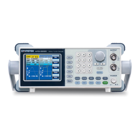
All manuals and user guides at all-guides.com GETTING STARTED Panel Overview Front Panel LCD Display Function keys, Scroll Wheel Arrow keys Output Return key Terminals AFG-2225 ... - Page 14 All manuals and user guides at all-guides.com AFG-2225 User Manual The UTIL key is used to access the save and recall options, update and view the firmware version, access the calibration options, output impedance settings and frequency meter. ARB is used to set the arbitrary ...
- Page 15 All manuals and user guides at all-guides.com GETTING STARTED The scroll wheel is used to edit Scroll Wheel values and parameters. Decrease Increase The digital keypad is used to enter Keypad values and parameters. The keypad ...
- Page 16 All manuals and user guides at all-guides.com AFG-2225 User Manual Rear Panel Power socket input Input Terminals rr v ost z rr ountr USB Host port USB Device port Trigger output External trigger input. Used to...
- Page 17 All manuals and user guides at all-guides.com GETTING STARTED USB type-A host port. USB Host Host USB type-B device port is used to USB Device Device connect the function generator to a Port PC for remote control. Frequency counter input. Counter Input Trigger Trigger...
- Page 18 All manuals and user guides at all-guides.com AFG-2225 User Manual Display Status Tabs Parameter Windows Soft Menu Keys Waveform Display The Parameter display and edit window. Parameter Windows Displays the current channel and setting status. Status Tabs Waveform Display Used to display the waveform...
-
Page 19: Setting Up The Function Generator
turn Place the AFG-2225 horizontally, Or tilt the stand. Place the handle vertically to hand carry. - Page 20 All manuals and user guides at all-guides.com AFG-2225 User Manual 1. Connect the power cord to Power Up the socket on the rear panel. 2. Turn on the power switch on the front panel. 3. When the power switch is turned on the screen displays the loading screen.
-
Page 21: Quick Reference
All manuals and user guides at all-guides.com QUICK REFERENCE UICK REFERENCE This chapter describes the operation shortcuts, built-in help and factory default settings. This chapter is to be used as a quick reference, for detailed explanations on parameters, settings and limitations, please see the operation chapters. - Page 22 All manuals and user guides at all-guides.com AFG-2225 User Manual Tracking ................43 Menu Tree ................. 44 Waveform ................44 ARB-Display................45 ARB-Edit ................46 ARB- Built In ................. 46 ARB-Save ................47 ARB-Load ................47 ARB-Output ................48 MOD ..................48 SWEEP ..................
-
Page 23: How To Use The Digital Inputs
All manuals and user guides at all-guides.com QUICK REFERENCE How to use the Digital Inputs The AFG-2225 has three main types of digital Background inputs: the number pad, arrow keys and scroll wheel. The following instructions will show you how to use the digital inputs to edit parameters. - Page 24 All manuals and user guides at all-guides.com AFG-2225 Series User Manual 4. Alternatively, the number pad can be used to set the value of a highlighted parameter. ...
-
Page 25: How To Use The Help Menu
All manuals and user guides at all-guides.com QUICK REFERENCE How to use the Help Menu Every key and function has a detailed description Background in the help menu. 1. Press UTIL 2. Press System (F3) ystm 3. Press Help (F2) lp ... - Page 26 All manuals and user guides at all-guides.com AFG-2225 Series User Manual Burst Function Provides help on the Burst function. DSO Link Provides help on DSO link. 5. For example, select item 4 to see help on the sweep functions. 6. Use the scroll wheel to navigate the help information.
-
Page 27: Selecting A Waveform
All manuals and user guides at all-guides.com QUICK REFERENCE Selecting a Waveform Square Wave Example: Square wave, 3Vpp, 75% duty cycle, 1kHz. 1. Press Waveform and Output: quar select Square (F2). 2. Press Duty (F1), 7 + 5 uty Ω... -
Page 28: Sine Wave
All manuals and user guides at all-guides.com AFG-2225 Series User Manual 4. Press the AMPL key then 5 +VPP (F5). 5. Press the Output key. OUTPUT Sine Wave Example: Sine Wave, 10Vpp,100kHz 1. Press the Waveform Output: ... -
Page 29: Modulation
All manuals and user guides at all-guides.com QUICK REFERENCE Modulation Example: AM modulation. 100Hz modulating square wave. 1kHz Sine wave carrier. 80% modulation depth. 1. Press the MOD key Output: and select AM (F1). 2. Press Waveform and ... - Page 30 All manuals and user guides at all-guides.com AFG-2225 Series User Manual 10. Press the output key. OUTPUT Example: FM modulation. 100Hz modulating square wave. 1kHz Sine wave carrier. 100 Hz frequency deviation. Internal Source. 1. Press the MOD key Output: ...
-
Page 31: Fsk Modulation
All manuals and user guides at all-guides.com QUICK REFERENCE 9. Press MOD, FM (F2), our Source (F1), INT (F1). 10. Press the Output key. OUTPUT FSK Modulation Example: FSK modulation. 100Hz Hop frequency. 1kHz Carrier wave. Sine wave. 10 Hz Rate. Internal Source. 1. -
Page 32: Pm Modulation
All manuals and user guides at all-guides.com AFG-2225 Series User Manual 9. Press the output key. OUTPUT PM Modulation Example: PM modulation. 800Hz sinusoidal carrier wave. 15 kHz modulating sine wave. 50˚ phase deviation. Internal Source. 1. Press Waveform and Output: ... -
Page 33: Sum Modulation
All manuals and user guides at all-guides.com QUICK REFERENCE 10. Press the Output key. OUTPUT SUM Modulation Example: SUM modulation. 100Hz modulating square wave, 1kHz sinusoidal carrier wave, 50% SUM amplitude, internal source. 1. Press the MOD key, Output: ... -
Page 34: Sweep
All manuals and user guides at all-guides.com AFG-2225 Series User Manual 9. Press MOD, SUM our (F5), Source (F1), INT (F1). 10. Press the Output key. OUTPUT Sweep Example: Frequency Sweep. Start Frequency 10mHz, Stop frequency 1MHz. Log sweep, 1 second sweep, Marker Frequency 550 Hz, Manual Trigger. -
Page 35: Burst
All manuals and user guides at all-guides.com QUICK REFERENCE 9. Press 5 + 5 + 0 + Hz z (F3). 10. Press the Output key. OUTPUT 11. Press Sweep, Source our anual (F1), Manual (F3), rr Trigger (F1). - Page 36 All manuals and user guides at all-guides.com AFG-2225 Series User Manual 9. Press Burst, N Cycle yl st (F1), TRIG set (F5), lay Delay (F4). 10. Press 1 + 0 + uSEC u (F2). 11. Press Burst, N Cycle ...
-
Page 37: Arb
All manuals and user guides at all-guides.com QUICK REFERENCE ARB–Add Built-In Waveform Example: ARB Mode, Exponential Rise. Start 0, Length 100, Scale 327. 1. Press ARB, Built in Output: ultn av (F3), Wave (F4), ath lt Math(F2), use the scroll wheel to select Ω... -
Page 38: Arb- Add Line
All manuals and user guides at all-guides.com AFG-2225 Series User Manual 3. Press Data (F2), ata ntr 3+0+0, Enter (F2). ARB- Add Line Example: ARB Mode, Add line, Address:Data (10:30, 50:100) 1. Press ARB, Edit (F2), Output: ... - Page 39 All manuals and user guides at all-guides.com QUICK REFERENCE 3. Press Length (F2), 1 + nth 0 + 0, Enter (F2), ntr Return Return.
-
Page 40: Utility Menu
All manuals and user guides at all-guides.com AFG-2225 Series User Manual Utility Menu Save Example: Save to Memory file #5. 1. Press UTIL, Memory mory tor (F1), Store (F1). 2. Choose a setting using the scroll wheel on and press Done (F5). -
Page 41: Frequency Counter
All manuals and user guides at all-guides.com QUICK REFERENCE Frequency Counter Frequency Counter Example: Turn on the frequency counter. Gate time: 1 second. 1. Press UTIL, Counter Output: N/A ountr (F5). Input: 2. Press Gate Time (F1), Trigger atm ... -
Page 42: Coupling
All manuals and user guides at all-guides.com AFG-2225 Series User Manual Coupling Frequency Coupling Example: Frequency Coupling 1. Press UTIL, Dual ualhan Chan (F4) to enter the coupling function. 2. Press Freq Cpl (F1) to rqpl select the frequency coupling function. -
Page 43: Tracking
All manuals and user guides at all-guides.com QUICK REFERENCE 3. Couples the amplitude and offset between both channels. Any changes in amplitude in the current channel are reflected in the other channel. Tracking Example: Tracking 1. Press UTIL, Dual ualhan ... -
Page 44: Menu Tree
All manuals and user guides at all-guides.com AFG-2225 Series User Manual Menu Tree Conventions Use the menu trees as a handy reference for the function generator functions and properties. The AFG- 2225 menu system is arranged in a hierarchical tree. -
Page 45: Arb-Display
All manuals and user guides at all-guides.com QUICK REFERENCE ARB-Display Display Horizon Vertical Next Page Back Page Overview Start Clear Clear Enter Enter Length High Clear Clear Enter Enter Center Center Clear Clear Enter Enter Zoom in Zoom in Zoom out Zoom out... -
Page 46: Arb-Edit
All manuals and user guides at all-guides.com AFG-2225 Series User Manual ARB-Edit Edit Point Line Copy Clear Protect Address Start ADD Start Start Done Clear Clear Clear Clear Enter Enter Enter Enter Start Data Start Data Length Length Clear... -
Page 47: Arb-Save
All manuals and user guides at all-guides.com QUICK REFERENCE ARB-Save More Save Start Length Memory Done Clear Clear Enter Enter Select Select New Folder Enter Char Back Space Save New File Enter Char Back Space Save ARB-Load More Load Memory Done... -
Page 48: Arb-Output
All manuals and user guides at all-guides.com AFG-2225 Series User Manual ARB-Output Output Start Length Clear Clear Enter Enter Source Source Source Source Source Depth Freq Dev Hop Freq Phase Dev SUM Ampl Degree AM Freq PM Freq... -
Page 49: Sweep
All manuals and user guides at all-guides.com QUICK REFERENCE SWEEP Source Type Start Stop More Linear Go to the Sweep - More menu Manual Trigger SWEEP- More wp More SWP Time Span Center Marker mSEC Freq ON/OFF... -
Page 50: Burst- N Cycle
All manuals and user guides at all-guides.com AFG-2225 Series User Manual Burst- N Cycle urst N Cycle Cycles Infinite Phase Period TRIG Setup Clear Clear uSEC Degree mSEC Rise Fall Manual Trigger Delay nSEC uSEC mSEC TRIG out Rise Fall ON/OFF Burst –... -
Page 51: Util
All manuals and user guides at all-guides.com QUICK REFERENCE UTIL Memory Cal. System Dual Chan Counter Store Self Test Language Freq Cpl Gate Time Done English Software 0.01 Sec Offset 0.1 Sec Recall Version Help Ratio 1 Sec Upgrade Done 10 Sec Select... -
Page 52: Default Settings
All manuals and user guides at all-guides.com AFG-2225 Series User Manual Default Settings The Preset key is used to restore the default panel rst settings. Function Sine Wave Output Settings Frequency 1kHz Amplitude 3.000 Vpp Offset 0.00V dc Output units Output terminal 50Ω... - Page 53 All manuals and user guides at all-guides.com QUICK REFERENCE Burst frequency 1kHz Burst Ncycle Burst period 10ms Burst starting phase 0˚ Burst status Power off signal System Settings Display mode Error queue Cleared Memory settings No change Output Trigger source Internal (immediate) Trigger Calibration Menu...
-
Page 54: Operation
All manuals and user guides at all-guides.com AFG-2225 Series User Manual PERATION The Operation chapter shows how to output basic waveform functions. For details on modulation, sweep, burst and arbitrary waveforms, please see the Modulation and Arbitrary waveform chapters on pages 64 and 147. -
Page 55: Select A Waveform
All manuals and user guides at all-guides.com OPERATION Select a Waveform The AFG-2225 can output 5 standard waveforms: sine, square, pulse, ramp and noise. Sine Wave Panel Operation 1. Press the Waveformkey. 2. Press F1 (Sine). n... -
Page 56: Square Wave
All manuals and user guides at all-guides.com AFG-2225 Series User Manual Square Wave Panel Operation 1. Press the Waveform key. 2. Press F2 (Square) to create a quar square waveform. 3. Press F1 (Duty). The Duty uty parameter will be highlighted in the parameter window. -
Page 57: Setting The Pulse Width
All manuals and user guides at all-guides.com OPERATION Setting the Pulse Width Panel Operation 1. Press the Waveform key. 2. Press F3 (Pulse) to create a uls pulse width waveform. 3. Press F1 (Width). The Width dth parameter will be highlighted in the parameter window. -
Page 58: Setting A Ramp Waveform
All manuals and user guides at all-guides.com AFG-2225 Series User Manual 5. Press F2~F5 choose the unit n range. Range Pulse Width 20ns~1999.9s Frequency ≤ 25MHz: 20ns Minimum Pulse Width Note pulse width. Frequency ≤ 100 kHZ: 1/4096 duty cycle. -
Page 59: Selecting A Noise Waveform
All manuals and user guides at all-guides.com OPERATION 4. Use the arrow keys and scroll wheel or number pad to enter the symmetry percentage. 5. Press F2 (%) to choose % ... -
Page 60: Setting The Frequency
All manuals and user guides at all-guides.com AFG-2225 Series User Manual Setting the Frequency Panel Operation 1. Press the FREQ/Rate key. / 2. The FREQ parameter will become highlighted in the parameter window. 3. Use the arrow keys and scroll ... - Page 61 All manuals and user guides at all-guides.com OPERATION Ramp wave 1μHz~1MHz...
-
Page 62: Setting The Amplitude
All manuals and user guides at all-guides.com AFG-2225 Series User Manual Setting the Amplitude Panel Operation 1. Press the AMPL key. 2. The AMPL parameter will become highlighted in the parameter window. 3. Use the arrow keys and scroll ... -
Page 63: Setting The Dc Offset
All manuals and user guides at all-guides.com OPERATION Setting the DC Offset Panel Operation 1. Press the DC Offset key. 2. The DC Offset parameter will become highlighted in the parameter window. 3. Use the arrow keys and scroll ... -
Page 64: Modulation
All manuals and user guides at all-guides.com AFG-2225 Series User Manual ODULATION The AFG-2225 Series Arbitrary Function Generators are able to produce AM, FM, FSK, PM and SUM modulated waveforms. Depending on the type of waveform produced, different modulation parameters can be set. Only one modulation mode can be active at any one time. - Page 65 All manuals and user guides at all-guides.com MODULATION PM Wave Shape ..............94 PM Frequency ............... 95 Phase Deviation..............97 Select the PM Source ............98 SUM modulation ............. 100 Selecting SUM modulation ..........101 SUM Carrier Waveform ............101 SUM Carrier Frequency ............
-
Page 66: Amplitude Modulation (Am)
An AM waveform is produced from a carrier waveform and a modulating waveform. The amplitude of the modulated carrier waveform depends on the amplitude of the modulating waveform. The AFG-2225 function generator can set the carrier frequency, amplitude and offset as well as internal or external modulation sources. -
Page 67: Selecting Am Modulation
All manuals and user guides at all-guides.com MODULATION Selecting AM Modulation Panel Operation 1. Press the MOD key. 2. Press F1 (AM). AM Carrier Shape Sine, square, ramp, pulse or arbitrary waveforms Background can be used as the carrier shape. The default waveform shape is set to sine. -
Page 68: Carrier Frequency
All manuals and user guides at all-guides.com AFG-2225 Series User Manual 3. See the Arbitrary waveform Select an Page 37 quick reference or chapter to Arbitrary Page 147 Waveform Carrier use an arbitrary waveform. Shape. Range AM Carrier Shape sine, square, Ramp,Pulse,... -
Page 69: Modulating Wave Shape
1 kHz Modulating Wave Shape The function generator can accept internal as well as external sources. The AFG-2225 has sine, square, triangle, up ramp and down ramp modulating waveform shapes. Sine waves are the default wave shape. 1. Press the MOD key. -
Page 70: Am Frequency
All manuals and user guides at all-guides.com AFG-2225 Series User Manual AM Frequency The frequency of the modulation waveform (AM Frequency) can be set from 2mHz to 20kHz. Panel Operation 1. Press the MOD key. 2. Press F1 (AM). - Page 71 All manuals and user guides at all-guides.com MODULATION 5. Use the arrow keys and scroll wheel or number pad to enter the AM frequency. 6. Press F1~F3 to select the mz kz frequency range.
-
Page 72: Modulation Depth
All manuals and user guides at all-guides.com AFG-2225 Series User Manual Modulation Depth Modulation depth is the ratio (as a percentage) of the unmodulated carrier amplitude and the minimum amplitude deviation of the modulated waveform. In other words, modulation depth is the maximum amplitude of the modulated waveform compared to the carrier waveform as a percentage. -
Page 73: Selecting The (Am) Modulation Source
All manuals and user guides at all-guides.com MODULATION Range Depth 0%~120% Default depth 100% Note When the modulation depth is greater than 100%, the output cannot exceed ±5VPeak (10kΩ load). If an external modulation source is selected, modulation depth is limited to ± 5V from the MOD INPUT terminal on the rear panel. - Page 74 All manuals and user guides at all-guides.com AFG-2225 Series User Manual Note If an external modulation source is selected, modulation depth is limited to ± 5V from the MOD INPUT terminal on the rear panel. For example, if modulation depth is set to 100%, then the maximum...
-
Page 75: Frequency Modulation (Fm)
A FM waveform is produced from a carrier waveform and a modulating waveform. The instantaneous frequency of the carrier waveform varies with the magnitude of the modulating waveform. When using the AFG-2225 function generator, only one type of modulated waveform can be created at any one time. -
Page 76: Selecting Frequency Modulation (Fm)
All manuals and user guides at all-guides.com AFG-2225 Series User Manual Selecting Frequency Modulation (FM) When FM is selected, the modulated waveform depends on the carrier frequency, the output amplitude and offset voltage. Panel Operation 1. Press the MOD key. -
Page 77: Fm Carrier Frequency
All manuals and user guides at all-guides.com MODULATION FM Carrier Frequency When using the AFG-2225 function generator, the carrier frequency must be equal to or greater than the frequency deviation. If the frequency deviation is set to value greater than the carrier frequency, the deviation is set to the maximum allowed. -
Page 78: Fm Wave Shape
1kHz FM Wave Shape The function generator can accept internal as well as external sources. The AFG-2225 has sine, square, triangle, positive and negative ramps (UpRamp, DnRamp) as the internal modulating waveform shapes. Sine is the default wave shape. 1. Select MOD. -
Page 79: Fm Frequency
All manuals and user guides at all-guides.com MODULATION FM Frequency The frequency of the modulation waveform (FM Frequency) can be set from 2mHz to 20kHz. Panel Operation 1. Press the MOD key. 2. Press F2 (FM). 3. Press F3 (FM Freq). rq ... - Page 80 All manuals and user guides at all-guides.com AFG-2225 Series User Manual 4. The FM Freq parameter will become highlighted in waveform display panel. 5. Use the arrow keys and scroll wheel or number pad to enter ...
-
Page 81: Frequency Deviation
All manuals and user guides at all-guides.com MODULATION Frequency Deviation The frequency deviation is the peak frequency deviation from the carrier wave and the modulated wave. Panel Operation 1. Press the MOD key. 2. Press F2 (FM). 3. -
Page 82: Selecting (Fm) Modulation Source
All manuals and user guides at all-guides.com AFG-2225 Series User Manual Range Frequency Deviation DC~25MHz DC~15MHz(square) DC~1MHz (Ramp) Default depth 100Hz Selecting (FM) Modulation Source The function generator will accept an internal or external source for FM modulation. The default source is internal. - Page 83 All manuals and user guides at all-guides.com MODULATION If an external modulating source is selected, the Note frequency deviation is limited to the ± 5V MOD INPUT terminal on the rear panel. The frequency deviation is proportional to the signal level of the modulation in voltage.
-
Page 84: Frequency Shift Keying (Fsk) Modulation
All manuals and user guides at all-guides.com AFG-2225 Series User Manual Frequency Shift Keying (FSK) Modulation Frequency Shift Keying Modulation is used to shift the frequency output of the function generator between two preset frequencies (carrier frequency, hop frequency). The frequency at which the... -
Page 85: Selecting Fsk Modulation
All manuals and user guides at all-guides.com MODULATION Selecting FSK Modulation When using FSK mode, the output waveform uses the default settings for carrier frequency, amplitude and offset voltage. Panel Operation 1. Press the MOD key. 2. Press F3 (FSK). ... -
Page 86: Fsk Carrier Frequency
All manuals and user guides at all-guides.com AFG-2225 Series User Manual FSK Carrier Frequency The maximum carrier frequency depends on the carrier shape. The default carrier frequency for all carrier shapes is 1kHz. The voltage level of the Trigger INPUT signal controls the output frequency when EXT is selected. -
Page 87: Fsk Hop Frequency
All manuals and user guides at all-guides.com MODULATION FSK Hop Frequency The default Hop frequency for all waveform shapes is 100 Hz. A square wave with a duty cycle of 50% is used for the internal modulation waveform. The voltage level of the Trigger INPUT signal controls the output frequency when EXT is selected. -
Page 88: Fsk Rate
All manuals and user guides at all-guides.com AFG-2225 Series User Manual 6. Press F1~F5 to select the uz z frequency range. Range Waveform Carrier Frequency Sine wave 1μHz~25MHz Square wave 1μHz~15MHz Ramp wave 1μHz~1MHz Pulse wave 500μHz~15MHz Default frequency... - Page 89 All manuals and user guides at all-guides.com MODULATION 5. The arrow keys and scroll wheel or number pad to enter the FSK rate. 6. Press F1~F4 to select the mz kz frequency unit.
-
Page 90: Fsk Source
AFG-2225 Series User Manual FSK Source The AFG-2225 accepts internal and external FSK sources, with internal as the default source. When the FSK source is set to internal, the FSK rate is configured using the FSK Rate function. When an external source is selected the FSK rate is equal to the frequency of the Trigger INPUT signal on the rear panel. -
Page 91: Phase Modulation (Pm)
All manuals and user guides at all-guides.com MODULATION Phase Modulation (PM) The phase deviation of the carrier waveform deviates from a reference phase value in proportion to changes in the modulating waveform. Only one mode of modulation can be enabled at any one time. If PM is enabled, any other modulation mode will be disabled. -
Page 92: Selecting Phase Modulation (Pm)
All manuals and user guides at all-guides.com AFG-2225 Series User Manual Selecting Phase Modulation (PM) When selecting PM, the current setting of the carrier frequency, the amplitude modulation frequency, output, and offset voltage must be considered. Panel Operation 1. Press the MOD key. -
Page 93: Pm Carrier Waveform
All manuals and user guides at all-guides.com MODULATION PM Carrier Waveform PM uses a sine wave as default. Noise and Pulse Background waveform cannot be used with phase modulation. Panel Operation 1. Press the Waveform key. 2. Press F1 ~ F4 to select the n... -
Page 94: Pm Wave Shape
All manuals and user guides at all-guides.com AFG-2225 Series User Manual Range Carrier Wave Carrier Frequency Sine wave 1μHz~25MH Square wave 1μHz~15MHz Ramp wave 1μHz~1MHz Default frequency 1 kHz PM Wave Shape The function generator can accept internal or external sources. The internal sources can include sine, square, triangle, up ramp and down ramp. -
Page 95: Pm Frequency
All manuals and user guides at all-guides.com MODULATION PM Frequency The frequency of the modulation waveform (PM Frequency) can be set from 2mHz to 20kHz. Panel Operation 1. Press the MOD key. 2. Press F4 (PM). 3. Press F3 (PM Freq). rq ... - Page 96 All manuals and user guides at all-guides.com AFG-2225 Series User Manual 5. Use the arrow keys and scroll wheel or number pad to enter the PM frequency. 6. Press F1~F3 to select the mz...
-
Page 97: Phase Deviation
All manuals and user guides at all-guides.com MODULATION Phase Deviation The maximum phase deviation depends on the the carrier wave frequency and the modulated waveform. 1. Press the MOD key. Panel operation 2. Press F4 (PM). 3. Press F2 (Phase Dev). hasv ... -
Page 98: Select The Pm Source
All manuals and user guides at all-guides.com AFG-2225 Series User Manual Range Phase deviation/shift 0~360° Defualt phase 180° Select the PM Source The function generator excepts internal or external sources for phase modulation. The default source is internal. Panel Operation 1. Press the MOD key. - Page 99 All manuals and user guides at all-guides.com MODULATION...
-
Page 100: Sum Modulation
All manuals and user guides at all-guides.com AFG-2225 Series User Manual SUM modulation Sum modulation adds a modulating signal to a carrier wave. Typically, sum modulation is used to add noise to a carrier wave. The modulating signal is added as a percentage of the carrier amplitude. -
Page 101: Selecting Sum Modulation
All manuals and user guides at all-guides.com MODULATION Selecting SUM modulation For SUM modulation, the modulated waveform amplitude and offset is determined by the carrier wave. Panel Operation 1. Press the MOD key. 2. Press F5 (SUM). SUM Carrier Waveform Background The SUM carrier waveform is a sinewave by... -
Page 102: Sum Carrier Frequency
All manuals and user guides at all-guides.com AFG-2225 Series User Manual SUM Carrier Frequency The maximum carrier frequency depends on the selected carrier waveform. The default carrier frequency is 1kHz. Panel Operation 1. Press the FREQ/Rate key to / select the carrier frequency. -
Page 103: Sum Waveform
All manuals and user guides at all-guides.com MODULATION SUM Waveform The function generator can accept internal and external sources. The AFG-2225 includes sine, square, triangle, UpRamp and DnRamp as internal sources. The default waveform is sine. Panel Operation 1. Press the MOD key. ... -
Page 104: Modulating Waveform Frequency
All manuals and user guides at all-guides.com AFG-2225 Series User Manual Modulating Waveform Frequency The frequency of the modulating waveform (SUM Frequency) can be set from 2mHz to 20kHz. Panel Operation 1. Press the MOD key. 2. Press F5 (SUM). -
Page 105: Sum Amplitude
All manuals and user guides at all-guides.com MODULATION SUM Amplitude The SUM amplitude is the offset (in percent relative to the carrier) of the signal that is added to the carrier. Panel Operation 1. Press the MOD key. 2. Press F5 (SUM). ... -
Page 106: Select The Sum Amplitude Source
All manuals and user guides at all-guides.com AFG-2225 Series User Manual Select the SUM Amplitude Source The signal generator can accept internal or external sources for the SUM amplitude modulation. Panel Operation 1. Press the MOD key. 2. Press F5 (SUM). - Page 107 All manuals and user guides at all-guides.com MODULATION...
-
Page 108: Frequency Sweep
All manuals and user guides at all-guides.com AFG-2225 Series User Manual Frequency Sweep The function generator can perform a sweep for sine, square or ramp waveforms, but not noise, and pulse. When Sweep mode is enabled, Burst or any other modulation modes will be disabled. When sweep is enabled, burst mode is automatically disabled. -
Page 109: Selecting Sweep Mode
All manuals and user guides at all-guides.com MODULATION Selecting Sweep Mode The Sweep button is used to output a sweep. If no settings have been configured, the default settings for output amplitude, offset and frequency are used. Setting Start and Stop Frequency The start and stop frequencies define the upper and lower sweep limits. - Page 110 All manuals and user guides at all-guides.com AFG-2225 Series User Manual Stop 4. Use the arrow keys and scroll wheel or number pad to enter the Stop/Start frequency. 5. Press F1~F5 to select the uz...
-
Page 111: Center Frequency And Span
All manuals and user guides at all-guides.com MODULATION Center Frequency and Span A center frequency and span can be set to determine the upper and lower sweep limits (start/stop). Panel Operation 1. Press the SWEEP key. 2. Press F5 (More). or... - Page 112 All manuals and user guides at all-guides.com AFG-2225 Series User Manual Range Center frequency 1μHz~25MHz (sine wave) 1μHz~1MHz (Ramp wave) 1μHz~15MHz (square wave) Span frequency DC~25MHz (sine wave) DC ~1MHz (Ramp wave) 1μHz~15MHz (square wave) Default center 550Hz Default span...
-
Page 113: Sweep Mode
All manuals and user guides at all-guides.com MODULATION Sweep Mode Sweep mode is used to select between linear or logarithmic sweeping. Linear sweeping is the default setting. Panel Operation 1. Press the SWEEP key. 2. Press F2 (Type). yp... -
Page 114: Sweep Time
All manuals and user guides at all-guides.com AFG-2225 Series User Manual Sweep Time The sweep time is used to determine how long it takes to perform a sweep from the start to stop frequencies. The function generator automatically determines the number of discrete frequencies used in the scan depending on the length of the scan. -
Page 115: Marker Frequency
All manuals and user guides at all-guides.com MODULATION Range Sweep time 1ms ~ 500s Default time Marker Frequency The marker frequency is the frequency at which the marker signal goes low (The marker signal is high at the start of each sweep). The marker signal is output from the Trigger OUT terminal on the rear panel. -
Page 116: Sweep Trigger Source
All manuals and user guides at all-guides.com AFG-2225 Series User Manual 7. Use the arrow keys and scroll wheel or number pad to enter the frequency. 8. Press F1~F5 to select the uz... - Page 117 All manuals and user guides at all-guides.com MODULATION 3. To select the trigger source, anual press F1 (Internal), F2 (External) or F3 (Manual). 4. Press Return to return to the Return previous menu. Using the Internal source will produce a Note continuous sweep using the sweep time settings.
-
Page 118: Burst Mode
All manuals and user guides at all-guides.com AFG-2225 Series User Manual Burst Mode The function generator can create a waveform burst with a designated number of cycles. Burst mode supports sine, square and ramp waveforms. -
Page 119: Selecting Burst Mode
All manuals and user guides at all-guides.com MODULATION Selecting Burst Mode When burst mode is selected, any modulation or sweep modes will be automatically disabled. If no settings have been configured, the default settings for output amplitude, offset and frequency are used. -
Page 120: Burst Frequency
All manuals and user guides at all-guides.com AFG-2225 Series User Manual In Gated mode, burst count, burst cycle and trigger source are ignored. If a trigger is input, then the trigger will be ignored and will not generate any errors. -
Page 121: Burst Cycle/Burst Count
All manuals and user guides at all-guides.com MODULATION Range Frequency 1uHz~25MHz Freqency – Ramp 1uHz~1MHz Default 1kHz Waveform frequency and burst period are not the Note same. The burst period is the time between the bursts in N-Cycle mode. Burst Cycle/Burst Count The burst cycle (burst count) is used to define the number of cycles that are output for a burst waveform. - Page 122 All manuals and user guides at all-guides.com AFG-2225 Series User Manual 5. Use the arrow keys and scroll wheel or number pad to enter the number of cycles. 6. Press F2 to select the Cyc y...
-
Page 123: Infinite Burst Count
All manuals and user guides at all-guides.com MODULATION Infinite Burst Count Panel Operation 1. Press the Burst key. 2. Press F1 (N Cycle). yl 3. Press F2 (Infinite). nfnt Note Infinite burst is only available when using manual triggering. - Page 124 All manuals and user guides at all-guides.com AFG-2225 Series User Manual 3. Press F4 (Period). rod 4. The Period parameter will become highlighted in the Waveform Display area. 5. Use the arrow keys and scroll wheel or number pad to enter ...
-
Page 125: Burst Phase
All manuals and user guides at all-guides.com MODULATION Burst Phase Burst Phase defines the starting phase of the burst waveform. The default is 0˚. Panel Operation 1. Press the Burst key. 2. Press F1 (N Cycle). yl 3. Press F3 (Phase). has... -
Page 126: Burst Trigger Source
All manuals and user guides at all-guides.com AFG-2225 Series User Manual When using sine, square, triangle or ramp Note waveforms, 0˚ is the point where the waveforms are at zero volts. 0˚ is the starting point of a waveform. For sine, square or Triangle, Ramp waveforms, 0˚... - Page 127 All manuals and user guides at all-guides.com MODULATION Manual If a manual source is selected, the rr Triggering Trigger softkey (F1) must be pressed each time to output a burst. When the internal trigger source is chosen, the Note burst is output continuously at a rate defined by the burst period setting.
-
Page 128: Burst Delay
All manuals and user guides at all-guides.com AFG-2225 Series User Manual Burst Delay Panel Operation 1. Press the Burst key. 2. Press F1 (N Cycle). yl 3. Press F5 (TRIG set). st 4. Press F4 (Delay). lay ... -
Page 129: Burst Trigger Output
All manuals and user guides at all-guides.com MODULATION Range Delay time 0s~655350nS Default Burst Trigger Output The Trig Out terminal on the rear panel can be used for burst or sweep modes to output a rising edge TTL compatible trigger signal. By default the trigger signal is rising edge. - Page 130 All manuals and user guides at all-guides.com AFG-2225 Series User Manual...
-
Page 131: Secondary System Function Settings
All manuals and user guides at all-guides.com SECONDARY SYSTEM FUNCTION SETTINGS ECONDARY SYSTEM FUNCTION SETTINGS The secondary system functions are used to store and recall settings, view help files, view the software version, update the firmware, set the buzzer. Save and Recall ............... 132 System and Settings ............ -
Page 132: Save And Recall
All manuals and user guides at all-guides.com AFG-2225 Series User Manual Save and Recall The AFG-2225 has non-volatile memory to store instrument state and ARB data. There are 10 memory files numbered 0~9. Each memory file can either store arbitrary waveform data (ARB), settings or both. - Page 133 All manuals and user guides at all-guides.com SECONDARY SYSTEM FUNCTION SETTINGS Time Shape Start frequency Phase deviation Stop frequency Frequency Center frequency Burst Type Span frequency Source Marker frequency Trigger out ...
- Page 134 All manuals and user guides at all-guides.com AFG-2225 Series User Manual 4. Choose a file operation: Press F1 to store a file, press tor F2 to recall a file, or press F3 all to delete a file. ...
- Page 135 All manuals and user guides at all-guides.com SECONDARY SYSTEM FUNCTION SETTINGS 9. Press F1 (Done) to confirm on the deletion of all files.
-
Page 136: System And Settings
All manuals and user guides at all-guides.com AFG-2225 Series User Manual System and Settings There are a number of miscellaneous settings and firmware settings that can be configured. Viewing and Updating the Firmware 1. Press the UTIL key. View Version ... - Page 137 All manuals and user guides at all-guides.com SECONDARY SYSTEM FUNCTION SETTINGS Setting the Buzzer Sound Turns the beeper on or off. Background Panel Operation 1. Press the UTIL key. 2. Press F3 (System). ystm 3. PressF3 (Beep) to toggle the ...
- Page 138 All manuals and user guides at all-guides.com AFG-2225 Series User Manual Frequency Coupling Example: Frequency Coupling 1. Press UTIL, F4 (Dual Chan) to ualhan enter the coupling function. 2. Press F1 (Freq Cpl) to select rqpl the frequency coupling function.
- Page 139 All manuals and user guides at all-guides.com SECONDARY SYSTEM FUNCTION SETTINGS 4. Input an offset value of 1kHz. uz z Press F1~ F5 to select the units. The frequency of channel 2 becomes 2kHz (CH2=CH1 + Offset). 5. Change the frequency coupling mode to Ratio. Set the ratio to 2.
- Page 140 All manuals and user guides at all-guides.com AFG-2225 Series User Manual Amplitude Coupling Example: Amplitude Coupling 1. The following assumes that the amplitude has already been set to 4Vpp with a DC offset of 1Vdc. 2. Press UTIL, F4 (Dual ...
- Page 141 All manuals and user guides at all-guides.com SECONDARY SYSTEM FUNCTION SETTINGS 1. The method for outputting a square wave has been previously described. Use this method to output a 2kHz squarewave from CH1 with an amplitude of 5Vpp and a DC offset of 1Vdc. 2.
- Page 142 All manuals and user guides at all-guides.com AFG-2225 Series User Manual...
-
Page 143: Channel Settings
Selecting the Output Phase ..........144 Synchronizing the Phase ............ 145 DSO Link ................146 Output Impedance The AFG-2225 has selectable output impedances: Background 50Ω or high impedance. The default output impedance is 50Ω. The output impedances are to be used as a reference only. If the actual load impedance is different to that specified, then the actual amplitude and offset will vary accordingly. - Page 144 All manuals and user guides at all-guides.com AFG-2225 Series User Manual 3. Select F1 (50 OHM) or F2 h (High Z) to select the output impedance. Selecting the Output Phase 1. Press the CH1/CH2 key. Panel operation ...
- Page 145 5. Press F5 (Degree). r Synchronizing the Phase Synchronizes both the outputs on the AFG-2225. Background Panel Operation 1. Press the CH1/CH2 key. 2. Press F4 (Phase). has 3. Press F2 (S_Phase) to _has...
- Page 146 All manuals and user guides at all-guides.com AFG-2225 Series User Manual DSO Link DSO Link enables the AFG-2225 to receive lossless Background data from a GDS-2000 Series DSO to create ARB data. 1. Connect the AFG-2225 USB host port to the GDS-2000’s USB B device port.
-
Page 147: Arbitrary Waveforms
All manuals and user guides at all-guides.com ARBITRARY WAVEFORMS RBITRARY WAVEFORMS The AFG-2225 can create user-defined arbitrary waveforms with a sample rate of 120MHz. Each waveform can include up to 4k of data points with a vertical range of ±511. -
Page 148: Inserting Built-In Waveforms
All manuals and user guides at all-guides.com AFG-2225 Series User Manual Inserting Built-In Waveforms The AFG-2225 includes 66 common waveforms, such as math waveforms, windowing functions and engineering waveforms. Create an AbsAtan Waveform Panel Operation 1. Press the ARB key. - Page 149 All manuals and user guides at all-guides.com ARBITRARY WAVEFORMS Below an Absatan wave created at start:0, Length: 33, Scale: 511...
-
Page 150: Display An Arbitrary Waveform
All manuals and user guides at all-guides.com AFG-2225 Series User Manual Display an Arbitrary Waveform Set the Horizontal Display Range The horizontal window bounds can be set in one of two ways: Using a start point and length, or a center point and length. - Page 151 All manuals and user guides at all-guides.com ARBITRARY WAVEFORMS 10. Repeat steps 4~9 for Length Setting the nth (F2). Length 11. Repeat steps 4~9 for Center Using a Center ntr (F3). Point 12. To zoom into the arbitrary Zoom in oomn ...
-
Page 152: Set The Vertical Display Properties
All manuals and user guides at all-guides.com AFG-2225 Series User Manual Set the Vertical Display Properties Like the horizontal properties, the vertical display properties of the waveform display can be created in two ways: Setting high and low values, or setting the center point. - Page 153 All manuals and user guides at all-guides.com ARBITRARY WAVEFORMS 11. Repeat steps 4~9 for Center Setting the Center ntr (F3). Point 12. To zoom in from the center of Zoom oomn the arbitrary waveform, press F4 (Zoom in). The Zoom in function will reduce the length by half each time the function is used.
-
Page 154: Page Navigation (Back Page)
All manuals and user guides at all-guides.com AFG-2225 Series User Manual Page Navigation (Back Page) When viewing the waveform, the display window Background can be moved forward and backward using the Next/Back Page functions. Panel Operation 1. Press the ARB key. - Page 155 All manuals and user guides at all-guides.com ARBITRARY WAVEFORMS...
-
Page 156: Page Navigation (Next Page)
All manuals and user guides at all-guides.com AFG-2225 Series User Manual Page Navigation (Next Page) When viewing the waveform, the display window Background can be moved forward and backward using the Next/Back Page functions. Panel Operation 1. Press the ARB key. - Page 157 All manuals and user guides at all-guides.com ARBITRARY WAVEFORMS...
-
Page 158: Display
All manuals and user guides at all-guides.com AFG-2225 Series User Manual Display Panel Operation 1. Press the ARB key. 2. Press F1 (Display). splay 3. To make the display window vrvw cover the whole waveform, press F5 (Overview). -
Page 159: Editing An Arbitrary Wavefrom
All manuals and user guides at all-guides.com ARBITRARY WAVEFORMS Editing an Arbitrary Wavefrom Adding a Point to an Arbitrary Waveform The AFG-2225 has a powerful editing function that Background allows you to create points or lines anywhere on the waveform. -
Page 160: Adding A Line To An Arbitrary Waveform
In the following figure the edited address is shown in red. Address 100,Data 200 Adding a Line to an Arbitrary Waveform The AFG-2225 has a powerful editing function that Background allows you to create points or lines anywhere on the waveform. - Page 161 All manuals and user guides at all-guides.com ARBITRARY WAVEFORMS Panel Operation 1. Press the ARB key. 2. Press F2 (Edit). dt 3. Press F2 (Line). n 4. Press F1 (Start ADD). tart 5. The Start Address parameter will be highlighted in red.
-
Page 162: Copy A Waveform
All manuals and user guides at all-guides.com AFG-2225 Series User Manual The red line was created below with the following properties: Start Address: 0, Start Data: 0 Stop Address: 32, Stop Data: 0 Copy a Waveform Panel Operation 1. Press the ARB key. - Page 163 All manuals and user guides at all-guides.com ARBITRARY WAVEFORMS 6. The the arrow keys and scroll wheel or number pad to enter the Copy From address. 7. Press F2 (Enter) to save the ntr ...
-
Page 164: Clear The Waveform
All manuals and user guides at all-guides.com AFG-2225 Series User Manual Clear the Waveform Panel Operation 1. Press the ARB key. 2. Press F2 (Edit). dt 3. Press F4 (Clear). lar 4. Press F1 (Start). tart ... - Page 165 All manuals and user guides at all-guides.com ARBITRARY WAVEFORMS 11. Press F4 (ALL) to delete the Delete All whole waveform. 12. Press F1 (Done) again to on confirm the deletion. 13. Press Return return to the Return previous menu.
-
Page 166: Arb Protection
All manuals and user guides at all-guides.com AFG-2225 Series User Manual The result after the whole waveform is deleted: ARB Protection The protection function designates an area of the arbitrary waveform that cannot be altered. Panel Operation 1. Press the ARB key. - Page 167 All manuals and user guides at all-guides.com ARBITRARY WAVEFORMS 6. Use the arrow keys and scroll wheel or number pad to enter the Protect Start address. 7. Press F2 (Enter) to save the ntr ...
- Page 168 All manuals and user guides at all-guides.com AFG-2225 Series User Manual Below, the protected areas of the waveform are shown with an orange background: Start:0, Length: 100.
-
Page 169: Ouput An Arbitrary Waveform
All manuals and user guides at all-guides.com ARBITRARY WAVEFORMS Ouput an Arbitrary Waveform The arbitrary waveform generator can output up to 4k points (2~4096). Ouput Arbitrary Waveform Panel Operation 1. Press the ARB key. 2. Press F4 (Output). utput 3. - Page 170 All manuals and user guides at all-guides.com AFG-2225 Series User Manual The front panel terminal will output the following waveform. Start 0,Length 500...
-
Page 171: Saving/Loading An Arbitrary Waveform
All manuals and user guides at all-guides.com ARBITRARY WAVEFORMS Saving/Loading an Arbitrary Waveform The AFG-2225 can save and load arbitrary waveforms from 10 internal memory slots. Arbitrary waveforms can also be saved and loaded from a USB memory stick. Saving a Waveform to Internal Memory Panel Operation 1. -
Page 172: Saving A Waveform To Usb Memory
All manuals and user guides at all-guides.com AFG-2225 Series User Manual 11. Select a memory file using the scroll wheel. Memory0~Memory9 12. Press F1 (Select) to save the lt selected memory file. 13. Press Return to return to the Return previous menu. - Page 173 All manuals and user guides at all-guides.com ARBITRARY WAVEFORMS 5. The Start propery will become highlighted in red. 6. Use the arrow keys and scroll wheel or number pad to enter the Start address. ...
- Page 174 All manuals and user guides at all-guides.com AFG-2225 Series User Manual New Folder: NEW_FOL 3. Use the scroll wheel to move the cursor. 4. Use F1 (Enter Char) or F2 ntrhar akspa (Backspace) to create a folder name.
-
Page 175: Load A Waveform From Internal Memory
All manuals and user guides at all-guides.com ARBITRARY WAVEFORMS 3. Use the scroll wheel to move the cursor. 4. Use F1 (Enter Char) or F2 ntrhar akspa (Backspace) to create a file name. 5. Press F5 (Save) to save the file av... - Page 176 All manuals and user guides at all-guides.com AFG-2225 Series User Manual 5. Use the scroll whell to choose a memory file. 6. Press Select to load the lt selected memory file. 7. Press F3 (To) to choose the ...
- Page 177 All manuals and user guides at all-guides.com ARBITRARY WAVEFORMS...
-
Page 178: Load A Waveform From Usb
All manuals and user guides at all-guides.com AFG-2225 Series User Manual Load a Waveform from USB Panel Operation 1. Press the ARB key. 2. Press F5 (More). or 3. Press F2 (Load). oad 4. Press F2 (USB). - Page 179 All manuals and user guides at all-guides.com ARBITRARY WAVEFORMS Below the file AFG.CSV is selected using the scroll wheel loaded to position 0.
-
Page 180: Remote Interface
All manuals and user guides at all-guides.com AFG-2225 Series User Manual EMOTE INTERFACE Establishing a Remote Connection ........181 Configure USB interface ............ 181 Remote control terminal connection ......... 182 Command Syntax ............... 184... -
Page 181: Establishing A Remote Connection
All manuals and user guides at all-guides.com REMOTE INTERFACE Establishing a Remote Connection The AFG-2225 supports USB remote connections. Configure USB interface PC side connector Type A, host configuration Type B, slave AFG-2225 side connector 1.1/2.0 (full speed) Speed Panel Operation 1. Connect the USB cable to the rear panel USB B (slave) port. -
Page 182: Remote Control Terminal Connection
All manuals and user guides at all-guides.com AFG-2225 Series User Manual Remote control terminal connection Invoke the terminal application such as MTTTY Terminal application (Multi-Threaded TTY). For USB, set the COM port, baud rate, stop bit, data bit, and parity accordingly. - Page 183 All manuals and user guides at all-guides.com REMOTE INTERFACE...
-
Page 184: Command Syntax
All manuals and user guides at all-guides.com AFG-2225 Series User Manual Command Syntax IEEE488.2, 1992 (fully compatible) Compatible standard SCPI, 1994 (partially compatible) The SCPI standard is an ASCII based standard that Command Tree defines the command syntax and structure for programmable instruments. - Page 185 All manuals and user guides at all-guides.com REMOTE INTERFACE A query is a simple or compound Query command followed by a question mark (?). A parameter (data) is returned. The maximum or minimum value for a parameter can also be queried where applicable.
- Page 186 All manuals and user guides at all-guides.com AFG-2225 Series User Manual 1: command header Command offset SOURce1:DCOffset < >LF Format 2: single space 3: parameter 4: message terminator Square Brackets [] Commands that contain squares brackets indicate that the contents are optional. The function of the command is the same with or without the square bracketed items.
- Page 187 All manuals and user guides at all-guides.com REMOTE INTERFACE NRf type with a 1, 1.5, 4.5e-1 <NRf+> suffix including <Numeric> MAX, MIN, MINimum, MAXimum or DEFault parameters. Arbitrary ASCII <aard> characters. Discrete ASCII IMM, EXT, <discrete> character parameters NRf+ type 1 KHZ, 1.0 HZ, <frequency>...
- Page 188 All manuals and user guides at all-guides.com AFG-2225 Series User Manual A space is used to separate a Command Space parameter from a Separators keyword/command header. A colon is used to separate Colon (:) keywords on each node. A semi colon is used to separate Semicolon (;)
-
Page 189: Command List
All manuals and user guides at all-guides.com REMOTE INTERFACE Command List System Commands ............193 SYSTem:ERRor?..............193 *IDN? ................. 193 *RST..................194 SYSTem:VERSion? .............. 194 *OPC .................. 194 *OPC? ................. 195 *WAI ................... 195 Status Register Commands ..........196 *CLS ..................196 *ESE .................. - Page 190 All manuals and user guides at all-guides.com AFG-2225 Series User Manual SOURce[1|2]:AM:SOURce ..........219 SOURce[1|2]:AM:INTernal:FUNCtion ....... 220 SOURce[1|2]:AM:INTernal:FREQuency ......221 SOURce[1|2]:AM:DEPTh ............ 221 Frequency Modulation (FM) Commands ......223 FM Overview ..............223 SOURce[1|2]:FM:STATe ............. 224 SOURce[1|2]:FM:SOURce ..........224 SOURce[1|2]:FM:INTernal:FUNCtion ....... 225 SOURce[1|2]:FM:INTernal:FREQuency ......
- Page 191 All manuals and user guides at all-guides.com REMOTE INTERFACE Burst Mode Overview ............249 SOURce[1|2]:BURSt:STATe ..........251 SOURce[1|2]:BURSt:MODE ..........251 SOURce[1|2]:BURSt:NCYCles ..........252 SOURce[1|2]:BURSt:INTernal:PERiod ....... 253 SOURce[1|2]:BURSt:PHASe ..........254 SOURce[1|2]:BURSt:TRIGger:SOURce ......254 SOURce[1|2]:BURSt:TRIGger:DELay ........255 SOURce[1|2]:BURSt:TRIGger:SLOPe ......... 256 SOURce[1|2]:BURSt:GATE:POLarity ........257 SOURce[1|2]:BURSt:OUTPut:TRIGger:SLOPe ....
- Page 192 All manuals and user guides at all-guides.com AFG-2225 Series User Manual MEMory:STATe:DELete ALL ..........272...
-
Page 193: System Commands
Returns an error string. *IDN? System Query Returns the function generator manufacturer, Description model number, serial number and firmware version number in the following format: GW INSTEK,AFG-2225,SN:XXXXXXXX,Vm.mm Query Syntax *IDN? Return parameter <string> Example *IDN? GW INSTEK,AFG-2225,SN:XXXXXXXX,Vm.mm Returns the identification of the function... -
Page 194: Rst
Description (bit 0) of the Standard Event Status Register after the function generator has completed all pending operations. For the AFG-2225, the *OPC command is used to indicate when a sweep or burst has completed. Before the OPC bit is set, other commands may be Note executed. -
Page 195: Opc
All manuals and user guides at all-guides.com REMOTE INTERFACE *OPC? System Query Returns the OPC bit to the output buffer when all Description pending operations have completed. I.e. when the OPC bit is set. Commands cannot be executed until the *OPC? Note query has completed. -
Page 196: Status Register Commands
All manuals and user guides at all-guides.com AFG-2225 Series User Manual Status Register Commands *CLS System Command The *CLS command clears all the event registers, Description the error queue and cancels an *OPC command. Syntax *CLS *ESE System Command The Standard Event Status Enable command... -
Page 197: Esr
All manuals and user guides at all-guides.com REMOTE INTERFACE Example *ESE? Bit 2 is set. *ESR? System Command Reads and clears the Standard Event Status Description Register. The bit weight of the standard event status register is returned. The *CLS will also clear the standard event status Note register. -
Page 198: Sre
All manuals and user guides at all-guides.com AFG-2225 Series User Manual *SRE System Command The Service Request Enable Command determines Description which events in the Status Byte Register are allowed to set the MSS (Master summary bit). Any bit that is set to “1” can cause the MSS bit to be set. -
Page 199: System Remote Commands
All manuals and user guides at all-guides.com REMOTE INTERFACE System Remote Commands SYSTem:LOCal System Command Sets the function generator to local mode. In local Description mode, all front panel keys are operational. Syntax SYSTem:LOCal Example SYST:LOC SYSTem:REMote System Command Disables the front panel keys and puts the function Description generator into remote mode Syntax... -
Page 200: Apply Commands
All manuals and user guides at all-guides.com AFG-2225 Series User Manual Apply Commands The APPLy command has 5 different types of outputs (Sine, Square, Ramp, Pulse, Noise, ). The command is the quickest, easiest way to output waveforms remotely. Frequency, amplitude and offset can be specified for each function. - Page 201 All manuals and user guides at all-guides.com REMOTE INTERFACE When setting the amplitude, MINimum, Output MAXimum and DEFault can be used. The range Amplitude depends on the function being used and the output termination (50Ω or high impedance). The default amplitude for all functions is 100 mVpp (50Ω).
-
Page 202: Source[1|2]:Apply:sinusoid
All manuals and user guides at all-guides.com AFG-2225 Series User Manual The offset is also determined by the output termination (50Ω or high impedance). If the offset has been set and the output termination has changed from 50Ω to high impedance, the offset will double. -
Page 203: Source[1|2]:Apply:ramp
All manuals and user guides at all-guides.com REMOTE INTERFACE Sets frequency to 2kHz and sets the amplitude and offset to the maximum. Source Specific SOURce[1|2]:APPLy:RAMP Command Outputs a ramp wave from the selected channel Description when the command has executed. Frequency, amplitude and offset can also be set. -
Page 204: Source[1|2]:Apply:noise
All manuals and user guides at all-guides.com AFG-2225 Series User Manual <offset> -4.99V~4.99V (50Ω) Example SOUR1:APPL:PULS 1KHZ,MIN,MAX Sets frequency to 1kHz and sets the amplitude to minimum and the and offset to the maximum. Source Specific SOURce[1|2]:APPLy:NOISe Command Outputs Gaussian noise. Amplitude and offset can Description also be set. -
Page 205: Source[1|2]:Apply
All manuals and user guides at all-guides.com REMOTE INTERFACE Syntax SOURce[1|2]:APPLy:USER [<frequency> [,<amplitude> [,<offset>] ]] Parameter <frequency> 1μHz~60MHz <amplitude> 1mVpp~10Vpp (50Ω) <offset> -4.99V~4.99V (50Ω) Example SOUR1:APPL:USER Source Specific SOURce[1|2]:APPLy? Command Outputs a string with the current settings. Description The string can be passed back appended to the Note Apply Command. -
Page 206: Output Commands
All manuals and user guides at all-guides.com AFG-2225 Series User Manual Output Commands Unlike the Apply commands, the Output commands are low level commands to program the function generator. This section describes the low-level commands used to program the function generator. Although the APPLy command provides the... -
Page 207: Source[1|2]:Frequency
All manuals and user guides at all-guides.com REMOTE INTERFACE Sine Square Ramp Pulse Noise ARB ... - Page 208 All manuals and user guides at all-guides.com AFG-2225 Series User Manual Noise Not applicable User 1μHz~60MHz If the function mode is changed and the current frequency setting is not supported by the new mode, the frequency setting will be altered to next highest value.
-
Page 209: Source[1|2]:Amplitude
All manuals and user guides at all-guides.com REMOTE INTERFACE Source Specific SOURce[1|2]:AMPlitude Command The SOURce[1|2]:AMPLitude command sets the Description output amplitude for the selected channel. The query command returns the current amplitude settings. The maximum and minimum amplitude depends Note on the output termination. -
Page 210: Source[1|2]:Dcoffset
All manuals and user guides at all-guides.com AFG-2225 Series User Manual Syntax SOURce[1|2]:AMPlitude {< amplitude> |MINimum|MAXimum} Example SOUR1:AMP MAX Sets the amplitude to the maximum for the current mode. Query Syntax SOURce[1|2]:AMPlitude? {MINimum|MAXimum} Return Parameter <NR3> Returns the amplitude for the current mode. -
Page 211: Source[1|2]:Square:dcycle
All manuals and user guides at all-guides.com REMOTE INTERFACE Syntax SOURce[1|2]:DCOffset {< offset> |MINimum|MAXimum} Example SOUR1:DCO MAX Sets the offset to the maximum for the current mode. Query Syntax SOURce[1|2]:DCOffset? {MINimum|MAXimum} Return Parameter <NR3> Returns the offset for the current mode. Example SOUR1:DCO? +3.0000E+00... -
Page 212: Source[1|2]:Ramp:symmetry
All manuals and user guides at all-guides.com AFG-2225 Series User Manual Example SOUR1:SQU:DCYC MAX Sets the duty cycle to the highest possible for the current frequency. Query Syntax SOURce[1|2]:SQUare:DCYCle? {MINimum|MAXimum} Return Parameter <NR3> Returns the duty cycle as a percentage. -
Page 213: Output[1|2]
All manuals and user guides at all-guides.com REMOTE INTERFACE Source Specific OUTPut[1|2] Command Enables/Disables or queries the front panel output Description from the selected channel. The default is set to off. If the output is overloaded by an external voltage, Note the output will turn off and an error message will be displayed. -
Page 214: Source[1|2]:Voltage:unit
All manuals and user guides at all-guides.com AFG-2225 Series User Manual the output termination from high impedance to 50Ω will half the amplitude. If the output termination is set to high impedance, dBm units cannot be used. The units will default to Vpp. - Page 215 All manuals and user guides at all-guides.com REMOTE INTERFACE Example SOUR1:VOLT:UNIT? The amplitude units are set to Vpp.
-
Page 216: Pulse Configuration Commands
All manuals and user guides at all-guides.com AFG-2225 Series User Manual Pulse Configuration Commands The pulse chapter is used to control and output pulse waveforms. Unlike the APPLy command, low level control is possible including setting the rise time, fall time, period and pulse width. -
Page 217: Source[1|2]:Pulse:width
All manuals and user guides at all-guides.com REMOTE INTERFACE Example SOUR1:PULS:PER? +1.0000E+01 The period is set to 10 seconds. Source Specific SOURce[1|2]:PULSe:WIDTh Command Sets or queries the pulse width. The default pulse Description width is 100us. The minimum pulse width is affected by the period time. -
Page 218: Amplitude Modulation (Am) Commands
All manuals and user guides at all-guides.com AFG-2225 Series User Manual Amplitude Modulation (AM) Commands AM Overview To successfully create an AM waveform, the following commands must be executed in order. 2. Turn on AM modulation using the Enable AM... -
Page 219: Source[1|2]:Am:state
All manuals and user guides at all-guides.com REMOTE INTERFACE Source Specific SOURce[1|2]:AM:STATe Command Sets or disables AM modulation. By default AM Description modulation is disabled. AM modulation must be enabled before setting other parameters. Burst or sweep mode will be disabled if AM Note modulation is enabled. -
Page 220: Source[1|2]:Am:internal:function
All manuals and user guides at all-guides.com AFG-2225 Series User Manual Example SOUR1:AM:SOUR EXT Sets the modulation source to external. Query Syntax SOURce[1|2]:AM:SOURce? Return Parameter INT Internal External Example SOUR1:AM:SOUR? The modulation source is set to internal. Source Specific SOURce[1|2]:AM:INTernal:FUNCtion... -
Page 221: Source[1|2]:Am:internal:frequency
All manuals and user guides at all-guides.com REMOTE INTERFACE Source Specific SOURce[1|2]:AM:INTernal:FREQuency Command Sets the frequency of the internal modulating Description waveform only. The default frequency is 100Hz. Syntax SOURce[1|2]:AM:INTernal:FREQuency {<frequency>|MINimum|MAXimum} Parameter <frequency> 2 mHz~ 20 kHz Example SOUR1:AM:INT:FREQ +1.0000E+02 Sets the modulating frequency to 100Hz. - Page 222 All manuals and user guides at all-guides.com AFG-2225 Series User Manual Query Syntax SOURce[1|2]:AM:DEPTh? [MINimum|MAXimum] Return Parameter <NR3> Return the modulation depth as a percentage. Example SOUR1:AM:DEPT? +1.0000E+02 The modulation depth is 100%.
-
Page 223: Frequency Modulation (Fm) Commands
All manuals and user guides at all-guides.com REMOTE INTERFACE Frequency Modulation (FM) Commands FM Overview The following is an overview of the steps required to generate an FM waveform. 1. Turn on FM modulation using the Enable FM SOURce[1|2]: FM:STAT ON command. Modulation 2. -
Page 224: Source[1|2]:Fm:state
All manuals and user guides at all-guides.com AFG-2225 Series User Manual Source Specific SOURce[1|2]:FM:STATe Command Sets or disables FM modulation. By default FM Description modulation is disabled. FM modulation must be enabled before setting other parameters. Burst or sweep mode will be disabled if FM Note modulation is enabled. -
Page 225: Source[1|2]:Fm:internal:function
All manuals and user guides at all-guides.com REMOTE INTERFACE Example SOUR1:FM:SOUR EXT Sets the modulation source to external. Query Syntax SOURce[1|2]:FM:SOURce? Return Parameter INT Internal External Example SOUR1:FM:SOUR? The modulation source is set to internal. Source Specific SOURce[1|2]:FM:INTernal:FUNCtion Command Sets the shape of the modulating waveform from Description sine, square, triangle, upramp and dnramp. -
Page 226: Source[1|2]:Fm:internal:frequency
All manuals and user guides at all-guides.com AFG-2225 Series User Manual Source Specific SOURce[1|2]:FM:INTernal:FREQuency Command Sets the frequency of the internal modulating Description waveform only. The default frequency is 10Hz. Syntax SOURce[1|2]:FM:INTernal:FREQuency {<frequency>|MINimum|MAXimum} Parameter <frequency> 2 mHz~ 20 kHz Example SOUR1:FM:INT:FREQ 100 Sets the modulating frequency to 100Hz. - Page 227 All manuals and user guides at all-guides.com REMOTE INTERFACE equal to the peak deviation frequency. The sum of the deviation and carrier frequency must not exceed the maximum frequency for a specific carrier shape. If an out of range deviation is set for any of the above conditions, the deviation will be automatically adjusted to the maximum value allowed and an “out of range”...
-
Page 228: Frequency-Shift Keying (Fsk) Commands
All manuals and user guides at all-guides.com AFG-2225 Series User Manual Frequency-Shift Keying (FSK) Commands FSK Overview The following is an overview of the steps required to generate an FSK modulated waveform. 1. Turn on FSK modulation using the Enable FSK SOURce[1|2]: FSK:STAT ON command. -
Page 229: Source[1|2]:Fskey:source
All manuals and user guides at all-guides.com REMOTE INTERFACE Enables FSK modulation Query Syntax SOURce[1|2]:FSKey:STATe? Return Parameter 0 Disabled (OFF) Enabled (ON) Example SOUR1:FSK:STAT? FSK modulation is currently enabled. Source Specific SOURce[1|2]:FSKey:SOURce Command Sets or queries the FSK source as internal or Description external. -
Page 230: Source[1|2]:Fskey:internal:rate
All manuals and user guides at all-guides.com AFG-2225 Series User Manual Syntax SOURce[1|2]:FSKey:FREQuency {<frequency>|MINimum|MAXimum} 1 μHz~25MHz(sine) Parameter <frequency> 1 μHz~15MHz(Square、 Pulse) 1 μHz~1MHz(Ramp) Example SOUR1:FSK:FREQ +1.0000E+02 Sets the FSK hop frequency to to 100Hz. Query Syntax SOURce[1|2]:FSKey:FREQuency? [MINimum|MAXimum] Return Parameter <NR3>... - Page 231 All manuals and user guides at all-guides.com REMOTE INTERFACE Example SOUR1:FSK:INT:RATE? MAX +1.0000E+05 Returns the maximum FSK rate allowed.
-
Page 232: Phase Modulation (Pm)Commands
All manuals and user guides at all-guides.com AFG-2225 Series User Manual Phase Modulation (PM)Commands PM Overview The following is an overview of the steps required to generate a PM modulated waveform. 1. Turn on PM modulation using the Enable PM SOURce[1|2]: PM:STATe ON command. -
Page 233: Source[1|2]:Pm:state
All manuals and user guides at all-guides.com REMOTE INTERFACE Source Specific SOURce[1|2]:PM:STATe Command Turns PM Modulation on or off. By default PM Description modulation is off. Burst or sweep mode will be disabled if PM Note modulation is enabled. As only one modulation is allowed at any one time, other modulation modes will be disabled when PM modulation is enabled. -
Page 234: Source[1|2]:Pm:internal:function
All manuals and user guides at all-guides.com AFG-2225 Series User Manual Example SOUR1:PM:SOUR? The PM source is set to internal. Source Specific SOURce[1|2]:PM:INTernal:FUNction Command Sets the shape of the modulating waveform from Description sine, square, triangle, upramp and dnramp. The default shape is sine. -
Page 235: Source[1|2]:Pm:deviation
All manuals and user guides at all-guides.com REMOTE INTERFACE Example SOUR1:PM:INT:FREQ MAX Sets the frequency to the maximum value. Query Syntax SOURce[1|2]:PM:INTernal:FREQuency? Return Parameter <NR3> Returns the frequency in Example SOUR1:PM:INT:FREQ? MAX +2.0000E+04 Returns the modulating frequency. (20kHz) Source Specific SOURce[1|2]:PM:DEViation Command Sets or queries the phase deviation of the... -
Page 236: Sum Modulation (Sum) Commands
All manuals and user guides at all-guides.com AFG-2225 Series User Manual SUM Modulation (SUM) Commands SUM Overview The following is an overview of the steps required to generate a SUM modulated waveform. 1. Turn on SUM modulation using the Enable SUM SOURce[1|2]: SUM:STATe ON command. -
Page 237: Source[1|2]:Sum:state
All manuals and user guides at all-guides.com REMOTE INTERFACE Source Specific SOURce[1|2]:SUM:STATe Command Turns SUM Modulation on or off. By default SUM Description modulation is off. Burst or sweep mode will be disabled if SUM Note modulation is enabled. As only one modulation is allowed at any one time, other modulation modes will be disabled when SUM modulation is enabled. -
Page 238: Source[1|2]:Sum:internal:function
All manuals and user guides at all-guides.com AFG-2225 Series User Manual External Example SOUR1:SUM:SOUR? The SUM source is set to internal. Source Specific SOURce[1|2]:SUM:INTernal:FUNction Command Sets the shape of the modulating waveform from Description sine, square, triangle, upramp and dnramp. The default shape is sine. -
Page 239: Source[1|2]:Sum:ampl
All manuals and user guides at all-guides.com REMOTE INTERFACE Parameter <frequency> 2 mHz~ 20 kHz Example SOUR1:SUM:INT:FREQ MAX Sets the frequency to the maximum value. Query Syntax SOURce[1|2]:SUM:INTernal:FREQuency? Return Parameter <NR3> Returns the frequency in Example SOUR1:SUM:INT:FREQ? MAX +2.0000E+04 Returns the modulating frequency (20kHz). Source Specific SOURce[1|2]:SUM:AMPL Command... -
Page 240: Frequency Sweep Commands
All manuals and user guides at all-guides.com AFG-2225 Series User Manual Frequency Sweep Commands Sweep Overview Below shows the order in which commands must be executed to perform a sweep. 1. Turn on Sweep mode modulation using the Enable Sweep SOURce[1|2]: SWE:STAT ON command. -
Page 241: Source[1|2]:Sweep:state
All manuals and user guides at all-guides.com REMOTE INTERFACE 5. Choose the sweep time using the Select Sweep SOURce[1|2]:SWE:TIME command. Time Select the sweep 6. Select an internal or external sweep trigger trigger source source using the SOURce[1|2]:SOUR command. Select the marker frequency 7. -
Page 242: Source[1|2]:Frequency:start
All manuals and user guides at all-guides.com AFG-2225 Series User Manual Source Specific SOURce[1|2]:FREQuency:STARt Command Sets the start frequency of the sweep. 100Hz is the Description default start frequency. To sweep up or down, set the stop frequency Note higher or lower than the start frequency. -
Page 243: Source[1|2]:Frequency:center
All manuals and user guides at all-guides.com REMOTE INTERFACE Parameter <frequency> 1μHz~ 25MHz 1μHz~ 15MHz(Square) 1μHz~ 1MHz (Ramp) Example SOUR1:FREQ:STOP +2.0000E+03 Sets the stop frequency to 2kHz. Query Syntax SOURce[1|2]:FREQuency:STOP? [MINimum| MAXimum] Return Parameter <NR3> Returns the stop frequency in Hz. Example SOUR1:FREQ:STOP? MAX +8.0000E+00... -
Page 244: Source[1|2]:Frequency:span
All manuals and user guides at all-guides.com AFG-2225 Series User Manual Example SOUR1:FREQ:CENT? MAX +8.0000E+00 Returns the maximum center frequency allowed, depending on the span. Source Specific SOURce[1|2]:FREQuency:SPAN Command Sets and queries the frequency span of the sweep. Description 900 Hz is the default frequency span. The span frequency is equal to the stop-start frequencies. -
Page 245: Source[1|2]:Sweep:spacing
All manuals and user guides at all-guides.com REMOTE INTERFACE Source Specific SOURce[1|2]:SWEep:SPACing Command Sets linear or logarithmic sweep spacing. The Description default spacing is linear. Syntax SOURce[1|2]:SWEep:SPACing {LINear|LOGarithmic} Example SOUR1:SWE:SPAC LIN Sets the spacing to linear. Query Syntax SOURce[1|2]:SWEep:SPACing? Return Parameter LIN Linear spacing Logarithmic spacing Example... -
Page 246: Source[1|2]:Sweep:source
All manuals and user guides at all-guides.com AFG-2225 Series User Manual Example SOUR1:SWE:TIME? +2.0000E+01 Returns the sweep time (20 seconds). Source Specific SOURce[1|2]:SWEep:SOURce Command Sets or queries the trigger source as immediate Description (internal), external or manual. Immediate (internal) is the default trigger source. IMMediate will constantly output a swept waveform. -
Page 247: Source[1|2]:Marker:frequency
All manuals and user guides at all-guides.com REMOTE INTERFACE Source Specific SOURce[1|2]:MARKer:FREQuency Command Sets or queries the marker frequency. The default Description marker frequency is 550 Hz. The marker frequency is used to output a trigger out signal from the trigger terminal on the rear panel. - Page 248 All manuals and user guides at all-guides.com AFG-2225 Series User Manual The SYNC terminal outputs a MARKer OFF square wave with a 50% duty cycle at the start of each sweep. Syntax SOURce[1|2]:MARKer {OFF|ON} Example SOUR1:MARK ON Enables the marker frequency.
-
Page 249: Burst Mode Commands
All manuals and user guides at all-guides.com REMOTE INTERFACE Burst Mode Commands Burst Mode Overview Burst mode can be configured to use an internal trigger (N Cycle mode) or an external trigger (Gate mode) using the Trigger INPUT terminal on the rear panel. Using N Cycle mode, each time the function generator receives a trigger, the function generator will output a specified number of waveform cycles (burst). - Page 250 All manuals and user guides at all-guides.com AFG-2225 Series User Manual The following is an overview of the steps required to generate a burst waveform. 1. Turn on Burst mode using the Enable Burst SOURce[1|2]:BURS:STAT ON command. Mode Configuration 2. Use the APPLy command to select a sine, square, ramp, pulse burst waveform*.
-
Page 251: Source[1|2]:Burst:state
All manuals and user guides at all-guides.com REMOTE INTERFACE Source Specific SOURce[1|2]:BURSt:STATe Command Turns burst mode on or off. By default burst mode Description is turned off. When burst mode is turned on, sweep and any Note modulation modes are disabled. Syntax SOURce[1|2]:BURSt:STATe {OFF|ON} Example... -
Page 252: Source[1|2]:Burst:ncycles
All manuals and user guides at all-guides.com AFG-2225 Series User Manual Example SOUR1:BURS:MODE? TRIG The current burst mode is triggered. Source Specific SOURce[1|2]:BURSt:NCYCles Command Sets or queries the number of cycles (burst count) Description in triggered burst mode. The default number of cycles is 1. -
Page 253: Source[1|2]:Burst:internal:period
All manuals and user guides at all-guides.com REMOTE INTERFACE Example SOUR1:BURS:NCYC? +1.0000E+02 The burst cycles are set to 100. Source Specific SOURce[1|2]:BURSt:INTernal:PERiod Command Sets or queries the burst period. Burst period Description settings are only applicable when the trigger is set to immediate. -
Page 254: Source[1|2]:Burst:phase
All manuals and user guides at all-guides.com AFG-2225 Series User Manual Source Specific SOURce[1|2]:BURSt:PHASe Command Sets or queries the starting phase for the burst. The Description default phase is 0 degrees. At 0 degrees, sine square and ramp waveforms are at 0 volts. -
Page 255: Source[1|2]:Burst:trigger:delay
All manuals and user guides at all-guides.com REMOTE INTERFACE A burst is output at a set Immediate frequency determined by the burst period. EXTernal will output a burst External waveform after each external trigger pulse. Any additional trigger pulse signals before the end of the burst are ignored. -
Page 256: Source[1|2]:Burst:trigger:slope
All manuals and user guides at all-guides.com AFG-2225 Series User Manual Syntax SOURce[1|2]: BURSt:TRIGger:DELay {<seconds>|MINimum|MAXimum} Parameter <seconds> 0~655350 nS Example SOUR1:BURS:TRIG:DEL +1.0000E+01 Sets the trigger delay to 10 seconds. Query Syntax SOURce[1|2]:BURSt:TRIGger:DELay? [MINimum|MAXimum] Return Parameter <NRf> Delay in seconds Example SOUR1:BURS:TRIG:DEL ? +1.0000E+01... -
Page 257: Source[1|2]:Burst:gate:polarity
All manuals and user guides at all-guides.com REMOTE INTERFACE Source Specific SOURce[1|2]:BURSt:GATE:POLarity Command In gated mode, the function generator will output Description a waveform continuously while the external trigger receives logically true signal from the Trigger INPUT terminal. Normally a signal is logically true when it is high. -
Page 258: Output[1|2]:Trigger
All manuals and user guides at all-guides.com AFG-2225 Series User Manual A >1 ms pulse is output at the Manual start of each burst. Syntax SOURce[1|2]:BURSt:OUTPut:TRIGger:SLOPe {POSitive|NEGative} Parameter POSitive Rising edge. NEGative Falling edge. Example SOUR1:BURS:OUTP:TRIG:SLOP POS Sets the trigger output signal slope to positive (rising edge). - Page 259 All manuals and user guides at all-guides.com REMOTE INTERFACE The trigger output is enabled.
-
Page 260: Arbitrary Waveform Commands
All manuals and user guides at all-guides.com AFG-2225 Series User Manual Arbitrary Waveform Commands Arbitrary Waveform Overview Use the steps below to output an arbitrary waveform over the remote interface. 1. Use the SOURce[1|2]:FUNCtion USER Output Arbitrary command to output the arbitrary waveform Waveform currently selected in memory. -
Page 261: Source[1|2]:Function User
All manuals and user guides at all-guides.com REMOTE INTERFACE Source Specific SOURce[1|2]:FUNCtion USER Command Use the SOURce[1|2]:FUNCtion USER command Description to output the arbitrary waveform currently selected in memory. The waveform is output with the current frequency, amplitude and offset settings. -
Page 262: Source[1|2]:Arb:edit:copy
All manuals and user guides at all-guides.com AFG-2225 Series User Manual data (16 bit integer). Therefore the number of bytes is always twice the number of data points. Syntax DATA:DAC VOLATILE, <start>,{<binary block>|<value>, <value>, . . . } Parameter <start>... -
Page 263: Source[1|2]:Arb:edit:delete
All manuals and user guides at all-guides.com REMOTE INTERFACE Source Specific SOURce[1|2]:ARB:EDIT:DELete Command Deletes a segment of a waveform from memory. Description The segment is defined by a starting address and length. A waveform/waveform segment cannot be Note deleted when output. Syntax SOURce[1|2]:ARB:EDIT:DELete [<STARt>[,<LENGth>]] Parameter... -
Page 264: Source[1|2]:Arb:edit:line
All manuals and user guides at all-guides.com AFG-2225 Series User Manual <data> Value data: ± 511 Example SOUR1:ARB:EDIT:POIN 1000, 511 Creates a point on the arbitrary waveform at address 1000 with the highest amplitude. Source Specific SOURce[1|2]:ARB:EDIT:LINE Command Edit a line on the arbitrary waveform. The line is... -
Page 265: Source[1|2]:Arb:edit:protect:all
All manuals and user guides at all-guides.com REMOTE INTERFACE Protects a segment of the waveform from address 40 for 50 data points. Source Specific SOURce[1|2]:ARB:EDIT:PROTect:ALL Command Protects the arbitrary waveform currently in non- Description volatile memory/ currently being output. Syntax SOURce[1|2]:ARB:EDIT:PROTect:ALL Example SOUR1:ARB:EDIT:PROT:ALL... -
Page 266: Counter
All manuals and user guides at all-guides.com AFG-2225 Series User Manual COUNTER The frequency counter function can be turned on remotely to control the frequency counter. Instrument COUNTER:STATE Command Turns the frequency counter function on or off. Description Syntax COUNter:STATe {ON|OFF}... -
Page 267: Phase
All manuals and user guides at all-guides.com REMOTE INTERFACE Instrument COUNter:VALue? Command Returns the current value from the frequency Description counter. COUNter:VALue? Syntax Example COUNter:VALue? +5.00E+02 Returns the frequency as 500Hz. PHASE The phase command remotely controls the phase and channel synchronization. -
Page 268: Couple
All manuals and user guides at all-guides.com AFG-2225 Series User Manual Instrument SOURce[1|2]:PHASe:SYNChronize Command Sychronizes the phase of channel 1 and channel 2. Description SOURce1 or SOURce2 has not effect on this command. Syntax SOURce[1|2]:PHASe:SYNChronize Example SOURce1:PHASe:SYNChronize Synchronizes the phase of channel 1 and channel 2. -
Page 269: Source[1|2]:Frequency:couple:offset
All manuals and user guides at all-guides.com REMOTE INTERFACE Instrument SOURce[1|2]:FREQuency:COUPle:OFFSet Command Sets the offset frequency when the frequency Description coupling mode is set to offset. Syntax SOURce[1|2]:FREQuency:COUPle:OFFSet {frequency} Example SOURce1:FREQuency:COUPle:OFFSet 2khz Sets the offset frequency to 2kHz (the frequency of CH2 minus CH1 is 2kHz). -
Page 270: Source[1|2]:Track
All manuals and user guides at all-guides.com AFG-2225 Series User Manual Example SOURce1:AMPlitude:COUPle:STATe on Turns amplitude coupling on. Description Query Syntax SOURce[1|2]:AMPlitude:COUPle:STATe? Return Parameter 1 Example SOURce1:AMPlitude:COUPle:STATe? Amplitude coupling has been enabled. Instrument SOURce[1|2]:TRACk Command Turns tracking on or off. -
Page 271: Save And Recall Commands
All manuals and user guides at all-guides.com REMOTE INTERFACE Save and Recall Commands Up to 10 different instrument states can be stored to non-volatile memory (memory locations 0~9). Instrument *SAV Command Saves the current instrument state to a specified Description save slot. - Page 272 All manuals and user guides at all-guides.com AFG-2225 Series User Manual Delete instrument state from memory location 0. Instrument MEMory:STATe:DELete ALL Command Delete memory from all memory locations, 0~9. Description Syntax MEMory:STATe:DELete ALL Example MEM:STAT:DEL ALL Deletes all the instrument states from memory...
-
Page 273: Error Messages
All manuals and user guides at all-guides.com REMOTE INTERFACE Error Messages The AFG-2225 has a number of specific error codes. Use the SYSTem:ERRor command to recall the error codes. For more information regarding the error queue. Command Error Codes -101 Invalid character An invalid character was used in the command string. - Page 274 All manuals and user guides at all-guides.com AFG-2225 Series User Manual -112 Program mnemonic too long A command header contains more than 12 characters: OUTP:SYNCHRONIZATION ON -113 Undefined header An undefined header was encountered. The header is syntactically correct. Example: the header contains a character mistake.
- Page 275 All manuals and user guides at all-guides.com REMOTE INTERFACE -158 String data not allowed An unexpected character string was used where none were expected. Example: A character string is used instead of a valid parameter. SOURce1:SWEep:SPACing ’TEN’ -161 Invalid block data Invalid block data was received.
- Page 276 All manuals and user guides at all-guides.com AFG-2225 Series User Manual -221 Settings conflict; infinite burst changed trigger source to MANual Example: The trigger source is changed to immediate from manual when infinite burst mode is selected. -221 Settings conflict; burst period increased to fit entire burst...
- Page 277 All manuals and user guides at all-guides.com REMOTE INTERFACE -221 Settings conflict;trigger output connector used by trigger external Example: The trigger output connector is disabled when the trigger source is set to external. -221 Settings conflict;frequency reduced for pulse function Example: When the function is changed to pulse, the output frequency is automatically reduced if over range.
- Page 278 All manuals and user guides at all-guides.com AFG-2225 Series User Manual -221 Settings conflict;AM turned off by selection of other mode or modulation Example: AM mode is disabled when burst, sweep or a modulation mode is enabled. -221 Settings conflict; sweep turned off by selection of other mode or...
- Page 279 All manuals and user guides at all-guides.com REMOTE INTERFACE -221 Settings conflict;not able to burst dc, burst turned off Example: The burst function cannot be used with the dc voltage function. -221 Settings conflict;not able to sweep noise, sweep turned off Example: A waveform cannot be swept using the noise function.
- Page 280 All manuals and user guides at all-guides.com AFG-2225 Series User Manual -221 Settings conflict;offset changed due to amplitude Example: The offset is not a valid offset value, it is automatically adjusted, considering the amplitude. |offset|≤ max amplitude – Vpp/2 -221 Settings conflict;amplitude changed due to offset Example: The amplitude is not a valid value, it is automatically adjusted, considering the offset.
- Page 281 All manuals and user guides at all-guides.com REMOTE INTERFACE -222 Data out of range;frequency; value clipped to ... Example: If the frequency was set to a value out of range, it is automatically set to an upper or lower limit. -222 Data out of range;user frequency;...
- Page 282 All manuals and user guides at all-guides.com AFG-2225 Series User Manual -222 Data out of range; burst period limited by length of burst; value clipped to upper limit Example: The burst period must be greater than burst count divided by the frequency + 200 ns. The burst period is adjusted to satisfy these conditions.
- Page 283 All manuals and user guides at all-guides.com REMOTE INTERFACE -222 Data out of range;marker confined to sweep span; value clipped to ... Example: The marker frequency is set to a value outside the start or stop frequencies. The marker frequency is automatically adjusted to either the start or stop frequency (whichever is closer to the set value).
- Page 284 All manuals and user guides at all-guides.com AFG-2225 Series User Manual -313 Calibration memory lost;memory corruption detected Indicates that a fault (check sum error) has occurred with the non-volatile memory that stores the calibration data. -314 Save/recall memory lost;memory corruption detected...
- Page 285 All manuals and user guides at all-guides.com REMOTE INTERFACE Query Errors -410 Query INTERRUPTED Indicates that a command was received but the data in the output buffer from a previous command was lost. -420 Query UNTERMINATED The function generator is ready to return data, however there was no data in the output buffer.
- Page 286 All manuals and user guides at all-guides.com AFG-2225 Series User Manual 800 Block length must be even Example: As block data (DATA:DAC VOLATILE) uses two bytes to store each data point, there must be an even number or bytes for a data block.
-
Page 287: Scpi Status Register
All manuals and user guides at all-guides.com REMOTE INTERFACE SCPI Status Register The status registers are used to record and determine the status of the function generator. The function generator has a number of register groups: Questionable Status Registers Standard Event Status Registers Status Byte Register As well as the output and error queues. - Page 288 All manuals and user guides at all-guides.com AFG-2225 Series User Manual AFG-2225 Status System Questionable Status Register Condition Event Enable 0 Volt Ovld <1> <2> <4> <8> 4 Over Temp <16> 5 Loop Unlock <32> Error Queue <64> 7 Ext Mod Ovld <128>...
- Page 289 All manuals and user guides at all-guides.com REMOTE INTERFACE Questionable Status Register The Questionable Status Registers will show if any Description faults or errors have occurred. Bit Summary Register Bit Weight Voltage overload Over temperature Loop unlock Ext Mod Overload Cal Error External Reference Standard Event Status Registers...
- Page 290 All manuals and user guides at all-guides.com AFG-2225 Series User Manual Bit Summary Register Bit Weight Operation complete bit Query Error Device Error Execution Error Command Error Power On Operation The operation complete bit is set Error Bits complete when all selected pending operations are complete.
- Page 291 All manuals and user guides at all-guides.com REMOTE INTERFACE The Status Byte Register The Status Byte register consolidates the status Description events of all the status registers. The Status Byte register can be read with the *STB? query or a serial poll and can be cleared with the *CLS command.
- Page 292 All manuals and user guides at all-guides.com AFG-2225 Series User Manual Standard Event The Event Status bit is set if an “enabled” event in the Standard Event Status Event Register has occurred. Master The Master Summary Status is Summary/ used with the *STB? query. When...
-
Page 293: Appdenix
All manuals and user guides at all-guides.com APPDENIX PPDENIX AFG-2225 Specifications The specifications apply when the function generator is powered on for at least 30 minutes under +18°C~+28°C. AFG-2225 models Waveforms Sine, Square, Ramp, Pulse, Noise, ARB Arbitrary Functions Sample Rate... - Page 294 All manuals and user guides at all-guides.com AFG-2225 Series User Manual Offset Range ±5 Vpk ac +dc (into 50Ω) ±10Vpk ac +dc (Open circuit) ±2.5 Vpk ac +dc (into 50Ω) for 20MHz-25MHz ±5Vpk ac +dc (Open circuit) for 20MHz- 25MHz Accuracy 2% of setting + 10mV+ 0.5% of amplitude...
- Page 295 All manuals and user guides at all-guides.com APPDENIX Peak Deviation DC to Max Frequency DC to Max Frequency Source Internal / External Internal / External Sweep Waveforms Sine, Square, Ramp, Sine, Square, Ramp, Type Linear or Logarithmic Linear or Logarithmic Start/Stop Freq 1uHz to Max 1uHz to Max...
- Page 296 All manuals and user guides at all-guides.com AFG-2225 Series User Manual Input Impedance 10kΩ Frequency DC to 20kHz Trigger Output Type For Burst, Sweep, Arb Level TTL Compatible into 50Ω Pulse Width >450ns Maximum Rate 1MHz ≥4 TTL Load Fan-out Impedance 50Ω...
- Page 297 All manuals and user guides at all-guides.com APPDENIX Operating Altitude 2000 Meters Storage Temperature -10~70˚C, Humidity: ≤70% Dimensions 266(W) x 107(H) x 293(D) mm (WxHxD) Weight Approx. 2.5kg Accessories GTL-101× 2 Quick Start Guide ×1 CD (user manual + software) ×1 Power cord×1...
-
Page 298: Ec Declaration Of Conformity
All manuals and user guides at all-guides.com AFG-2225 Series User Manual EC Declaration of Conformity GOOD WILL INSTRUMENT CO., LTD. No.7-1, Jhongsing Rd., Tucheng Dist., New Taipei City 236, Taiwan GOOD WILL INSTRUMENT (SUZHOU) CO., LTD. No. 69, Lushan Road, Suzhou New District Jiangsu, China... -
Page 299: Index
All manuals and user guides at all-guides.com INDEX NDEX AM commands ......218 Frequency counter ....137 Amplitude counter ....140 Frequency counter commands266 Apply commands ....200 Frequency coupling ....138 ARB commands ....... 260 Front panel diagram ....13 ARB error messages .... - Page 300 All manuals and user guides at all-guides.com AFG-2225 Series User Manual period ......123 stop ....... 109 phase ......125 time ....... 114 trigger ......126 trigger ......116 carrier frequency ......102 wave ..........103 carrier wave ........ 101 Operation ........
- Page 301 All manuals and user guides at all-guides.com INDEX Save and recall ......132 Specifications ......293 Save and Recall commands ..271 Status register commands ..196 SCPI registers ......287 SUM commands ....... 236 Screen lock ........ 182 Sweep commands ....240 Secondary System Settings ..
Need help?
Do you have a question about the AFG-2225 and is the answer not in the manual?
Questions and answers