
Subscribe to Our Youtube Channel
Related Manuals for Motorola solutions APX 900 2


Summary of Contents for Motorola solutions APX 900 2
- Page 1 APX TWO-WAY RADIOS APX 900 Model 2 User Guide *MN003110A01* OCTOBER 2024 MN003110A01-AU © 2024 Motorola Solutions, Inc. All Rights Reserved.
-
Page 2: Intellectual Property And Regulatory Notices
License Rights The purchase of Motorola Solutions products shall not be deemed to grant either directly or by implication, estoppel or otherwise, any license under the copyrights, patents or patent applications of Motorola Solutions, except for the normal nonexclusive, royalty-free license to use that arises by operation of law in the sale of a product. -
Page 3: Table Of Contents
MN003110A01-AU Contents Contents Intellectual Property and Regulatory Notices..............2 List of Tables........................10 Software Version........................11 Chapter 1: Read Me First....................12 1.1 Notations Used in This Manual......................12 1.2 Radio Care............................12 1.2.1 Cleaning Your Radio......................14 1.2.2 Cleaning the External Surface of the Radio............... 14 1.2.3 Radio Service and Repair.................... - Page 4 MN003110A01-AU Contents 4.7 Phone Call Displays and Alerts......................33 4.8 Display Color Change On Channel....................33 Chapter 5: General Radio Operation................34 5.1 Selecting a Zone..........................34 5.2 Selecting a Radio Channel......................34 5.3 Mode Select Feature........................35 5.3.1 Saving a Zone and a Channel to a Softkey................35 5.3.2 Saving a Zone and a Channel to a Button.................
- Page 5 MN003110A01-AU Contents 7.1.5 Dynamic Regrouping (Trunking Only) ................45 7.1.5.1 Classification of Regrouped Radios..............46 7.1.5.2 Requesting a Reprogram (Trunking Only)............46 7.1.6 Dynamic Zone Programming..................... 46 7.1.6.1 Entering the Dynamic Zone to Select a Dynamic Channel........46 7.1.6.2 Saving a Channel in the Dynamic Zone from List Selection........ 47 7.1.6.3 Deleting a Channel in the Dynamic Zone.............47 7.1.7 Zone-to-Zone Cloning......................
- Page 6 MN003110A01-AU Contents 7.10 Emergency Operation........................60 7.10.1 Special Considerations for Emergency Operation............61 7.10.2 Emergency Keep-Alive.....................61 7.10.3 Exiting Emergency Operation..................61 7.10.4 Exiting Emergency as Supervisor (Trunking Only)............62 7.10.5 Remote Emergency......................62 7.10.5.1 Sending Remote Emergency to Specific Users..........62 7.10.5.2 Manually Refreshing the Remote Emergency List..........
- Page 7 MN003110A01-AU Contents 7.14.2.12 Deleting All Text Messages................76 7.15 ASTRO 25 Advanced Messaging Solution..................76 7.15.1 Two-Factor Authentication....................77 7.15.1.1 Logging in using the Two-Factor Authentication..........77 7.15.1.2 Logging out of Two-Factor Authentication............78 7.15.2 Sending a Query......................78 7.15.3 Receiving a Query......................79 7.16 Secure Operations.........................
- Page 8 MN003110A01-AU Contents 7.20.3 Out-of-Range Radio......................91 7.20.4 Site Trunking Feature.......................91 7.20.5 Site Search........................91 7.20.6 Locking and Unlocking a Site...................91 7.20.7 Viewing the Current Site....................92 7.20.8 Changing the Current Site....................92 7.21 Mission Critical Wireless Bluetooth ® Bluetooth ® Wireless Technology ......... 92 7.21.1 PIN Authentication in Pairing...................
- Page 9 Declaration of Compliance for the Use of Distress and Safety Frequencies........120 Technical Parameters for Interfacing External Data Sources.............. 120 Limited Warranty......................121 MOTOROLA SOLUTIONS COMMUNICATION PRODUCTS..............121 I. WHAT THIS WARRANTY COVERS AND FOR HOW LONG:............121 II. GENERAL PROVISIONS:....................... 122 III. STATE LAW RIGHTS:........................122 IV.
-
Page 10: List Of Tables
MN003110A01-AU List of Tables List of Tables Table 1: LED Indications........................... 26 Table 2: TMS Status Icons..........................28 Table 3: Call Type Icons............................29 Table 4: MPL Selection Mode........................... 49 Table 5: Emergency Operation Scenarios......................61 Table 6: Parameter Editing Keys........................111 Table 7: VHF Marine Channel List........................ -
Page 11: Software Version
MN003110A01-AU Software Version Software Version All the features described in the following sections are supported by the software version R34.00.00 or later. Accessing the Radio Information on page 107 to determine the software version of your radio. Contact your system administrator for more details of all the supported features. -
Page 12: Chapter 1: Read Me First
MN003110A01-AU Chapter 1: Read Me First Chapter 1 Read Me First This User Guide covers the basic operation of the radio. However, your dealer or system administrator may have customized your radio for your specific needs. Check with your dealer or system administrator for more information. - Page 13 MN003110A01-AU Chapter 1: Read Me First ● Never obstruct or cover the vent port, even with a label. ● Ensure that no oily substances come in contact with the vent port. ● If water is observed on the vent port of radio casting, dry the vent port. Otherwise, the water blocks the vent port and prevent pressure equalizing and could affect the overall performance of the radio.
-
Page 14: Cleaning Your Radio
Through its maintenance and installation program, Motorola Solutions makes the finest service available to those desiring reliable continuous communications on a contract basis. For a contract service agreement, contact your nearest Motorola Solutions service or sales representative, or an authorized Motorola Solutions dealer. -
Page 15: What Your Dealer Or System Administrator Can Tell You
MN003110A01-AU Chapter 1: Read Me First What Your Dealer or System Administrator Can Tell You If the radio is to be operated in extreme temperatures (less than -30 °C or more than +60 °C), check with your system administrator for the correct radio settings. You can consult your dealer or system administrator about the following: ●... -
Page 16: Chapter 2: Getting Started
Do not discard batteries in a fire. When and where to use: Motorola Solutions-approved battery shipped with your radio is uncharged. Prior to using a new battery, charge it for a minimum of 16 hours to ensure optimum capacity and performance. For a... -
Page 17: Attaching The Antenna
MN003110A01-AU Chapter 2: Getting Started 2. To remove the battery, turn the radio off. Lift the latch at the bottom of the radio, then slide the battery out from the radio. NOTE: Radio supports revision B and above for PMNN4491 battery. Check with your dealer or system administrator for more information. -
Page 18: Attaching The Belt Clip
Procedure: 1. Rotate the On/Off/Volume Control Knob clockwise until you hear a click. ● If the power-up test is successful, the display shows Motorola Solutions logo momentarily, followed by the Home screen and the Codeplug Alias. ● If the power-up test is unsuccessful, you see Error XX/YY (XX/YY is an alphanumeric code). -
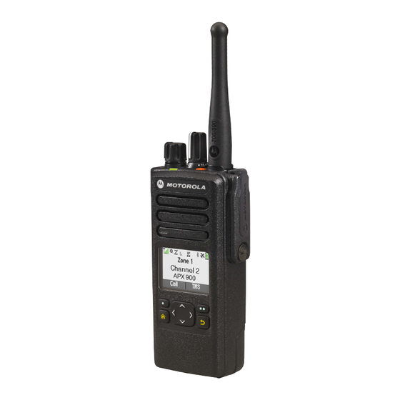
Page 19: Chapter 3: Radio Controls
MN003110A01-AU Chapter 3: Radio Controls Chapter 3 Radio Controls This chapter explains the buttons and functions to control the radio. Radio Parts and Controls 16-Position Select Knob This knob is usually programmed for channel selection. On/Off/Volume Control Knob Rotate clockwise until you hear a click to turn on the radio. Rotate counterclockwise until you hear a click to turn off the radio. -
Page 20: Programmable Features
MN003110A01-AU Chapter 3: Radio Controls Rotate counterclockwise to decrease the volume. LED Indicator Top Side (Select) Button Use this programmable button to access a programmed function or enable or disable a feature. Microphone Push-to-Talk (PTT) Button Press and hold to talk in simplex calls or to initiate a group call, release it to listen. Side Button 1 Use this programmable button to access a programmed function or enable or disable a feature. - Page 21 MN003110A01-AU Chapter 3: Radio Controls Bluetooth Configuration Allows you to access the Bluetooth menu. Bluetooth Audio Reroute Toggles the audio route between the radio speaker or the Remote Speaker Microphone and the Bluetooth headset. Bluetooth Headset PTT Keys up the Bluetooth Headset microphone. Bluetooth Data Devices Pairs your radio with other data devices for data transfer.
- Page 22 MN003110A01-AU Chapter 3: Radio Controls Nuisance Delete Temporarily removes an unwanted channel, except for priority channels and the designated transmit channel from the scan list. Phone Call Allows you to make and receive calls similar to standard phone calls. Private Call (Trunking Only) Allows a call from one individual radio to another.
-
Page 23: Assignable Settings Or Utility Functions
MN003110A01-AU Chapter 3: Radio Controls Talkaround/Direct (Conventional Only) Toggles between using a repeater or communicating directly with another radio. Talkgroup (Conventional Only) Initiates a call to a preprogrammed group of radios. Text Messaging Service (TMS) Allows you to access the Text Messaging Service (TMS) menu. TMS Quick Text Selects a predefined message. -
Page 24: Chapter 4: Status Indicators
MN003110A01-AU Chapter 4: Status Indicators Chapter 4 Status Indicators This section explains the status indicators of the radio. Battery Charge Status Your radio indicates the battery charge status through LED, sounds, and the battery icon on the display. You can also check the battery charge status by using the menu entry. Battery Protection is activated when the battery is low or operating in extremely low temperatures to extend radio communication. -
Page 25: Accessing The Battery Info Screen
MN003110A01-AU Chapter 4: Status Indicators 4.1.2 Accessing the Battery Info Screen This feature displays the current capacity and charges cycles of your battery when an IMPRES battery is powering your radio. This feature must be enabled in your radio to see the information. Procedure: to Batt. -
Page 26: Status Icons
MN003110A01-AU Chapter 4: Status Indicators Table 1: LED Indications Indication Status Solid red Radio is transmitting. Blinking red Radio is transmitting at low battery condition. Double blinking red Radio is transmitting an emergency alarm or call. Rapid blinking red Radio has failed the self-test upon powering up or encountered a fatal error. Solid yellow Radio is receiving in both trunking and conventional clear mode. - Page 27 MN003110A01-AU Chapter 4: Status Indicators Icon Description The radio is connected with other radios through a repeater. The selected channel is being monitored in conventional operation. The In-Call User Alert feature is enabled. Voice muting of the affiliated trunking talkgroup or selected conventional channel is activated. The radio is set at High power.
-
Page 28: Tms Status Icons
MN003110A01-AU Chapter 4: Status Indicators Icon Description The Bluetooth wireless technology is turned on and ready for connection. Steady Bluetooth is connected to the external Bluetooth device. Blinking Bluetooth device is disconnected. Turn the Multi-Function Knob to turn the volume up or down. TMS Status Icons This feature only supports Model 3.5 and Model 2.5. -
Page 29: Alert Tones
MN003110A01-AU Chapter 4: Status Indicators Call icons appear on the radio display when you make or receive a call, or view selected call lists. The call icons indicate the call types associated with an alias or ID. Table 3: Call Type Icons Icon Description A radio number. - Page 30 MN003110A01-AU Chapter 4: Status Indicators You Hear Tone Name Heard Talk Prohibit/PTT Inhibit (When PTT button is pressed) transmissions are not al- lowed. Lack of Voice PTT Time When the radio ends your call after it detected there is lack of voice for 60 seconds after the PTT is pressed and hold.
- Page 31 MN003110A01-AU Chapter 4: Status Indicators You Hear Tone Name Heard Gurgle Dynamic Regrouping (When PTT button is pressed) a dynamic ID has been received. Talk Permit (When PTT button is pressed) is verifying with the system for accepting its transmissions. Unique, New Message When a new message is received.
- Page 32 MN003110A01-AU Chapter 4: Status Indicators You Hear Tone Name Heard Short, Medi- Valid Key-Press When a correct key is pressed. um-Pitched Radio Self Test Pass When radio passes its power-up self test. Tone Clear Voice At beginning of a non-coded communication. Priority Channel Re- When activity on a priority channel is received.
-
Page 33: Phone Call Displays And Alerts
MN003110A01-AU Chapter 4: Status Indicators Phone Call Displays and Alerts The following phone call displays and alerts appears on the radio display when you make and receive phone calls. The radio also uses alert tones to indicate the current status. You Hear You See When... -
Page 34: Chapter 5: General Radio Operation
MN003110A01-AU Chapter 5: General Radio Operation Chapter 5 General Radio Operation This chapter explains the general operations of your radio. Selecting a Zone When and where to use: A zone is a group of channels. Do one of the following to select a radio channel. You can use these options interchangeably depending on your preference and the programmed functions. -
Page 35: Mode Select Feature
MN003110A01-AU Chapter 5: General Radio Operation Positions of ChUp and ChDn on the display may differ each time you release the Menu Select button. Read carefully before you press. Mode Select Feature The Mode Select feature allows you to save the current zone and channel on your radio to one of the Mode Select feature menus (MS01–MS05) on a programmable side button (MS01–MS13). -
Page 36: Receiving And Responding To A Radio Call
MN003110A01-AU Chapter 5: General Radio Operation Receiving and Responding to a Radio Call Once you have selected the required channel and/or zone, you can proceed to receive and respond to calls. The radio shows different indicators based on the system the radio is configured. ●... -
Page 37: Receiving And Responding To A Telephone Call (Trunking Only)
MN003110A01-AU Chapter 5: General Radio Operation 3. Press or the Call Response button to hang up and return to the Home screen. Result: 5.4.3 Receiving and Responding to a Telephone Call (Trunking Only) This feature allows you to receive calls similar to standard phone calls from a landline phone. When and where to use: When you receive a Telephone Call, you hear a telephone-type ringing and the LED blinks green. -
Page 38: Making A Private Call (Trunking Only)
MN003110A01-AU Chapter 5: General Radio Operation 5.5.2 Making a Private Call (Trunking Only) When and where to use: This feature allows you to send an individual Call Alert or page if there is no answer from the target radio. Procedure: to Call , and press the Menu Select button directly below Call . -
Page 39: Making A Telephone Call (Trunking Only)
MN003110A01-AU Chapter 5: General Radio Operation If no acknowledgment is received, the display shows No acknowledge. If the target radio does not respond before the time out, the display shows No answer. 5. Press and hold the PTT button to talk. Release the PTT button to listen. 6. -
Page 40: Monitoring A Channel
MN003110A01-AU Chapter 5: General Radio Operation The lack of static on a digital channel when you switch from analog to digital radios is not an indication that the radio is malfunctioning. Digital technology quiets the transmission by removing the noise from the signal and allows only the clear voice or data information to be heard. -
Page 41: Chapter 6: Additional Performance Enhancement
MN003110A01-AU Chapter 6: Additional Performance Enhancement Chapter 6 Additional Performance Enhancement The following performance enhancements are some of the latest creations designed to enhance the security, quality, and efficiency of the radios. ASTRO 25 Enhanced Data ASTRO 25 Enhanced Data is optimized to handle different message sizes and variable update rates from different applications of the radio. -
Page 42: P25 Digital Vehicular Repeater System
Chapter 6: Additional Performance Enhancement P25 Digital Vehicular Repeater System Motorola Solutions offers an MSI Certified APX compatible, third party, P25 Digital Vehicular Repeater System (DVRS). This provides low-cost portable radio coverage in areas where only mobile radio coverage is available. -
Page 43: Chapter 7: Advanced Features
MN003110A01-AU Chapter 7: Advanced Features Chapter 7 Advanced Features This chapter explains the operations of the features available in your radio. Advanced Call Features This chapter explains the operations of the call features available in your radio. 7.1.1 Selective Call (ASTRO Conventional Only) A Selective Call is a call from an individual radio to another individual radio with privacy. -
Page 44: Talkgroup Call Feature (Conventional Only)
MN003110A01-AU Chapter 7: Advanced Features The display shows the ID of the target radio. 5. Release the PTT button to listen. 6. Press to return to the Home screen. 7.1.2 Talkgroup Call Feature (Conventional Only) This feature allows you to define a group of conventional system users so that they can share the use of a conventional channel. -
Page 45: Making Priority Dispatch Calls
MN003110A01-AU Chapter 7: Advanced Features 3. Press the PTT button to send the status. When the dispatcher acknowledges, you hear four tones and the display shows Ack received. The radio returns to normal dispatch operation. If no acknowledgment is received, you hear a low-pitched tone and the display shows No acknowledge. -
Page 46: Classification Of Regrouped Radios
MN003110A01-AU Chapter 7: Advanced Features 7.1.5.1 Classification of Regrouped Radios The dispatcher can classify regrouped radios into Select Enabled or Select Disabled categories. Select Enabled Select-enabled radios are free to change to any available channel, including the dynamic-regrouping channel, once you have selected the dynamic-regrouping position. Select Disabled Select-disabled radios cannot change channels while dynamically regrouped. -
Page 47: Saving A Channel In The Dynamic Zone From List Selection
MN003110A01-AU Chapter 7: Advanced Features 3. Perform one of the following actions: ● Press the Menu Select button below Sel to select. ● Press the Menu Select button below Exit to exit. If you have selected one of the Dynamic Zone Channels list, the display returns to Home screen with the selected <# Dynamic Zone Channels>... -
Page 48: Zone-To-Zone Cloning
MN003110A01-AU Chapter 7: Advanced Features If the channel deleted is the Home channel, the Home screen shows <Zone Name>“Blank”. 7.1.7 Zone-to-Zone Cloning Zone Cloning clones conventional zones from one radio to another. You can select the followings zones from a source radio and clone them into a target radio. ●... -
Page 49: Multiple Private Line
MN003110A01-AU Chapter 7: Advanced Features 7.1.8 Multiple Private Line Multiple Private Line (MPL) is a feature that allows user to modify the PL/DPL codes of the current mode by selecting from a predefined list of codes. For the purpose of accessing different communication sub-groups, repeaters and others, user no longer need to program multiple channels of the same frequency with different PL/DPL codes. -
Page 50: Contacts
MN003110A01-AU Chapter 7: Advanced Features Contacts This feature provides address-book capabilities on your radio. Each entry corresponds to an alias (name) and ID (number) that you use to initiate a call. Contact entries are alphabetically sorted according to the entry alias. -
Page 51: Adding A Contact To A Call List
MN003110A01-AU Chapter 7: Advanced Features If the call reaches the maximum ring time, the call ends. 7.3.2 Adding a Contact to a Call List Procedure: to Cnts and press the Menu Select button directly below Cnts . The entries are alphabetically sorted. to the entry you want to add and press the Menu Select button directly below Optn . -
Page 52: Scan Lists
MN003110A01-AU Chapter 7: Advanced Features to View and press the Menu Select button directly below Sel . Result: The display shows all the numbers associated with the entry. Scan Lists Scan lists are created and assigned to individual channels or groups. Your radio scans for voice activity by cycling through the channel or group. -
Page 53: Changing The Scan List Status
MN003110A01-AU Chapter 7: Advanced Features ● Press the Top Side button to add and/or change the priority of the currently displayed channel in the scan list. ● Press the Menu Select button directly below Del to delete the currently displayed channel from the scan list. -
Page 54: Scan
MN003110A01-AU Chapter 7: Advanced Features ● A Scan icon indicates that the current channel is in the scan list as a non-priority channel. The LED lights up solid green. ● A Priority-One Channel Scan icon indicates that the current channel is in the scan list as the Priority-One channel. -
Page 55: Deleting A Nuisance Channel
MN003110A01-AU Chapter 7: Advanced Features 7.5.3 Deleting a Nuisance Channel When and where to use: If a channel continually generates unwanted calls or noise (termed “nuisance” channel), you can temporarily remove the unwanted channel from the scan list. This capability does not apply to priority channels or the designated transmit channel. Procedure: When the radio is locked onto the channel to be deleted, perform one of the following actions: ●... -
Page 56: Sending A Call Alert Page
MN003110A01-AU Chapter 7: Advanced Features 7.6.2 Sending a Call Alert Page When and where to use: Do one of the following to send a call alert page: NOTE: If the feature inactivity timer is enabled, your radio automatically exits the feature when your radio is left idle long enough for the time to expire. -
Page 57: Viewing Recent Calls
MN003110A01-AU Chapter 7: Advanced Features ● Call Alert ● Selective Call ● Private Call ● Phone Call (Outgoing Only) ● Emergency Call (Incoming Only) NOTE: The Log Dispatch Calls Enable field need to be enabled in Customer Programming Software (CPS) for your radio to log the dispatch call. 7.7.1 Viewing Recent Calls Do one of the following to view recent calls. -
Page 58: Instant Recall
MN003110A01-AU Chapter 7: Advanced Features This feature allows you to delete calls from the Recent Calls list. Procedure: Delete calls by using the following options: Option Actions Deleting all calls a. Press Optn. b. Select Delete Calls. c. Select All Calls. d. -
Page 59: In-Call User Alert
MN003110A01-AU Chapter 7: Advanced Features To return to the previous screen, press the Menu Select button directly below Back. g. To return to the Home screen, press the Menu Select button directly below Exit. Recent calls are lost after radio power cycle if the calls are not saved. ●... -
Page 60: Quik Call Ii
MN003110A01-AU Chapter 7: Advanced Features Voice Mute button-press or the Voice Mute menu-selection allows the radio-user to toggle on and off Voice Mute functionality. Quik Call II This feature allows you to broadcast a series of distinct and recognizable tones before a voice transmission from the dispatcher or a radio. -
Page 61: Special Considerations For Emergency Operation
MN003110A01-AU Chapter 7: Advanced Features Tactical/Non-Revert The radio sends an emergency alarm and/or makes an emergency call on the current channel. Non-Tactical/Revert for Conventional System The radio reverts to the programmed emergency channel to send an alarm and/or make an emergency call. -
Page 62: Exiting Emergency As Supervisor (Trunking Only)
MN003110A01-AU Chapter 7: Advanced Features 7.10.4 Exiting Emergency as Supervisor (Trunking Only) Radios configured as Supervisor are able to cancel emergency mode of other radios. The dispatch console must be preprogrammed to use this feature. For more information, contact your system administrator. Procedure: Perform one of the following actions: If…... -
Page 63: Manually Refreshing The Remote Emergency List
MN003110A01-AU Chapter 7: Advanced Features ● Transmit Inhibit ● Out of Range ● Imbalance Coverage If your radio receives acknowledgment, your radio displays a positive notification. If your radio does not receive acknowledgment from the target radio, your radio displays a negative notification. -
Page 64: Sending An Emergency Call (Trunking Only)
MN003110A01-AU Chapter 7: Advanced Features ● The display shows Emergency and the current zone or channel. You hear a short medium-pitched tone and the LED blinks red momentarily. ● The radio sounds a short low-pitched tone to indicate that the selected channel does not support emergency and rejects to launch emergency mode. -
Page 65: Sending An Emergency Alarm With Emergency Call
MN003110A01-AU Chapter 7: Advanced Features Follow the procedure to send Emergency Call with hot mic on your radio. Procedure: 1. Press the preprogrammed Emergency button. One of the following scenarios occurs: ● The display shows Emergency on the current zone and channel. A tone sounds and the LED blinks red momentarily. -
Page 66: Sending A Silent Emergency Alarm
MN003110A01-AU Chapter 7: Advanced Features Follow the procedure to send Emergency Alarms and Call with hot mic on your radio. Procedure: 1. Press the preprogrammed Emergency button. If successful, the display shows Emergency on the current zone and channel. A tone sounds and the LED blinks red momentarily. -
Page 67: Entering Fireground Zone Channel (Conventional)
MN003110A01-AU Chapter 7: Advanced Features ● Optional Data Radio (Trunking) ● Accountability Server (Trunking) ● DVRS (Optional) If you have a critical situation, you can press the Emergency button, which activates an alarm on the Incident Management Software at the command terminal. The command terminal receives the following status updates from your radio: ●... -
Page 68: Sending Evacuation Tone
MN003110A01-AU Chapter 7: Advanced Features Communication System. The ergonomic (visual and audible) response for the Tactical Alerts can be customized. Your radio sounds the audible response at the profile maximum alert tone volume level. The display shows the configurable programmed alert text and intelligent lighting. Procedure: Perform one of the following actions: ●... -
Page 69: User Login Feature
MN003110A01-AU Chapter 7: Advanced Features a. Once the zone you want is displayed, turn the preprogrammed 16-Position Select knob to the desired mode. ● Selecting or Changing the ARS mode using the radio menu: to Chan . b. Press the Menu Select button directly below Chan . The display shows the current channel name. -
Page 70: Logging Out
MN003110A01-AU Chapter 7: Advanced Features ● In ARS Non-Server Mode, the display shows the User Login Indicator icon, the ID, and Logged in, with Logt and Exit. ● In non-ARS enabled mode, the display shows Offline, with Logt and Exit. Result: One of the following scenarios occurs: ●... -
Page 71: Sending A Quick Text Message
MN003110A01-AU Chapter 7: Advanced Features 7.14.1 Sending a Quick Text Message When and where to use: Quick Text messages are messages that are predefined and usually consist of messages that are used most frequently. Each Quick Text message has a maximum length of 50 characters. You can select the required text from the Quick Text. -
Page 72: Priority Status And Request Reply For New Text Messages
MN003110A01-AU Chapter 7: Advanced Features 7.14.2 Priority Status and Request Reply for New Text Messages Before sending your message, you can add a priority status, request reply, or both to your message. 7.14.2.1 Appending a Priority Status to a Text Message When and where to use: NOTE: The Priority Status icon on a message does not imply that the message gets higher priority over the other messages when it is being transmitted. -
Page 73: Appending A Priority Status And A Reply Request To A Text Message
MN003110A01-AU Chapter 7: Advanced Features 7.14.2.5 Appending a Priority Status and a Reply Request to a Text Message Procedure: 1. Press the Menu Select button directly below Optn . to Mark Important and press the Menu Select button directly below Sel to indicate that the message is important. -
Page 74: Viewing A Text Message From The Inbox
MN003110A01-AU Chapter 7: Advanced Features 7.14.2.8 Viewing a Text Message from the Inbox When and where to use: The Inbox can hold up to 30 messages. NOTE: to read the message if the content fills more than one screen. Procedure: 1. -
Page 75: Sent Text Messages
MN003110A01-AU Chapter 7: Advanced Features to Send Message and press the Menu Select button directly below Sel to send the message. Result: The display shows the Send Message screen and Sending msg. NOTE: Press the Back button at any time to return to the previous screen. You can append a priority status and/or a request reply to your message. -
Page 76: Deleting A Text Message
ASTRO 25 Advanced Messaging Solution The ASTRO 25 Advanced Messaging Solution allows you to quickly send and receive messages and run database queries directly from your data-enabled Motorola Solutions two-way radios. Federal mandate requires Two-Factor Authentication when querying Federal and State databases. -
Page 77: Two-Factor Authentication
MN003110A01-AU Chapter 7: Advanced Features 7.15.1 Two-Factor Authentication This feature allows you to log in and authenticate yourself with a username, unit ID, password, and passcode. The user login feature enables the recipient of your message to identify you as the sender by assigning a username to your message. -
Page 78: Logging Out Of Two-Factor Authentication
MN003110A01-AU Chapter 7: Advanced Features ● Press and hold to scroll through the list of predefined Unit IDs at a fast scroll rate. Press the Menu Select button directly below Sel to select the predefined Unit ID. If the selected predefined Unit ID has more than the maximum allowed characters, or an invalid character in it, the display shows momentary Invalid UnitID. -
Page 79: Receiving A Query
MN003110A01-AU Chapter 7: Advanced Features You shall receive a service advertisement message to indicate the Query is available after you have successfully logged in the radio with a Two-Factor Authentication. NOTE: The query server must be selected as the destination so that it can receive the query message and respond the query with text message. -
Page 80: Secure Operations
MN003110A01-AU Chapter 7: Advanced Features When you receive a query, you hear a unique, high-pitched chirp and the display shows the message icon flagged with “Priority”. The display shows momentary New msg. Procedure: To access the Inbox, press and hold the Data Feature button or the preprogrammed TMS Feature button or press the Menu Select button directly below TMS. -
Page 81: Managing Encryption
MN003110A01-AU Chapter 7: Advanced Features 7.16.3 Managing Encryption This chapter explains the encryption feature on your radio. 7.16.3.1 Loading Encryption Keys Prerequisites: ● Refer to the Key Variable Loader (KVL) manual for equipment connections and setup. Procedure: 1. Attach the KVL to your radio. The display shows Keyloading and all other radio functions, except for power down, backlight, and volume, are locked out. -
Page 82: Selecting Keysets
MN003110A01-AU Chapter 7: Advanced Features 4. Perform one of the following actions: ● Press the Menu Select button directly below Sel to save the newly selected key and return to the Home screen. ● Press , the PTT button, or the Menu Select button directly below Exit. NOTE: When the selected key is erased, you hear a momentary keyfail tone and the display shows Key fail. -
Page 83: Infinite Ukek Retention
MN003110A01-AU Chapter 7: Advanced Features e. Select Erase all keys? or Erase single key? by pressing the Menu Select button below Yes to erase the encryption key(s) in the radio. You can return to the previous screen by pressing the Menu Select button below No. 7.16.3.6 Infinite UKEK Retention This feature enables Unique Key Encryption Key (UKEK) to be permanently stored in the radio even when all... -
Page 84: Location
MN003110A01-AU Chapter 7: Advanced Features 7.18 Location The Global Navigation Satellite System (GNSS) in the radio integrates information from the Global Positioning System (GPS) to determine the approximate geographical location of your radio. NOTE: The Location feature is addressed as Global Positioning System (GPS) across the manual as the naming convention of the buttons and strings remain the same as the legacy feature of GPS. -
Page 85: Mgrs Coordinates
MN003110A01-AU Chapter 7: Advanced Features The following GPS location formats are available: ● Lat/Long (DD) ● Lat/Long (DDM) ● Lat/Long (DMS) ● UTM/UCS ● SLD99 ● MGRS NOTE: When you send your location to another radio, the receiving radio displays the location in its selected format. -
Page 86: Selecting Location Format
MN003110A01-AU Chapter 7: Advanced Features If the radio fails to get a location fix, the display shows No service and returns to the previous display. 5. To return to the Home screen, press , the PTT button, the preprogrammed GPS button or the Back button. -
Page 87: Viewing A Saved Waypoint
MN003110A01-AU Chapter 7: Advanced Features 7.18.7 Viewing a Saved Waypoint Prerequisites: Ensure your radio shows the current location on the screen. Procedure: 1. Press the Menu Select button directly below Optn. to Waypoints and press the Menu Select button directly below Sel. The display shows a list of waypoints. -
Page 88: Measuring The Distance And Bearing From A Saved Waypoint
MN003110A01-AU Chapter 7: Advanced Features When and where to use: NOTE: You cannot delete any of the preprogrammed waypoints. Procedure: 1. Press the Menu Select button directly below Optn. to Waypoints and press the Menu Select button directly below Sel . The display shows a list of waypoints. -
Page 89: Mission Critical Geofence (Astro 25 Trunking)
MN003110A01-AU Chapter 7: Advanced Features 7.19 Mission Critical Geofence (ASTRO 25 Trunking) This feature allows your radio to use the Global Positioning System (GPS) receiver to determine its location at frequent intervals, and evaluate if the radio is within the Geofence area in real time. Geofence is a virtual perimeter based on the GPS to define a geographical area on earth. -
Page 90: Mission Critical Geofence
MN003110A01-AU Chapter 7: Advanced Features When the radio exits the Geofence area, your radio reverts to original channel or newly assigned talkgroup. The radio display shows the new channel together with Voice Announcement to indicate the changes. Voice Announcement of the new channel only works if that channel is configured with Voice Announcement. 7.19.2 Mission Critical Geofence This feature allows the radio to use the GPS receiver to determine radio location at frequent intervals and... -
Page 91: Imbalanced Coverage
MN003110A01-AU Chapter 7: Advanced Features During failsoft operation, your radio transmits and receives in conventional operation on a predetermined frequency. You hear a medium-pitched tone and the display shows Failsoft. When the trunking system returns to normal operation, your radio automatically leaves failsoft operation and returns to trunked operation. -
Page 92: Viewing The Current Site
MN003110A01-AU Chapter 7: Advanced Features You can toggle the lock state between locked and unlocked by pressing the preprogrammed Site Lock/ Unlock button. Follow the procedure to lock and unlock a site using the radio menu. Procedure: to Site. 2. Press the Menu Select button directly below Site. 3. -
Page 93: Pin Authentication In Pairing
MN003110A01-AU Chapter 7: Advanced Features ● Personal Area Networking (PAN) ● Serial Port (SPP) ● General Attribute Profile (GATT) 7.21.1 PIN Authentication in Pairing This feature allows your radio to verify the correct device to pair with using PIN authentication. NOTE: The PIN authentication method is only applicable for Bluetooth version 2.1 and above. -
Page 94: Pairing The Authentication Pin With The Generated Numeric Pin
MN003110A01-AU Chapter 7: Advanced Features If the PIN is correct but the profiles are not supported, the display shows BT profiles not supported. The display returns to Home screen. 7.21.1.2 Pairing the Authentication PIN with the Generated Numeric PIN Prerequisites: Follow the procedure in Searching and Pairing the Bluetooth Device to search for available Bluetooth devices. -
Page 95: Astro 25 (P25) Programming Over Project 25 (Pop25)
MN003110A01-AU Chapter 7: Advanced Features ● To clear the device from the list, to the required device, press the Menu Select button directly below Clr. ● To exit from this function, press the Menu Select button directly below Back to return to the previous screen without deleting the device name. -
Page 96: Voice Announcement
MN003110A01-AU Chapter 7: Advanced Features upgrade, the process only takes a few seconds. In the case of firmware upgrade, the installation takes several minutes. NOTE: The radio cannot be used while the upgrade is being installed. Therefore, make sure to only accept the upgrade at a convenient time when immediate radio use is not required. -
Page 97: Sending Ssa Notification To All Sites
MN003110A01-AU Chapter 7: Advanced Features to Start Alert and press the Menu Select button directly below Sel. The display shows the Select Site screen. to the desired Site Alias. Press the Menu Select button directly below Sel. The display shows the Select Alert screen. to select the desired Alert Alias and press the Menu Select button directly below Send. -
Page 98: Sending Ssa Notification To All Available Sites
MN003110A01-AU Chapter 7: Advanced Features 7.24.3 Sending SSA Notification to All Available Sites Procedure: to SSA. 2. Press the Menu Select button directly below SSA. The display shows the Site Alert screen. to Start Alert and press the Menu Select button directly below Sel. The display shows the Select Site screen. -
Page 99: Stopping Ssa Notification Of All Sites
MN003110A01-AU Chapter 7: Advanced Features 7.24.5 Stopping SSA Notification of All Sites Procedure: to SSA. 2. Press the Menu Select button directly below SSA. The display shows the Site Alert screen. to Stop Alert and press the Menu Select button directly below Sel. The display shows the Select Site screen. -
Page 100: Utilities
MN003110A01-AU Chapter 7: Advanced Features 7.25 Utilities This chapter explains the operations of the utility functions available in your radio. 7.25.1 Selecting the Power Level This feature enables you to select the power level at which your radio transmits. The radio always turns on to the default setting. -
Page 101: Enabling And Disabling The Radio Alias
MN003110A01-AU Chapter 7: Advanced Features to Prfl and press the Menu Select button directly below Prfl to access the Profiles feature screen. to scroll through the menu selections. c. Press the Menu Select button directly below Sel to select the required radio profile, or press the Menu Select button directly below Exit to exit the screen without making any changes. -
Page 102: Controlling The Display Backlight
MN003110A01-AU Chapter 7: Advanced Features to scroll through the menu selections. d. Press the Menu Select button directly below Sel to select the radio profile with the required speaker routing or press the Menu Select button directly below Exit to exit the screen without making any changes. -
Page 103: Turning Voice Mute On Or Off
MN003110A01-AU Chapter 7: Advanced Features to Mute. b. Press the Menu Select button directly below Mute. The display shows momentary Tones off, indicating that the tones are disabled or the display shows momentary Tones on, and you hear a short tone indicating that the tones are enabled. 7.25.8 Turning Voice Mute On or Off This feature allows you to mute the voice transmission of the current zone and channel. -
Page 104: Adjusting The Squelch Level
MN003110A01-AU Chapter 7: Advanced Features 7.25.10 Adjusting the Squelch Level The Adjustable Fine Tune Squelch feature allows you to adjust the desired squelch level of the radio between level 0 and 15. The following settings determine the types of call that you receive: ●... -
Page 105: Using Conventional Squelch Operation Features
MN003110A01-AU Chapter 7: Advanced Features 7.25.11.1 Using Conventional Squelch Operation Features Procedure: to Sql. 2. Press the Menu Select button directly below Sql. The display shows Squelch XX, where XX is the value for the current squelch. 3. Perform one of the following actions: ●... -
Page 106: Transmit Inhibit
MN003110A01-AU Chapter 7: Advanced Features Mode Description Transmit Inhibit on Busy Channel with Carrier You cannot transmit if traffic is detected on the channel. Transmit Inhibit on Busy Channel with Wrong You cannot transmit on an active channel with a Squelch Code squelch code or (if secure-equipped) encryption key other than your own. -
Page 107: Disabling Transmit Inhibition
MN003110A01-AU Chapter 7: Advanced Features 7.25.15.2 Disabling Transmit Inhibition Procedure: Perform one of the following actions: ● to TxIn. Press the Menu Select button below TxIn. ● Press the Transmit Inhibit programmable button. NOTE: If the user has disabled TX Inhibit using the softkey and then moves the switch to the position where TX Inhibit is enabled, the new value overwrites the menu value. -
Page 108: Viewing The Ip Information
MN003110A01-AU Chapter 7: Advanced Features ● Option Board Serial Number (optional) ● Option Board Software Version (optional) ● Language Pack ID and Version (only when the language of the display is set to non-English) ● Codeplug Alias (Optional) NOTE: To return to the Home screen, press at any time. -
Page 109: Front Panel Programming
MN003110A01-AU Chapter 7: Advanced Features Programmable Features on page 20 for more information on the various programmable features of your radio. Procedure: 1. Perform one of the following actions: ● Press the preprogrammed Info button. ● to Info and press the Menu Select button directly below Info. to Control map and press the Menu Select button directly below Sel. -
Page 110: Changing Password (Optional)
The radio displays Radio Param and Zn/Ch Param. 7.25.17.2 Changing Password (Optional) Radios from the Motorola Solutions factory are provisioned with a blank password. Prerequisites: To access the protected channels, press OK when the Enter Old Password prompts you to change the password. -
Page 111: Editing Parameters
MN003110A01-AU Chapter 7: Advanced Features 2. Enter the password and press the Menu Select button directly below Ok. to scroll through the various information. 4. Press EDIT to edit the channel parameter. 5. Change the parameter value. 6. Press OK to accept the parameter change and return to view mode. 7. - Page 112 MN003110A01-AU Chapter 7: Advanced Features Parameter Editing Keys Value Tx Deviation 5.0 kHz/4.0 kHz/2.5 kHz Power Level High/Low Hot Keypad ON/OFF Busy LED ON/OFF Low Batt LED ON/OFF MPL Enable Disabled/Rx/T x/All Scan List None/Scan List 1, 2, 3,... Zone Name The names must be configured in CPS.
-
Page 113: Chapter 8: Accessories
MN003110A01-AU Chapter 8: Accessories Chapter 8 Accessories Not all accessories are FCC certified to operate with all radio models, band splits, or both. See the radio price pages for a list of FCC certified accessories or contact your sales representative for accessory compatibility. https://www.motorolasolutions.com to know more about the accessories supported by this radio. -
Page 114: Legal And Compliance Statements
Furthermore, Motorola Solutions reserves the right to change any products to improve readability, function, or design. Motorola Solutions does not assume any liability arising out of the applications or use of any product or circuit described herein; nor does it cover any license under its patent rights, nor the rights of others. -
Page 115: Important Safety Information
(e.i.r.p.) is not more than that necessary for successful communication. This radio transmitter is approved by ISED to operate with a Motorola Solutions-approved antenna with the maximum permissible gain and required antenna impedance for each antenna type indicated. Antenna types not included in this list, having a gain greater than the maximum gain indicated for that type, are strictly prohibited for use with this device. -
Page 116: Fcc Licensing Information
Applying for Canadian License The operation of your Motorola Solutions radio is subject to the Radio communications Act and must comply with rules and regulations of the Federal Government's department of Innovation, Science, and Economic Development Canada (ISED). -
Page 117: Maritime Radio Use In The Vhf Frequency Range
MN003110A01-AU Maritime Radio Use in the VHF Frequency Range Maritime Radio Use in the VHF Frequency Range Special Channel Assignments Emergency Channel If you are in imminent and grave danger at sea and require emergency assistance, use VHF Channel 16 to send a distress call to nearby vessels and the United States Coast Guard. -
Page 118: Table 7: Vhf Marine Channel List
MN003110A01-AU Maritime Radio Use in the VHF Frequency Range ○ in the simplex mode on the ship station transmitting frequencies specified in the 156.025–157.425 MHz frequency band, and ○ in the semiduplex mode on the two frequency channels specified in the table below. NOTE: Simplex channels 3, 21, 23, 61, 64, 81, 82, and 83 cannot be lawfully used by the general public in US waters. - Page 119 MN003110A01-AU Maritime Radio Use in the VHF Frequency Range 157.400 162.000 156.025 160.625 156.075 160.675 156.125 160.725 156.175 160.775 156.225 160.825 156.275 160.875 156.325 160.925 67** 156.375 156.375 156.425 156.425 156.475 156.475 156.575 156.575 156.625 – 156.675 156.675 156.725 156.725 77** 156.875 –...
-
Page 120: Declaration Of Compliance For The Use Of Distress And Safety Frequencies
MN003110A01-AU Maritime Radio Use in the VHF Frequency Range Declaration of Compliance for the Use of Distress and Safety Frequencies The radio equipment does not employ a modulation other than the internationally adopted modulation for maritime use when it operates on the distress and safety frequencies specified in RSS-182 Section 5.4. Technical Parameters for Interfacing External Data Sources RS232... -
Page 121: Limited Warranty
Product Accessories One (1) Year MOTOROLA SOLUTIONS, at its option, will at no charge either repair the Product (with new or reconditioned parts), replace it (with a new or reconditioned Product), or refund the purchase price of the Product during the warranty period provided it is returned in accordance with the terms of this warranty. -
Page 122: Ii. General Provisions
MN003110A01-AU Limited Warranty in the terms and conditions. Repairs will be made only at the designated MOTOROLA SOLUTIONS repair depot. Local services are not included. MOTOROLA SOLUTIONS will pay the inbound shipping charges only with use of the MOTOROLA SOLUTIONS designated delivery service. MOTOROLA SOLUTIONS will pay for outbound shipping via MOTOROLA SOLUTIONS'S normal shipping methods. -
Page 123: Vi. Patent And Software Provisions
1. that MOTOROLA SOLUTIONS will be notified promptly in writing by such purchaser of any notice of such claim, 2. -
Page 124: Vii. Governing Law
This provision applies to products and services supplied by Motorola Solutions to consumers within the meaning of the Australian Consumer Law. This warranty is given by Motorola Solutions Australia Pty Limited (ABN16 004 742 312) of Tally Ho Business Park, 10 Wesley Court. Burwood East, Victoria. Our goods come with guarantees that cannot be excluded under the Australia Consumer Law.
Need help?
Do you have a question about the APX 900 2 and is the answer not in the manual?
Questions and answers