
Subscribe to Our Youtube Channel
Related Manuals for Motorola solutions APX N50 2


Summary of Contents for Motorola solutions APX N50 2
- Page 1 ™ Two-Way Radios Model 2 APX N50 User Guide *MN009203A01* OCTOBER 2024 MN009203A01-AG © 2024 Motorola Solutions, Inc. All Rights Reserved.
-
Page 2: Table Of Contents
Declaration of Compliance for the Use of Distress and Safety Frequencies....17 Technical Parameters for Interfacing External Data Sources...........17 Limited Warranty............................ 17 MOTOROLA SOLUTIONS COMMUNICATION PRODUCTS.............17 I. WHAT THIS WARRANTY COVERS AND FOR HOW LONG:..........17 II. GENERAL PROVISIONS:.......................18 III. STATE LAW RIGHTS:......................18 IV. - Page 3 MN009203A01-AG Contents 2.1 Keypad Overview..........................25 2.2 Programmable Radio Functions...................... 26 2.3 ViQi..............................29 2.3.1 Activating Basic Voice Control................... 31 2.3.2 Using ViQi Virtual Partner....................31 Chapter 3: Getting Started....................32 3.1 Attaching and Removing the Battery....................32 Attaching the Battery........................32 Removing the Battery........................32 3.2 Attaching and Removing the Antenna.....................
- Page 4 MN009203A01-AG Contents 5.8 Editing the Time and Date........................44 5.9 Locking and Unlocking the Controls....................44 5.10 Setting the Tones for Controls and Buttons .................. 45 5.11 Setting the Voice Mute........................45 5.12 Using the Time-Out Timer......................45 5.13 Adjusting the Squelch Level......................46 5.14 Conventional Squelch Operation....................
- Page 5 MN009203A01-AG Contents 8.7.1 Sending Emergency Beacons....................58 8.7.2 Receiving Emergency Beacons..................58 8.7.3 Viewing Received Emergency Beacon................58 Chapter 9: Fireground......................59 9.1 Entering Fireground Zone Channel (Conventional)................. 59 9.2 Responding to Evacuation Indicator....................60 9.3 Sending Evacuation Tone........................ 60 Chapter 10: Tactical Public Safety (Conventional Only)..........61 10.1 Using TPS Normal Transmission....................
- Page 6 MN009203A01-AG Contents 15.3 Bluetooth ® ............................72 15.3.1 Turning Bluetooth On or Off..................... 73 15.3.2 Searching and Pairing the Bluetooth Device..............73 15.3.3 Turning Bluetooth Audio On or Off................... 73 15.3.4 Viewing and Clearing the Bluetooth Enabled Device Information........73 15.4 ASTRO 25 (P25) Programming Over Project 25 (POP25)............74 15.4.1 Responding to Upgrade Notifications................74 Chapter 16: Location ......................75 16.1 Turning Location On or Off......................75...
- Page 7 MN009203A01-AG Contents Chapter 25: Monitor Feature..................... 92 25.1 Monitoring Channels........................92 25.2 Monitoring Conventional Mode...................... 92 Chapter 26: Remote Monitor..................... 94 Chapter 27: Transmit Inhibit....................95 27.1 Enabling or Disabling Transmit Inhibit....................95 27.2 Smart PTT (Conventional Only).....................95 Chapter 28: Dynamic Regrouping (Trunking Only) ............97 28.1 Classification of Regrouped Radios....................97 28.2 Requesting a Reprogram (Trunking Only)..................
-
Page 8: List Of Figures
MN009203A01-AG List of Figures List of Figures Figure 1: Radio Overview..........................24 Figure 2: Keypad Overview..........................25 Figure 3: Home Screen Display........................35... -
Page 9: List Of Tables
MN009203A01-AG List of Tables List of Tables Table 1: VHF Marine Channel List........................15 Table 2: Radio Overview Description........................24 Table 3: Keypad Overview..........................26 Table 4: Assignable Radio Functions........................26 Table 5: ViQi Basic Voice Control Commands....................29 Table 6: ViQi Virtual Partner Queries........................ 30 Table 7: Home Screen Overview Description.................... -
Page 10: Legal And Support
License Rights The purchase of Motorola Solutions products shall not be deemed to grant either directly or by implication, estoppel or otherwise, any license under the copyrights, patents or patent applications of Motorola Solutions, except for the normal nonexclusive, royalty-free license to use that arises by operation of law in the sale of a product. -
Page 11: Legal And Compliance Statements
Furthermore, Motorola Solutions reserves the right to change any products to improve readability, function, or design. Motorola Solutions does not assume any liability arising out of the applications or use of any product or circuit described herein; nor does it cover any license under its patent rights, nor the rights of others. -
Page 12: Ised Wlan Statement
Before using the radio, read the RF Energy Exposure and Product Safety Guide for Portable Two- Way Radios which contains important operating instructions for safe usage and RF energy awareness and control for Compliance with applicable standards and Regulations. For a list of Motorola Solutions-approved antennas, batteries, and other accessories, visit the following website: https://www.motorolasolutions.com... -
Page 13: Notice To Users (Fcc)
MN009203A01-AG Legal and Support Any modification to this device, not expressly authorized by Motorola Solutions, may void your authority to operate this device. Under Innovation, Science, and Economic Development Canada (ISED) regulations, this radio transmitter may only operate using an antenna of a type and maximum (or lesser) gain approved for the transmitter by ISED. -
Page 14: Applying For Canadian License
Legal and Support Applying for Canadian License The operation of your Motorola Solutions radio is subject to the Radio communications Act and must comply with rules and regulations of the Federal Government's department of Innovation, Science, and Economic Development Canada (ISED). ISED requires that all operators using Private Land Mobile frequencies obtain a radio license before operating their equipment. -
Page 15: Non-Commercial Call Channel
MN009203A01-AG Legal and Support 11. If you do not receive an immediate response, remain by the radio, and repeat the transmission at intervals until you receive a response. Be prepared to follow any instructions given to you. Non-Commercial Call Channel For non-commercial transmissions, such as fishing reports, rendezvous arrangements, repair scheduling, or berthing information, use VHF Channel 9. - Page 16 MN009203A01-AG Legal and Support 17** 156.850 156.850 156.900 161.500 156.950 161.550 157.000 161.600 157.050 161.650 157.100 161.700 157.150 161.750 157.200 161.800 157.250 161.850 157.300 161.900 157.350 161.950 157.400 162.000 156.025 160.625 156.075 160.675 156.125 160.725 156.175 160.775 156.225 160.825 156.275 160.875 156.325 160.925...
-
Page 17: Declaration Of Compliance For The Use Of Distress And Safety Frequencies
Product Accessories One (1) Year MOTOROLA SOLUTIONS, at its option, will at no charge either repair the Product (with new or reconditioned parts), replace it (with a new or reconditioned Product), or refund the purchase price of the Product during... -
Page 18: Ii. General Provisions
MOTOROLA SOLUTIONS cannot be responsible in any way for any ancillary equipment not furnished by MOTOROLA SOLUTIONS which is attached to or used in connection with the Product, or for operation of the Product with any ancillary equipment, and all such equipment is expressly excluded from this warranty. -
Page 19: Iv. How To Get Warranty Service
1. that MOTOROLA SOLUTIONS will be notified promptly in writing by such purchaser of any notice of such claim, 2. -
Page 20: Vii. Governing Law
MN009203A01-AG Legal and Support 3. should the Product or parts become, or in MOTOROLA SOLUTIONS’ opinion be likely to become, the subject of a claim of infringement of a United States patent, that such purchaser will permit MOTOROLA SOLUTIONS, at its option and expense, either to procure for such purchaser the right to continue using the Product or parts or to replace or modify the same so that it becomes non-infringing or to grant such purchaser a credit for the Product or parts as depreciated and accept its return. -
Page 21: Read Me First
MN009203A01-AG Read Me First Read Me First This User Guide covers the basic operation of the radio. Notations Used in This Manual Notations such as Warning, Caution, and Notice are used throughout the text in this publication. These notations are used to emphasize that safety hazards exist, and the care that must be taken or observed. WARNING: An operational procedure, practice, or condition, and so on, which can result in injury or death if not carefully observed. -
Page 22: Chapter 1: Radio Care
MN009203A01-AG Chapter 1: Radio Care Chapter 1 Radio Care Proper radio usage and care ensure efficient operation and long life of the product. CAUTION: Use the radio according to the following recommendations and warnings. ● Never obstruct or cover the vent port, even with a label. ●... -
Page 23: Cleaning Your Radio
Through its maintenance and installation program, Motorola Solutions makes the finest service available to those desiring reliable continuous communications on a contract basis. For a contract service agreement, contact your nearest Motorola Solutions service or sales representative, or an authorized Motorola Solutions dealer. -
Page 24: Chapter 2: Radio Overview
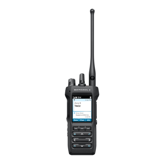
MN009203A01-AG Chapter 2: Radio Overview Chapter 2 Radio Overview Figure 1: Radio Overview Table 2: Radio Overview Description Number Name Description Antenna Allows you to transmit and receive electromagnetic waves during transmitting and receiving. Channel Selector knob Allows you to select channel. On/Off/Volume Control knob Allows you to turn on or off the radio, and adjust the volume. -
Page 25: Keypad Overview
MN009203A01-AG Chapter 2: Radio Overview Number Name Description Speaker Outputs tones and audio that are generated by the radio. Keypad Allows menu navigation and interface selection. Display The radio display screen. Digital Mic 2 Allows your voice to be sent when PTT or voice operations are activated. -
Page 26: Programmable Radio Functions
MN009203A01-AG Chapter 2: Radio Overview Table 3: Keypad Overview Number Button Name Description Menu Select buttons Press to access the corresponding menu. Home button Press to return to Home screen. Programmable button 1 (P1) This button is programmable using the Customer Programming Software (CPS). - Page 27 MN009203A01-AG Chapter 2: Radio Overview Function Description Channel Up/Down Allows you to scroll up or down to other channels within the current Zone. Contacts Allows you to access the Contacts menu. Dual Tone Multiple Frequency Allows you to send out DTMF code of the assigned DTMF value. (DTMF) Tone For example, when DTMF Tone 9 is selected, you can send out DTMF Tone 9.
- Page 28 MN009203A01-AG Chapter 2: Radio Overview Function Description mission of voice communication. Otherwise, the radio blocks the transmission and sounds the Talk Prohibit Tone. Priority Dispatch Allows you to call the dispatcher on a different talkgroup. Radio Profiles Allows you to access a set of programmed visual and audio settings of the radio.
-
Page 29: Viqi
MN009203A01-AG Chapter 2: Radio Overview Function Description Voice Mute Allows you to mute the voice transmission of the current zone and channel. Volume Set Tone Sets the volume set tone. ViQi ViQi allows you to manage your radio and perform information lookups using voice commands. This feature is purpose-built for easier access to features. -
Page 30: Table 6: Viqi Virtual Partner Queries
MN009203A01-AG Chapter 2: Radio Overview Feature Examples ● “Go to help” ViQi Virtual Partner ViQi Virtual Partner helps you to look up information such as license plate, driver's license, and Vehicle ID Number (VIN), and she responds with a result to your query. Table 6: ViQi Virtual Partner Queries The following table shows the queries supported by the ViQi Virtual Partner feature and their respective commands. -
Page 31: Activating Basic Voice Control
MN009203A01-AG Chapter 2: Radio Overview 2.3.1 Activating Basic Voice Control Prerequisites: Configure a programmable button for basic voice control. Procedure: 1. Press and hold the programmed Basic Voice Control button. 2. Speak your command into the radio mic. 3. Release the programmed Basic Voice Control button. Result: Basic voice control is activated and the radio operates according to the voice command. -
Page 32: Chapter 3: Getting Started
MN009203A01-AG Chapter 3: Getting Started Chapter 3 Getting Started This section provides instructions to prepare your radio for use. Attaching and Removing the Battery Attaching the Battery Procedure: Slide the battery into the radio frame until the latches click into place. Removing the Battery Procedure: 1. -
Page 33: Attaching And Removing The Accessory Connector Cover
MN009203A01-AG Chapter 3: Getting Started Attaching and Removing the Accessory Connector Cover The accessory connector is on the antenna side of the radio enables you to connect accessories to the radio. NOTE: To ensure proper operation, turn off the radio before connecting an accessory to the radio. To prevent damage to the connector, shield it with the connector cover when not in use. -
Page 34: Charging The Radio
When and where to use: Motorola Solutions-approved battery shipped with your radio is uncharged. Prior to using a new battery, charge it for a minimum of 16 hours to ensure optimum capacity and performance. For a list of Motorola Solutions-authorized batteries and chargers available for use with your radio, see Accessories. -
Page 35: Chapter 4: Home Screen Overview
MN009203A01-AG Chapter 4: Home Screen Overview Chapter 4 Home Screen Overview Figure 3: Home Screen Display Table 7: Home Screen Overview Description Number Name Description Dark Mode Status Bar Dark mode status icons appear in the status bar to provide device status and feature notifications. Bright Mode Status Bar Bright mode status icons appear in the status bar to provide device status and feature notifications. -
Page 36: Status Icons
MN009203A01-AG Chapter 4: Home Screen Overview 4.1.1 Status Icons These icons appear at the status bar to provide device-specific information or status. Table 8: Status Icons Icon Name Description Battery Level Indicates the remaining battery level of the radio. The icon blinks when the battery level drops to 10% or lower. - Page 37 MN009203A01-AG Chapter 4: Home Screen Overview Icon Name Description Call Received The radio received a call. Direct Mode The radio is configured for direct radio-to-radio communication in conventional operation. Global Positioning System GPS is enabled and the signal is available. (GPS) In-Call User Alert The receiving audio turns off.
- Page 38 MN009203A01-AG Chapter 4: Home Screen Overview Icon Name Description Satellite Receiving The radio is receiving a satellite signal. Satellite Transmitting The radio is transmitting a satellite signal. Satellite Receiving and Transmit- The radio is receiving and transmitting satellite sig- ting nals.
-
Page 39: Led Indications
MN009203A01-AG Chapter 4: Home Screen Overview Icon Name Description Blinking The radio is receiving an AES-encrypted voice call. Power Level High The radio is set at high power. Power Level Low The radio is set at low power. Virtual Private Network (VPN) VPN is activated on the radio. -
Page 40: Intelligent Lighting Indicators
MN009203A01-AG Chapter 4: Home Screen Overview 4.1.3 Intelligent Lighting Indicators This feature temporarily changes the color of the Top Light Bar and adds a color bar to the main display screen to help signal that a radio event has occurred. Table 10: Intelligent Lighting Indicators Backlight and Bar Notification... - Page 41 MN009203A01-AG Chapter 4: Home Screen Overview Indicator Light Bar Color Call State Yellow Receiving and Unmuted Voice Transmission Light Blue Out of Range Light Blue Smart Connect Gray Unprogrammed Gray Receiving Frequency Error...
-
Page 42: Chapter 5: General Radio Operation
MN009203A01-AG Chapter 5: General Radio Operation Chapter 5 General Radio Operation This chapter explains the general operations of your radio. Selecting Zones A zone is a group of channels. Procedure: 1. Press the Zone menu item. 2. Select the required zone and press Sel. Selecting Channels A channel is a group of radio characteristics, such as transmit or receive frequency pairs. -
Page 43: Saving Zones And Channels
MN009203A01-AG Chapter 5: General Radio Operation When programmed, pressing the button changes the transmission to the saved zone and channel. When the Preconfigurable Preset Zone and Channel field is enabled, pressing and holding the preferred Mode Select menu saves the current zone and channel to one of the Mode Select menus. The radio displays MS0x is programmed. -
Page 44: Adjusting The Display Backlight
MN009203A01-AG Chapter 5: General Radio Operation Procedure: Enable or disable the radio alias by pressing the MyID menu item. Result: The display shows momentary Radio ID off, and the radio alias disappears from the Home screen or the display shows momentary Radio ID on, and the radio alias appears on the Home screen. Adjusting the Display Backlight You can enable or disable the radio display backlight as needed, if poor light conditions make the display or keypad difficult to read. -
Page 45: Setting The Tones For Controls And Buttons
MN009203A01-AG Chapter 5: General Radio Operation 5.10 Setting the Tones for Controls and Buttons If needed, you can enable or disable the tones of navigation buttons and controls. Procedure: Turn the tones on or off by pressing the Mute menu item. Result: The display shows a notification message indicating if the tones are enabled or disabled. -
Page 46: Adjusting The Squelch Level
MN009203A01-AG Chapter 5: General Radio Operation 5.13 Adjusting the Squelch Level The Adjustable Fine Tune Squelch feature allows you to adjust the desired squelch level of the radio between level 0 and 15. The following settings determine the types of call that you receive: ●... -
Page 47: Setting Conventional Squelch Operation
MN009203A01-AG Chapter 5: General Radio Operation 5.14.1 Setting Conventional Squelch Operation Procedure: 1. Press the Sql menu item. 2. Perform one of the following actions: ● To increase the squelch volume, press +. ● To decrease the squelch volume, press -. 3. -
Page 48: Accessing The General Radio Information
MN009203A01-AG Chapter 5: General Radio Operation 5.17.1 Accessing the General Radio Information Procedure: 1. Press the Info menu item. 2. Perform one of the following actions: ● To view radio information, press Radio Info. ● To view IP information, press IP Info. ●... -
Page 49: Chapter 6: Trunking System Controls
MN009203A01-AG Chapter 6: Trunking System Controls Chapter 6 Trunking System Controls This chapter explains the trunking system control features on your radio. Operating in Failsoft System The failsoft system ensures continuous radio communication during a trunked system failure. If a trunking system fails completely, the radio goes into failsoft operation and automatically switches to its failsoft channel. -
Page 50: Locking Or Unlocking Sites
MN009203A01-AG Chapter 6: Trunking System Controls The Searching site indicator alerts you that your radio is attempting to search for a valid trunked control channel. Locking or Unlocking Sites This feature allows your radio to lock onto a specific site and not roam among wide-area talkgroup sites. This feature must be used with caution because it inhibits roaming to another site in a wide-area system. -
Page 51: Chapter 7: Types Of Radio Calls
MN009203A01-AG Chapter 7: Types of Radio Calls Chapter 7 Types of Radio Calls Your radio can make a Talkgroup, Private, Selective, and Telephone call in conventional and/or trunking mode. Call Type Conventional Trunking Mode SmartConnect Mode Talkgroup Call This feature is a point-to-multipoint call operation. -
Page 52: Receiving Calls
MN009203A01-AG Chapter 7: Types of Radio Calls Option Actions Private Call a. Enter the Contacts page by pressing the Cnts menu item. b. Select the required preprogrammed contact. c. Start the call by pressing the PTT button. d. To end the call, press Exit. Selective Call a. -
Page 53: Making Priority Dispatch Calls
MN009203A01-AG Chapter 7: Types of Radio Calls Option Actions Selective Call For incoming Selective Calls, your radio automatically plays the transmission from the call. a. Respond to the call by pressing and holding the PTT button. b. Speak into the microphone. Telephone Call Perform one of the following actions: ●... -
Page 54: Chapter 8: Emergency Operation
MN009203A01-AG Chapter 8: Emergency Operation Chapter 8 Emergency Operation The Emergency feature is used to indicate a critical situation. An emergency signal overrides any other communication over the selected channel. Your radio supports the following Emergency modes: ● Emergency Alarm ●... -
Page 55: Sending Emergency Alarms
MN009203A01-AG Chapter 8: Emergency Operation Sending Emergency Alarms Procedure: Press the programmed Top (Orange) button. Result: Your radio shows the following indications: ● A positive indicator tone sounds. ● The red LED blinks. ● The display shows Emergency, and the current zone or channel. When you receive acknowledgement from the dispatcher, your radio shows the following indications: ●... -
Page 56: Remote Emergency
MN009203A01-AG Chapter 8: Emergency Operation Procedure: ● To exit the emergency operation, press and hold the programmed Top (Orange) button. ● To exit the emergency operation as supervisor (Trunking only), use one of the following options: Option Actions Exiting Emergency operation initiated by the Perform one of the following actions: Supervisor ○... -
Page 57: Sending Remote Emergency By Entering The User Id
MN009203A01-AG Chapter 8: Emergency Operation 8.5.2 Sending Remote Emergency by Entering the User ID Procedure: 1. Press the programmed Remote Emergency button. 2. Press any digit key. 3. Enter the number of the user ID. 4. To send Remote Emergency, press the PTT button or press Send. Result: If the ID of the target radio is valid, your radio displays sending notification and saves the ID as the last Remote Emergency ID. -
Page 58: Emergency Keep-Alive
MN009203A01-AG Chapter 8: Emergency Operation 2. Press the Fltr menu item button. Result: Your radio displays the filtered call list. Emergency Keep-Alive This feature prevents the radio from being turned off when it is in Emergency mode. If this feature is enabled, you are required to exit Emergency mode before turning off your radio. -
Page 59: Chapter 9: Fireground
MN009203A01-AG Chapter 9: Fireground Chapter 9 Fireground The portable Fireground Communications System is designed for deployment at an incident scene. It consists of central components that provide on-scene and in building radio coverage, and enhanced personnel accountability and monitoring: ● Your APX portable radios ●... -
Page 60: Responding To Evacuation Indicator
MN009203A01-AG Chapter 9: Fireground Responding to Evacuation Indicator When you receive an Evacuation Indicator, the radio shows the following indications: ● A tone sounds. ● The display shows the configurable programmed alert text and intelligent lighting. Procedure: To respond, perform one of the following actions: ●... -
Page 61: Chapter 10: Tactical Public Safety (Conventional Only)
MN009203A01-AG Chapter 10: Tactical Public Safety (Conventional Only) Chapter 10 Tactical Public Safety (Conventional Only) Tactical Public Safety (TPS) enables the member of a group to identify the start and the end of a transmission by displaying the caller name or ID on the radio display. 10.1 Using TPS Normal Transmission Procedure:... -
Page 62: Chapter 11: Fall Alert
MN009203A01-AG Chapter 11: Fall Alert Chapter 11 Fall Alert Fall Alert is a supporting feature of the Emergency operation. The Emergency feature must be programmed for Fall Alert to operate. Your radio activates the Fall Alert feature when it achieves or exceeds a tilt angle threshold or a combination of the angle threshold and radio motion below the motion sensitivity level. -
Page 63: Exiting Fall Alert
MN009203A01-AG Chapter 11: Fall Alert 2. Lay the radio down in a horizontal position. Result: Your radio shows the following indications: ● Alert tone ● The display shows Man-Down. Postrequisites: If Fall Alert is configured but the condition does not trigger the activation of the feature, send the radio to a qualified technician. -
Page 64: Chapter 12: Secure Operations
MN009203A01-AG Chapter 12: Secure Operations Chapter 12 Secure Operations Secure radio operation provides the highest commercially available level of voice security on both trunked and conventional channels. By default, the radio automatically enters the encrypted environment without having to manually select or clear the secure transmission. -
Page 65: Mdc Otar (Conventional Only)
MN009203A01-AG Chapter 12: Secure Operations There are two types of encryption keys: Conventional Multikey The encryption keys are strapped on a one-per-channel basis, through CPS. In addition, you can have operator-selectable keys, operator-selectable keysets, and operator-selectable key erasure. If talkgroups are enabled in conventional, then the encryption keys are strapped to the talkgroups. -
Page 66: Loading Encryption Keys
MN009203A01-AG Chapter 12: Secure Operations 12.2.5 Loading Encryption Keys Procedure: 1. Attach the Key Variable Loader (KVL) to your radio. The display shows Keyloading. All other radio functions are locked, except power down, backlight, and volume. NOTE: If the Multisystem Over-the-Air Rekeying feature is in use, the ASTRO profile name is displayed below Keyloading. -
Page 67: Requesting Over-The-Air Rekey
MN009203A01-AG Chapter 12: Secure Operations 12.2.9 Requesting Over-the-Air Rekey If the Multi-system Over-the-Air Rekeying feature is in use, the rekey request is only for the current selected secure profile. Prerequisites: Ensure that the Unique Key Encryption Key (UKEK) or Unique Shadow Key (USK) is loaded into the radio with the Key Variable Loader (KVL) before the rekey request can be sent. -
Page 68: Chapter 13: Scan
MN009203A01-AG Chapter 13: Scan Chapter 13 Scan This feature allows you to monitor traffic on different channels by scanning a programmed list of channels. Scanning is halted if you initiate a call and resumes when the call has ended. 13.1 Turning Scan On or Off Procedure: Turn scan on or off by pressing the Scan menu item. -
Page 69: Restoring Nuisance Channels
MN009203A01-AG Chapter 13: Scan 13.4 Restoring Nuisance Channels Procedure: To restore the deleted nuisance channel, perform one of the following actions: ● Stop and restart a scan. ● Mode change to another channel, and return to the original channel. ● Turn off the radio and then turn it on again. -
Page 70: Chapter 14: Scan Lists
MN009203A01-AG Chapter 14: Scan Lists Chapter 14 Scan Lists Scan lists are created and assigned to individual channels or groups. Your radio scans for voice activity by cycling through the channel or group. The sequence of scan is as specified in the scan list for the current channel or group. - Page 71 MN009203A01-AG Chapter 14: Scan Lists Option Actions Recalling the next channel in the At the Edit Scan screen, press Rcl. scan list The display auto scrolls to the next channel in the scan list.
-
Page 72: Chapter 15: Connectivity
This feature allows you to extend your radio functionality by connecting to external Bluetooth accessories. Use Motorola Solutions proprietary Operations Critical Wireless (OCW) devices with radios during critical operations. Other Bluetooth devices may or may not perform to the required standard. -
Page 73: Turning Bluetooth On Or Off
MN009203A01-AG Chapter 15: Connectivity 15.3.1 Turning Bluetooth On or Off Procedure: 1. Press the BT menu item. 2. Select Status. 3. Perform one of the following actions: ● To turn on Bluetooth, press On. ● To turn off Bluetooth, press Off. 15.3.2 Searching and Pairing the Bluetooth Device Prerequisites: Ensure that the Bluetooth on your device is turned on and set to Discoverable in order to... -
Page 74: Astro 25 (P25) Programming Over Project 25 (Pop25)
MN009203A01-AG Chapter 15: Connectivity 3. To view the status of devices that are paired or connected, scroll through the list of <Device Friendly Name>. If there are no active Bluetooth devices paired or connected, the display shows No devices. 4. To clear a device from the list, select the required device and press Clr → Yes. 15.4 ASTRO 25 (P25) Programming Over Project 25 (POP25) -
Page 75: Chapter 16: Location
MN009203A01-AG Chapter 16: Location Chapter 16 Location The Global Navigation Satellite System (GNSS) in the radio integrates information from the Global Positioning System (GPS) to determine the approximate geographical location of your radio. NOTE: The Location feature is addressed as Global Positioning System (GPS) across the manual as the naming convention of the buttons and strings remain the same as the legacy feature of GPS. -
Page 76: Selecting Location Formats
MN009203A01-AG Chapter 16: Location ● UTC (Zulu) Time ● Date NOTE: If the location signal is present, the location coordinates are automatically updated every five seconds. If the radio fails to obtain the current location, the display shows No service and returns to the previous screen. -
Page 77: Location Feature In Emergency Mode
MN009203A01-AG Chapter 16: Location 3. Manage waypoints by using the following options: Option Actions Viewing waypoints a. Scroll to the required waypoint from the list. b. Press Optn → View → Sel. The display shows the following information of the selec- ted waypoint: ●... -
Page 78: Mgrs Coordinates
MN009203A01-AG Chapter 16: Location This feature is operable in a Scan Active channel, or Scan Talkback channel. After receiving a voice transmission with GPS coordinates enabled on the receiving radio, the display shows the available full location, or short location coordinates. Full location coordinates ●... -
Page 79: Chapter 17: Mission Critical Geofence (Astro 25 Trunking)
MN009203A01-AG Chapter 17: Mission Critical Geofence (ASTRO 25 Trunking) Chapter 17 Mission Critical Geofence (ASTRO 25 Trunking) This feature allows the radio to use the Global Positioning System (GPS) receiver to determine its location at frequent intervals and evaluate if the radio is within the Geofence area in real time. Geofence is a virtual perimeter based on the GPS to define a geographical area on earth. -
Page 80: Entry To Mission Critical Geofence
MN009203A01-AG Chapter 17: Mission Critical Geofence (ASTRO 25 Trunking) When the radio exits the Geofence area, your radio reverts to original channel or newly assigned talkgroup. The radio display shows the new channel together with Voice Announcement to indicate the changes. Voice Announcement of the new channel only works if that channel is configured with Voice Announcement. -
Page 81: Chapter 18: Contacts
MN009203A01-AG Chapter 18: Contacts Chapter 18 Contacts This feature provides address-book capabilities on your radio. Each entry corresponds to an alias (name) and ID (number) that you use to initiate a call. Contact entries are alphabetically sorted according to the entry alias. -
Page 82: Chapter 19: Recent Calls
MN009203A01-AG Chapter 19: Recent Calls Chapter 19 Recent Calls Recent call menu allows you to view the recent incoming and outgoing call information. You can view the information of the following type of calls: ● Call Alert ● Selective Call ●... - Page 83 MN009203A01-AG Chapter 19: Recent Calls When you have successfully deleted all calls, your display shows All calls deleted and the Recent Calls list is empty. When you have successfully deleted non-emergency calls, your display shows Non-emer calls deleted and the Recent Calls list only contains emergency calls.
-
Page 84: Chapter 20: Sending Status
MN009203A01-AG Chapter 20: Sending Status Chapter 20 Sending Status You can send status messages to the dispatcher. A status transmission makes more efficient use of a channel as compared to a voice transmission. Procedure: 1. Press the programmed Status button. 2. -
Page 85: Chapter 21: Call Alert Paging
MN009203A01-AG Chapter 21: Call Alert Paging Chapter 21 Call Alert Paging This feature allows your radio to work like a pager. If other users are away from their radios or if they are unable to hear their radios, you can send them an individual call alert page. -
Page 86: Receiving Call Alert Page
MN009203A01-AG Chapter 21: Call Alert Paging 21.2 Receiving Call Alert Page When you receive a Call Alert page, your radio shows the following indications: ● A tone sounds. ● The green LED illuminates. ● The display shows Page received. Procedure: Press any button to clear the Call Alert page. -
Page 87: Chapter 22: Automatic Registration Service
MN009203A01-AG Chapter 22: Automatic Registration Service Chapter 22 Automatic Registration Service Automatic Registration Service (ARS) provides an automated data application registration for your radio. When you turn on the radio, the device automatically registers with the server. Data applications within the fixed network determine the presence of a device on the system and send data to the device. -
Page 88: Chapter 23: User Login Feature
MN009203A01-AG Chapter 23: User Login Feature Chapter 23 User Login Feature This feature allows you to take on a friendly username such as Text Messaging Service (TMS). You can still send text messages without logging in as a user. The user login feature only enables the recipient of your message to identify you as the sender by assigning a username to your message. - Page 89 MN009203A01-AG Chapter 23: User Login Feature ● If the Delete Messages On Session End feature is enabled, the radio clears the private data. The radio then returns to the User Login screen. 2. Perform one of the following actions: ● To clear all your private data, select Yes.
-
Page 90: Chapter 24: Text Messaging Service
MN009203A01-AG Chapter 24: Text Messaging Service Chapter 24 Text Messaging Service Text Messaging Service (TMS) allows you to send and receive messages and run database queries directly from your radios. The maximum number of characters allowed for a text message is 200 characters. The types of text messages available are: ●... -
Page 91: Accessing Messages
MN009203A01-AG Chapter 24: Text Messaging Service Icon Name Description Message Unsent The text message cannot be sent. 24.2 Accessing Messages Quick Text messages are messages that are predefined and usually consist of messages that are used most frequently. Each Quick Text message has a maximum length of 50 characters. You can select the required text from the Quick Text. -
Page 92: Chapter 25: Monitor Feature
MN009203A01-AG Chapter 25: Monitor Feature Chapter 25 Monitor Feature The monitor feature ensures that a channel is clear before transmitting. The lack of static on a digital channel when you switch from analog to digital radios is not an indication that the radio is malfunctioning. - Page 93 MN009203A01-AG Chapter 25: Monitor Feature The duration of the button press is programmable. 3. To return to the original squelch setting, press the Monitor button again or the PTT button. If you try to transmit on a receive-only channel, you hear an invalid tone until you release the PTT button.
-
Page 94: Chapter 26: Remote Monitor
MN009203A01-AG Chapter 26: Remote Monitor Chapter 26 Remote Monitor This feature allows the system administrator to turn on the microphone of a targeted radio with a subscriber alias or ID. When remote monitor feature is activated, the audio transmission can be configured in Customer Programming Software (CPS) to route the audio to the radio internal microphone, wired Remote Speaker Microphone (RSM), or Bluetooth wireless microphone. -
Page 95: Chapter 27: Transmit Inhibit
MN009203A01-AG Chapter 27: Transmit Inhibit Chapter 27 Transmit Inhibit The Transmit Inhibit feature allows you to stop all transmission including voice and data. The radio can receive messages but is not able to reply the acknowledgment request of the received message. This feature is available for APCO 25 Trunking, Type II Trunking, and Conventional operations for all APX radios. - Page 96 MN009203A01-AG Chapter 27: Transmit Inhibit Mode Description...
-
Page 97: Chapter 28: Dynamic Regrouping (Trunking Only)
MN009203A01-AG Chapter 28: Dynamic Regrouping (Trunking Only) Chapter 28 Dynamic Regrouping (Trunking Only) This feature allows the dispatcher to temporarily reassign selected radios to a particular channel to communicate with each other. When your radio is dynamically regrouped, it receives a dynamic regrouping command and automatically switches to the dynamically regrouped channel. -
Page 98: Chapter 29: Dynamic Zone Programming
MN009203A01-AG Chapter 29: Dynamic Zone Programming Chapter 29 Dynamic Zone Programming Dynamic Zone Programming (DZP) provides one or more Dynamic Zones to store frequently used channels for conventional or trunking. NOTE: Your radio must be programmed for you to use this feature. At least one zone in the radio must be a nondynamic zone. -
Page 99: Chapter 30: Multiple Private Line
MN009203A01-AG Chapter 30: Multiple Private Line Chapter 30 Multiple Private Line Multiple Private Line (MPL) is a feature that allows user to modify the PL/DPL codes of the current mode by selecting from a predefined list of codes. For the purpose of accessing different communication sub-groups, repeaters and others, user no longer need to program multiple channels of the same frequency with different PL/DPL codes. -
Page 100: Chapter 31: Zone-To-Zone Cloning
MN009203A01-AG Chapter 31: Zone-to-Zone Cloning Chapter 31 Zone-to-Zone Cloning Zone Cloning clones conventional zones from one radio to another. You can select the followings zones from a source radio and clone them into a target radio. ● Clone enabled zones ●... -
Page 101: Chapter 32: Radio Kill
MN009203A01-AG Chapter 32: Radio Kill Chapter 32 Radio Kill This feature allows you to render your radio or another radio inoperable if the radio is misplaced or lost. When a radio is killed, the display turns blank and all functions of the radio are not usable. The killed radio can only be recovered with a special device. -
Page 102: Chapter 33: Radio Inhibit
MN009203A01-AG Chapter 33: Radio Inhibit Chapter 33 Radio Inhibit This feature allows the system administrator to put a radio into a nonfunctional state when the radio is missing or in an unknown hand. The radio stays in this state regardless of its power changes. NOTE: If the radio has Intersystem roaming capability, the system administrator is able to put the radio into a nonfunctional state when the missing radio roams to another system. -
Page 103: Chapter 34: Switching Between Repeater And Direct Operation
MN009203A01-AG Chapter 34: Switching between Repeater and Direct Operation Chapter 34 Switching between Repeater and Direct Operation Repeater operation increases radio coverage area by connecting with other radios through a repeater. Direct or "talkaround" operation bypasses the repeater and connects directly to another radio. You can select either one of these operations on your radio. -
Page 104: Chapter 35: Voice Announcement
MN009203A01-AG Chapter 35: Voice Announcement Chapter 35 Voice Announcement This feature enables the radio to audibly indicate the current feature mode, zone, or channel assigned to the user. The available voice announcement (VA) priority options are: High Voice announcement is enabled even when the radio is receiving calls. Voice announcement is disabled when the radio is receiving calls. -
Page 105: Chapter 36: Site Selectable Alerts
MN009203A01-AG Chapter 36: Site Selectable Alerts Chapter 36 Site Selectable Alerts A Site Selectable Alert (SSA) is an Intelligent Lighting indicator with audio alert. The alert is sent to radios at sites to notify the users when special situations occur. Your radio supports up to 250 site aliases. - Page 106 MN009203A01-AG Chapter 36: Site Selectable Alerts ● To stop alert notifications of all sites, select [All Sites]. ● To stop alert notifications of all available sites, select [All Avail]. 4. Press Send. 5. To return to the Home screen, press Exit. Result: The display shows Sending req.
-
Page 107: Chapter 37: Additional Performance Enhancement
(MDC) channel. 37.5 P25 Digital Vehicular Repeater System Motorola Solutions offers an MSI Certified APX compatible, third party, P25 Digital Vehicular Repeater System (DVRS). This provides low-cost portable radio coverage in areas where only mobile radio coverage is available. NOTE: Portable subscriber units enabled in the system for Radio Authentication shall be able to authenticate regardless of whether they are communicating directly on the system or by using a DVRS. -
Page 108: Chapter 38: Accessories
MN009203A01-AG Chapter 38: Accessories Chapter 38 Accessories Not all accessories are FCC certified to operate with all radio models, band splits, or both. See the radio price pages for a list of FCC certified accessories or contact your sales representative for accessory compatibility. https://www.motorolasolutions.com to know more about the accessories supported by this radio.
Need help?
Do you have a question about the APX N50 2 and is the answer not in the manual?
Questions and answers