
Related Manuals for Motorola solutions APX 8000


Summary of Contents for Motorola solutions APX 8000
- Page 1 APX TWO-WAY RADIOS APX 8000 Model 2.5 User Guide AUGUST 2023 *MN001424A01* MN001424A01-AW © 2023 Motorola Solutions, Inc. All rights reserved...
-
Page 2: Intellectual Property And Regulatory Notices
License Rights The purchase of Motorola Solutions products shall not be deemed to grant either directly or by implication, estoppel or otherwise, any license under the copyrights, patents or patent applications of Motorola Solutions, except for the normal non-exclusive, royalty-free license to use that arises by operation of law in the sale of a product. -
Page 3: Table Of Contents
MN001424A01-AW Contents Contents Intellectual Property and Regulatory Notices............2 List of Tables......................11 Software Version.......................12 Chapter 1: Read Me First..................13 1.1 Notations Used in This Manual....................13 1.2 Radio Care..........................13 1.2.1 Cleaning Your Radio....................15 1.2.2 Cleaning the External Surface of the Radio.............15 1.2.3 Radio Service and Repair.................. - Page 4 MN001424A01-AW Contents 4.8 Phone Call Displays and Alerts..................... 36 4.9 Display Color Change On Channel..................37 Chapter 5: General Radio Operation..............38 5.1 Selecting a Zone........................38 5.2 Selecting a Radio Channel....................38 5.3 Mode Select Feature......................39 5.3.1 Saving a Zone and a Channel to a Softkey............. 39 5.3.2 Saving a Zone and a Channel to a Button...............
- Page 5 MN001424A01-AW Contents 7.2.3 Sending a Status Call....................51 7.2.4 Making Priority Dispatch Calls................. 51 7.2.5 Dynamic Regrouping (Trunking Only) ..............52 7.2.5.1 Classification of Regrouped Radios............52 7.2.5.2 Requesting a Reprogram (Trunking Only)..........52 7.2.6 Dynamic Zone Programming................... 53 7.2.6.1 Entering the Dynamic Zone to Select a Dynamic Channel......53 7.2.6.2 Saving a Channel in the Dynamic Zone from List Selection......
- Page 6 MN001424A01-AW Contents 7.10.2 Emergency Keep-Alive..................67 7.10.3 Exiting Emergency Operation................67 7.10.4 Exiting Emergency as Supervisor (Trunking Only)..........67 7.10.5 Remote Emergency....................67 7.10.5.1 Sending Remote Emergency to Specific Users........68 7.10.5.2 Manually Refreshing the Remote Emergency List........68 7.10.5.3 Receiving Remote Emergency..............68 7.10.6 Sending an Emergency Alarm................
- Page 7 MN001424A01-AW Contents 7.16.2.5 Appending a Priority Status and a Reply Request to a Text Message..80 7.16.2.6 Removing a Priority Status and a Reply Request from a Text Message......................81 7.16.2.7 Receiving a Text Message...............81 7.16.2.8 Viewing a Text Message from the Inbox..........81 7.16.2.9 Replying to a Received Text Message.............82 7.16.2.10 Sent Text Messages................
- Page 8 MN001424A01-AW Contents 7.20.11 Location Feature in Emergency Mode..............97 7.20.12 Peer-Location on the Display (ASTRO Conventional)......... 97 7.21 Mission Critical Geofence (ASTRO 25 Trunking)..............98 7.21.1 Entering the Geofence Area.................. 98 7.21.2 Mission Critical Geofence..................99 7.21.3 Entering Mission Critical Geofence................99 7.21.4 Exiting Mission Critical Geofence................
- Page 9 MN001424A01-AW Contents 7.26.6 Stopping SSA Notification of All Available Sites..........112 7.27 Wi-Fi..........................113 7.27.1 Turning Wi-Fi On or Off..................113 7.27.2 Selecting WiFi Network..................113 7.27.3 Checking the Wi-Fi Configuration and Status of the Radio........114 7.28 Utilities..........................114 7.28.1 Using the Flip Display..................114 7.28.2 Selecting a Basic Zone Bank................
- Page 10 Declaration of Compliance for the Use of Distress and Safety Frequencies......135 Technical Parameters for Interfacing External Data Sources............135 Limited Warranty.....................136 MOTOROLA SOLUTIONS COMMUNICATION PRODUCTS........... 136 I. WHAT THIS WARRANTY COVERS AND FOR HOW LONG:..........136 II. GENERAL PROVISIONS:..................... 137 III.
-
Page 11: List Of Tables
MN001424A01-AW List of Tables List of Tables Table 1: LED Indications........................28 Table 2: TMS Status Icons........................32 Table 3: Call Type Icons.........................33 Table 4: ViQi Virtual Partner Queries..................... 48 Table 5: Emergency Operation Scenarios....................66 Table 6: Parameter Editing Keys......................126 Table 7: VHF Marine Channel List....................... -
Page 12: Software Version
MN001424A01-AW Software Version Software Version All the features described in the following sections are supported by the software version R31.00.00 or later. Accessing the Radio Information on page 122 to determine the software version of your radio. Contact your system administrator for more details of all the supported features. -
Page 13: Chapter 1: Read Me First
MN001424A01-AW Read Me First Chapter 1 Read Me First This User Guide covers the basic operation of the radio. However, your dealer or system administrator may have customized your radio for your specific needs. Check with your dealer or system administrator for more information. - Page 14 Ensure that no oily substances come in contact with the vent port. • (For APX 8000 R Radios Only) Your radio is designed to be submerged to a maximum depth of six feet and maximum time of two hours. Exceeding either maximum limit can result in damage to the radio.
-
Page 15: Cleaning Your Radio
Radio Service and Repair Proper repair and maintenance procedures ensure efficient operation and long-life of this radio. A Motorola Solutions maintenance agreement provides expert service to keep the radio and all other communication equipment in perfect operating condition. A nationwide service organization is provided by Motorola Solutions to support maintenance services. -
Page 16: What Your Dealer Or System Administrator Can Tell You
MN001424A01-AW Chapter 1 : Read Me First What Your Dealer or System Administrator Can Tell You If the radio is to be operated in extreme temperatures (less than -30 °C or more than +60 °C), check with your system administrator for the correct radio settings. You can consult your dealer or system administrator about the following: •... -
Page 17: Chapter 2: Getting Started
NOTE: When charging a battery attached to a radio, the radio must be turned off. Procedure: To charge the battery, place the battery (with or without the radio) in a Motorola Solutions- approved charger. The LED on the charger indicates the charging progress. For more information, see the Charger User Guide. -
Page 18: Attaching The Antenna
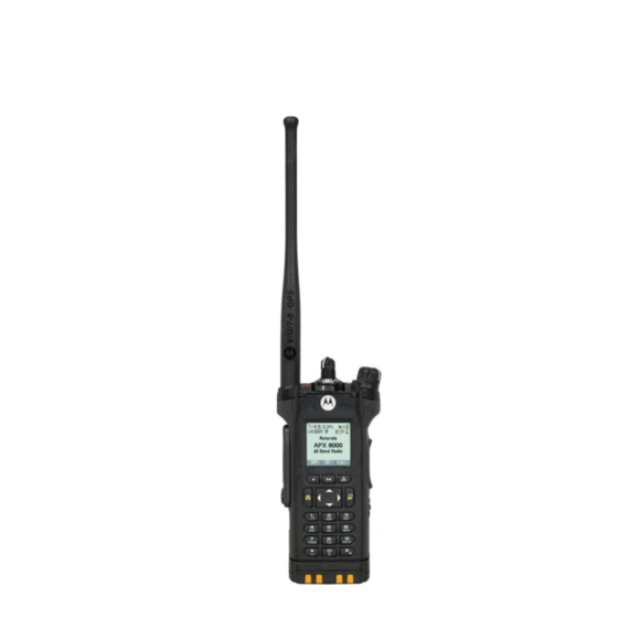
MN001424A01-AW Chapter 2 : Getting Started Attaching the Antenna Prerequisites: Ensure the radio is turned off before attaching the antenna. Procedure: 1 Set the antenna in the receptacle. 2 Turn the antenna clockwise to attach to the radio. 3 To remove the antenna, turn the antenna counterclockwise. NOTE: When removing the antenna, ensure that the radio is turned off. -
Page 19: Adjusting The Volume
MN001424A01-AW Chapter 2 : Getting Started • If the power-up test is successful, you see a splash screen on the radio display, followed by the Home screen and the Codeplug Alias. • If the power-up test is unsuccessful, you see Error XX/YY (XX/YY is an alphanumeric code). -
Page 20: Chapter 3: Radio Controls
MN001424A01-AW Chapter 3 : Radio Controls Chapter 3 Radio Controls This chapter explains the buttons and functions to control the radio. Radio Parts and Controls Antenna LED Indicator... - Page 21 MN001424A01-AW Chapter 3 : Radio Controls Top (Orange) Button This button is usually programmed as the Emergency button. Microphone Accessory Connector Home Button Press to return to the Home screen. 4-Way Navigation Buttons Use these buttons for list scrolling and navigating around the menu hierarchy. Battery Latch Keypad Use the keypad to enter alphanumeric characters for dialing, contact entries, and text...
-
Page 22: Programmable Features
MN001424A01-AW Chapter 3 : Radio Controls Main Speaker Microphone Programmable Features Your system administrator can program the programmable buttons as shortcuts to radio functions or preset channels/groups depending on the duration of a button press. Some functions can also be programmed to the radio switches. - Page 23 MN001424A01-AW Chapter 3 : Radio Controls Location Displays the current location (latitude, longitude, time, and date), and also the distance and bearing to another location, or toggles GPS/Location between on and off. Fall Alert Clear Allows you to clear the Fall Alert mode alarm and exit Fall Alert feature. Message Allows you to access the message list.
-
Page 24: Assignable Settings Or Utility Functions
MN001424A01-AW Chapter 3 : Radio Controls Secure Transmission Select Toggles secure transmission between on and off. Selective Call (Conventional Only) Calls an assigned radio. Site Display/Search (Trunking Only) Short press – Displays the current site ID and Received Signal Strength Indicator (RSSI) value. Long press –... - Page 25 MN001424A01-AW Chapter 3 : Radio Controls Volume Set Tone Sets the volume set tone.
-
Page 26: Chapter 4: Status Indicators
MN001424A01-AW Chapter 4 : Status Indicators Chapter 4 Status Indicators This section explains the status indicators of the radio. Battery Charge Status Your radio indicates the battery charge status through LED, sounds, and the battery icon on the display. You can also check the battery charge status by using the menu entry. Battery Protection is activated when the battery is low or operating in extremely low temperatures to extend radio communication. -
Page 27: Accessing The Battery Info Screen
MN001424A01-AW Chapter 4 : Status Indicators Gauge Battery Charge 11% to 25% Top Display: 10% or less (The gauge begins blinking at 10%) Top Display: 4.1.2 Accessing the Battery Info screen This feature displays the current capacity and charges cycles of your battery when an IMPRES battery is powering your radio. -
Page 28: Led Indications
MN001424A01-AW Chapter 4 : Status Indicators • The red LED blinks continuously. NOTE: The radio alerts you when NNTN8921and NNTN8930 batteries are attached to the radio because these batteries are not supported. The radio is not HAZLOC-certified and resets if these batteries are used. - Page 29 MN001424A01-AW Chapter 4 : Status Indicators Icon Description The radio is receiving a call or data. Top Display: The radio is transmitting a call or data. Top Display: The radio received an Individual Call. For IMPRES 2 battery operation only – the icon shown indicates the charge remaining in the battery.
- Page 30 MN001424A01-AW Chapter 4 : Status Indicators Icon Description The radio is scanning a scan list. Top Display: Blinking dot The radio detects activity on the designated Priority-One channel. Top Display: Steady dot The radio detects activity on the designated Priority-Two channel. Top Display: On steady The radio is in View mode...
- Page 31 MN001424A01-AW Chapter 4 : Status Indicators Icon Description Contains Zone 73, Zone 74, and Zone 75. Secure operation. Top Display: Clear operation. Blinking Receiving an encrypted voice call. The radio is operating in an Advanced Encryption Standard (AES) secure channel. The AES operation is cleared.
-
Page 32: Tms Status Icons
MN001424A01-AW Chapter 4 : Status Indicators Icon Description Blinking The Automatic Registration Service (ARS) user login failed while in broad- band system. The radio is receiving the broadband signal. The radio is transmitting the broadband signal. The radio is receiving and transmitting the broadband signal. The ARS user logged on successfully with the broadband system. -
Page 33: Call Type Icons
MN001424A01-AW Chapter 4 : Status Indicators Icon Description The selected text message in the inbox is not read. The selected text message in the inbox is read. The message has normal priority without a request for reply. The Request Reply feature is toggled on before the message is sent. -
Page 34: Intelligent Lighting Indicators
MN001424A01-AW Chapter 4 : Status Indicators Intelligent Lighting Indicators This feature temporarily changes the backlight of the top display screen to help signal that a radio event has occurred. This feature temporarily changes the backlight of the top display screen, and adds a color bar to the main display screen to help signal that a radio event has occurred. - Page 35 MN001424A01-AW Chapter 4 : Status Indicators You Hear Tone Name Heard Fall Alert (Man Down) When radio initiates Fall Alert mode. Entry Long, Low- Time-Out Timer Timed After time out. Pitched Tone Talk Prohibit/PTT In- (When PTT button is pressed) transmissions are not hibit allowed.
-
Page 36: Phone Call Displays And Alerts
MN001424A01-AW Chapter 4 : Status Indicators You Hear Tone Name Heard Short, High- Low-Battery Chirp When battery is below preset threshold value. Pitched Tone (Chirp) Two High- GPS Fails When the GPS fails or loses signal. Pitched Tones Ringing Fast Ringing When system is searching for target of Private Call. -
Page 37: Display Color Change On Channel
MN001424A01-AW Chapter 4 : Status Indicators You Hear You See When Notes A Long No phone You press the PTT Press to hang up. The radio re- Tone button and the phone turns to the Home screen. system is not availa- ble. -
Page 38: Chapter 5: General Radio Operation
MN001424A01-AW Chapter 5 : General Radio Operation Chapter 5 General Radio Operation This chapter explains the general operations of your radio. Selecting a Zone When and where to use: A zone is a group of channels. NOTE: Any reference to Zone Select Switch refers to Zone Select using the Menu. Do one of the following to select a radio channel. -
Page 39: Mode Select Feature
MN001424A01-AW Chapter 5 : General Radio Operation b. Press the Menu Select button directly below Chan . to the required channel. d. Press the Menu Select button directly below Sel to confirm the selected channel. • Select a channel using the radio menu Channel Up or Channel Down: to ChUp or ChDn. -
Page 40: Receiving And Responding To A Radio Call
MN001424A01-AW Chapter 5 : General Radio Operation Procedure: 1 Toggle from your current zone and channel to the required zone and channel. 2 Press and hold the button you desire to program. You hear a short, medium-pitched tone when the zone and channel is saved. If the Preconfigurable Preset Zone and Channel field is disabled, a negative tone sounds. -
Page 41: Receiving And Responding To A Telephone Call (Trunking Only)
MN001424A01-AW Chapter 5 : General Radio Operation When you receive a Private Call, you hear two alert tones and the LED blinks green. The display shows Call received and the call received icon blinks. Procedure: 1 Perform one of the following actions: •... -
Page 42: Making A Private Call (Trunking Only)
MN001424A01-AW Chapter 5 : General Radio Operation • For ASTRO Conventional system, the LED lights up solid red. The display shows the talkgroup alias or ID. • For Trunking system, the LED lights up solid red. 4 Wait for the Talk Permit Tone. 5 Speak clearly into the microphone. -
Page 43: Making A Telephone Call (Trunking Only)
MN001424A01-AW Chapter 5 : General Radio Operation • To access this feature using a preprogrammed button, press the preprogrammed Enhanced Private Call button to dial the preprogrammed ID (number) and initiate the Private Call. Proceed to step • or to Call, and press the Menu Select button directly below Call. The display shows the last transmitted or received ID. -
Page 44: Switching Between Repeater Or Direct Operation Button
MN001424A01-AW Chapter 5 : General Radio Operation Switching Between Repeater or Direct Operation Button The Repeater Operation increases the radio coverage area by connecting with other radios through a repeater. The transmit and receive frequencies are different. The Direct or “talkaround operation” allows you to bypass the repeater and connect directly to another radio. -
Page 45: Monitoring Conventional Mode
MN001424A01-AW Chapter 5 : General Radio Operation a. Select the desired zone and channel. b. Listen for a transmission. c. Adjust the Volume Control Knob if necessary. d. Press and hold the PTT button to transmit. The LED lights up solid red. e. -
Page 46: Chapter 6: Additional Performance Enhancement
MN001424A01-AW Chapter 6 : Additional Performance Enhancement Chapter 6 Additional Performance Enhancement The following performance enhancements are some of the latest creations designed to enhance the security, quality, and efficiency of the radios. ASTRO 25 Enhanced Data ASTRO 25 Enhanced Data is optimized to handle different message sizes and variable update rates from different applications of the radio. -
Page 47: P25 Digital Vehicular Repeater System
P25 Digital Vehicular Repeater System Motorola Solutions offers an MSI Certified APX compatible, third party, P25 Digital Vehicular Repeater System (DVRS). This provides low-cost portable radio coverage in areas where only mobile radio coverage is available. -
Page 48: Chapter 7: Advanced Features
MN001424A01-AW Chapter 7 : Advanced Features Chapter 7 Advanced Features This chapter explains the operations of the features available in your radio. ViQi ViQi is a virtual assistant that helps you manage your radio and perform information lookups using voice commands. This feature is purpose-built for public safety and is active when you press the assigned ViQi button on the radio, Remote Speaker Microphone (RSM), or compatible mobile microphone. -
Page 49: Using Viqi Virtual Partner
MN001424A01-AW Chapter 7 : Advanced Features Query Examples “Am I still at the <location>?” NOTE: ViQi will ask for more information to complete the query. Target Location “Where is <unit name>?” “Tell me where <unit name> is.” NOTE: ViQi will ask for more information to complete the query. 7.1.1 Using ViQi Virtual Partner Prerequisites:... -
Page 50: Making A Selective Call
MN001424A01-AW Chapter 7 : Advanced Features The speaker unmutes. Procedure: 1 Hold the radio vertically 1 to 2 inches (2.5 to 5.0 cm) from your mouth. 2 Press and hold the PTT button to talk. Release the PTT button to listen. 7.2.1.2 Making a Selective Call Prerequisites: Your radio must be preprogrammed for you to use this feature. -
Page 51: Sending A Status Call
MN001424A01-AW Chapter 7 : Advanced Features • to Preset for the preset preprogrammed Talkgroup. • to the required talkgroup. 3 Press the Menu Select button directly below Sel to save the currently selected talkgroup and return to the Home screen. If the encryption key associated to the new Talkgroup is erased, you hear a momentary key fail tone and the display shows Key fail. -
Page 52: Dynamic Regrouping (Trunking Only)
MN001424A01-AW Chapter 7 : Advanced Features Procedure: 1 Press the preprogrammed Priority Dispatch button. A tone sounds and the radio enters Priority Dispatch mode. The radio exits this mode when the Priority Dispatch Time Out Timer expires. 2 Before the Priority Dispatch Time Out Timer expires, press and hold the PTT button to transmit. The display shows the Priority Talkgroup alias. -
Page 53: Dynamic Zone Programming
MN001424A01-AW Chapter 7 : Advanced Features • or to Rpgm then press the Menu Select button directly below Rpgm to send reprogram request to the dispatcher. The display shows Reprogram Rqst and Please wait. If you hear five beeps, the dispatcher has acknowledged the reprogram request. The display shows Ack received and the radio returns to the Home screen. -
Page 54: Deleting A Channel In The Dynamic Zone
MN001424A01-AW Chapter 7 : Advanced Features 2 Press the Menu Select button directly below Edit. The display shows Search Options screen. to List Selection. Press the Menu Select button directly below Sel . The display shows Select Zone screen. to the required zone. Press the Menu Select button directly below Sel . The display shows Select Chan screen. -
Page 55: Remote Monitor
MN001424A01-AW Chapter 7 : Advanced Features 2 Press the Menu Select button directly below Sel to select source zone. 3 When connecting to the target radio, one of the following scenarios occurs: • If the radio is compatible, the radio displays Target radio connected. Proceed to step •... -
Page 56: Making A Private Call From Contacts
MN001424A01-AW Chapter 7 : Advanced Features • Phone Call • Private Call • Selective Call • Call Alert Each entry within Contacts contains the following information: • Call Alias (Name) • Call ID (Number) • Call Type (Icon) • WACN ID (ASTRO 25 Trunking IDs only) •... -
Page 57: Removing A Contact From A Call List
MN001424A01-AW Chapter 7 : Advanced Features to the entry you want to add and press the Menu Select button directly below Optn . to Add to CallLst and press the Menu Select button directly below Sel . 4 Perform one of the following actions: •... -
Page 58: Intelligent Priority Scan
MN001424A01-AW Chapter 7 : Advanced Features • Talkgroup Scan List • Trunking Priority Monitor Scan List Refer to a qualified radio technician for the maximum number of Scan Lists to be programmed in your radio. 7.5.1 Intelligent Priority Scan This feature allows you to add or delete conventional channels and trunking talkgroups from multiple systems into the priority scan lists. -
Page 59: Changing The Scan List Status
MN001424A01-AW Chapter 7 : Advanced Features • Press to exit scan list programming and return to the Home screen. Viewing and Changing the Priority Status on page 59 for more information on how to add and/or change the priority of the currently displayed channel in the scan list. 7.5.4 Changing the Scan List Status Procedure:... -
Page 60: Scan
MN001424A01-AW Chapter 7 : Advanced Features Scan This feature allows you to monitor traffic on different channels by scanning a programmed list of channels. Scanning is halted if you initiate a call and resumes when the call has ended. 7.6.1 Turning Scan On or Off Procedure: Perform one of the following actions:... -
Page 61: Restoring A Nuisance Channel
MN001424A01-AW Chapter 7 : Advanced Features • or to Nuis and press the Menu Select button directly below Nuis. The radio continues scanning the remaining channels in the list. 7.6.4 Restoring a Nuisance Channel Procedure: To restore the deleted nuisance channel, perform one of the following actions: •... -
Page 62: Recent Calls
MN001424A01-AW Chapter 7 : Advanced Features a. Press the preprogrammed Call Alert Paging button to send a page to the preprogrammed The display shows Paging...<Number>. If the call alert page is sent successfully, you hear a tone and the display shows Ack received. -
Page 63: Viewing Recent Calls
MN001424A01-AW Chapter 7 : Advanced Features • Call Alert • Selective Call • Private Call • Phone Call (Outgoing Only) • Emergency Call (Incoming Only) NOTE: The Log Dispatch Calls Enable field need to be enabled in Customer Programming Software (CPS) for your radio to log the dispatch call. 7.8.1 Viewing Recent Calls Do one of the following to view recent calls. -
Page 64: Instant Recall
MN001424A01-AW Chapter 7 : Advanced Features Option Actions c Select All Calls. d Press Yes. Deleting non-emergency calls a Press Optn. b Select Delete Calls. c Select Non-Emer Calls. d Press Yes. When you have successfully deleted all calls, your display shows All calls deleted and the Recent Calls list is empty. -
Page 65: In-Call User Alert
MN001424A01-AW Chapter 7 : Advanced Features to the required call and press the Menu Select button directly below Play. Radio playback the selected call and auto playback the saved calls in chronological order. d. Press the Menu Select button directly below Stop to stop the radio playback. e. -
Page 66: Special Considerations For Emergency Operation
MN001424A01-AW Chapter 7 : Advanced Features • Emergency Alarm • Emergency Call • Emergency Alarm with Emergency Call • Silent Emergency Alarm One channel supports only one Emergency mode. The radio responds differently when pressing the programmed Emergency button in each channel. Only one Emergency mode can be assigned to the Emergency button. -
Page 67: Emergency Keep-Alive
MN001424A01-AW Chapter 7 : Advanced Features 7.10.2 Emergency Keep-Alive This feature prevents your radio from turning off when in Emergency mode. If this feature is enabled, you are required to exit Emergency mode before turning off your radio. 7.10.3 Exiting Emergency Operation If an Emergency operation is triggered on your radio, the dispatch console or radios configured as Supervisor can exit the Emergency operation. -
Page 68: Sending Remote Emergency To Specific Users
MN001424A01-AW Chapter 7 : Advanced Features 7.10.5.1 Sending Remote Emergency to Specific Users Procedure: 1 Press the programmed Remote Emergency button. 2 Select the required user of the target radio. 3 To send Remote Emergency, press the PTT button. If the ID of the target radio is valid, your radio displays sending notification and saves the ID as the last Remote Emergency ID. -
Page 69: Sending An Emergency Alarm
MN001424A01-AW Chapter 7 : Advanced Features 7.10.6 Sending an Emergency Alarm When and where to use: This feature allows you to send a data transmission, which identifies the radio sending the emergency, to the dispatcher. NOTE: The default timer of Emergency button press to activate Emergency is 50 milliseconds. This timer is programmable from 50–6200 milliseconds by a qualified technician. -
Page 70: Sending An Emergency Alarm With Emergency Call
MN001424A01-AW Chapter 7 : Advanced Features Your radio microphone is automatically activated, allowing you to communicate with the group of radios without pressing the PTT button. This activated microphone state is also known as hot mic. The hot mic applies to the first voice transmission from your radio during the Emergency call. For subsequent transmissions in the same Emergency call, you must press the PTT button. -
Page 71: Sending An Emergency Alarm And Call With Hot Mic
MN001424A01-AW Chapter 7 : Advanced Features 7.10.10 Sending An Emergency Alarm and Call with Hot Mic This feature allows you to send an Emergency Alarm and Call with hot mic to a group of radios. When and where to use: Your radio must be programmed for this type of operation. When indirect PTT such as Hot Mic is activated, the audio transmission can be configured in CPS to route the audio to the radio internal microphone, wired RSM microphone, or Bluetooth wireless microphone. -
Page 72: Receiving Emergency Beacons
MN001424A01-AW Chapter 7 : Advanced Features For more information, contact your system administrator. 7.10.12.1 Receiving Emergency Beacons When and where to use: The receiving radio displays Beacon Received, the transmitting radio Contact ID, or alias. The following methods are options on how to receive the beacon. Procedure: 1 Perform one of the following: •... -
Page 73: Responding To Evacuation Indicator
MN001424A01-AW Chapter 7 : Advanced Features • If the Fireground Zone Channel is set as default, you hear the gurgle tone and the radio displays the home screen. You are in Fireground zone channel. • If the Fireground Zone Channel is set as default, but you hear a short, low-pitched tone, the display shows Reg failed to indicate that the command terminal does not respond to Fireground Zone Channel. -
Page 74: Sending Evacuation Tone
MN001424A01-AW Chapter 7 : Advanced Features 7.12 Sending Evacuation Tone This feature enables the evacuation tone to be heard on the transmitting radio and on any radio that is able to receive the tone instruction. Procedure: Once the tone begins to sound, if the orange button is released the tone continues to alarm on all radios within the talkgroup, until the PTT button is released. -
Page 75: Man Down (Fall Alert)
MN001424A01-AW Chapter 7 : Advanced Features 7.14 Man Down (Fall Alert) Man Down (Fall Alert) is a supporting feature of the Emergency operation. The Emergency feature must be programmed for Man Down (Fall Alert) to operate. Your radio activates the Man Down (Fall Alert) feature when it achieves or exceeds a tilt angle threshold or a combination of the angle threshold and radio motion below the motion sensitivity level. -
Page 76: Exiting Fall Alert
MN001424A01-AW Chapter 7 : Advanced Features 2 Lay the radio down in a horizontal position. The radio plays an alert tone and the display shows Man-Down. Postrequisites: If Fall Alert is configured but the condition does not trigger the activation of the feature, send the radio to a qualified technician. -
Page 77: User Login Feature
MN001424A01-AW Chapter 7 : Advanced Features b. Press the Menu Select button directly below Chan . The display shows the current channel name. to the required channel or mode. d. Press Sel to confirm the displayed channel. One of the following scenarios occur: •... -
Page 78: Logging Out
MN001424A01-AW Chapter 7 : Advanced Features • If the user name is invalid, login fails and the user login failure indicator (IP indicator) icon blinks. The display also shows Login failed. • Wait for the logged in confirmation screen. If the login process is successful, the display shows the successful user login indicator (IP indicator) icon and Logged in, with Logt and Exit. -
Page 79: Sending A Quick Text Message
MN001424A01-AW Chapter 7 : Advanced Features Quick Text messages are messages that are predefined and usually consist of messages that are used most frequently. Each Quick Text message has a maximum length of 50 characters. NOTE: Query is only supported in the ASTRO 25 Advanced Messaging Solution. For more information, see ASTRO 25 Advanced Messaging Solution on page 84 Two-Factor... -
Page 80: Appending A Priority Status To A Text Message
MN001424A01-AW Chapter 7 : Advanced Features Before sending your message, you can add a priority status, request reply, or both to your message. 7.16.2.1 Appending a Priority Status to a Text Message When and where to use: NOTE: The Priority Status icon on a message does not imply that the message gets higher priority over the other messages when it is being transmitted. -
Page 81: Removing A Priority Status And A Reply Request From A Text Message
MN001424A01-AW Chapter 7 : Advanced Features to Mark Important and press the Menu Select button directly below Sel to indicate that the message is important. to Req Reply and press the Menu Select button directly below Sel to request for a reply. -
Page 82: Replying To A Received Text Message
MN001424A01-AW Chapter 7 : Advanced Features • Press and hold the preprogrammed Data Feature button or the TMS Feature button to access the Inbox. • or to TMS and press the Menu Select button directly below TMS to access the TMS feature screen. -
Page 83: Deleting A Text Message
MN001424A01-AW Chapter 7 : Advanced Features 7.16.2.10.1 Viewing a Sent Text Message Procedure: 1 Perform one of the following actions: • Press the preprogrammed Data Feature button or the TMS Feature button to access the TMS feature screen. • to TMS and press the Menu Select button directly below TMS to access the TMS feature screen. -
Page 84: Deleting All Text Messages
This feature only supports Model 3.5 and Model 2.5. The ASTRO 25 Advanced Messaging Solution allows you to quickly send and receive messages and run database queries directly from your data-enabled Motorola Solutions two-way radios. Federal mandate requires Two-Factor Authentication when querying Federal and State databases. -
Page 85: Logging In Using The Two-Factor Authentication
MN001424A01-AW Chapter 7 : Advanced Features 7.17.1.1 Logging in using the Two-Factor Authentication Procedure: 1 Perform one of the following actions: • Press the preprogrammed User Login button. • or to User, and press the Menu Select button directly below User. The display shows the User Login screen. -
Page 86: Logging Out Of Two-Factor Authentication
MN001424A01-AW Chapter 7 : Advanced Features 7.17.1.2 Logging out of Two-Factor Authentication When and where to use: NOTE: Private data refers to all messages in the text messaging Inbox, Draft, and Sent folder. The next user is able to access the Inbox, Draft, and Sent messages if private data is not deleted. -
Page 87: Receiving A Query
MN001424A01-AW Chapter 7 : Advanced Features to scroll through the list of messages and press the Menu Select button directly below Sel to select the required message. The message appears on the Compose screen, with a blinking cursor at the end of it. 6 Use the keypad to edit the message, if required. -
Page 88: Selecting Clear Transmissions
MN001424A01-AW Chapter 7 : Advanced Features • If the selected channel is preprogrammed for clear-only operation, when you press the PTT button, you hear an invalid mode tone and the display shows Clear TX only. • The radio does not transmit until you set the Secure/Clear switch to the clear position. •... -
Page 89: Multikey Feature
MN001424A01-AW Chapter 7 : Advanced Features 7.18.3.2 Multikey Feature This feature allows your radio to be equipped with different encryption keys and supports the DES-OFB algorithm. There are two types of encryption keys: Conventional Multikey The encryption keys are strapped on a one-per-channel basis, through Customer Programming Software (CPS). -
Page 90: Erasing Encryption Keys
MN001424A01-AW Chapter 7 : Advanced Features Every channel to which one of the original keys was tied now has the equivalent new key instead. Procedure: or to KSet and press the Menu Select button directly below KSet. The display shows the last user-selected and stored keyset, and the available keyset menu selections. -
Page 91: Requesting An Over-The-Air Rekey
MN001424A01-AW Chapter 7 : Advanced Features b. While holding Top Side (Select) button down, press the Top (Orange) button. The display shows Please wait. When all the encryption keys have been erased, the display shows All keys erased. NOTE: Do not press the Top (Orange) button before pressing the Top Side (Select) button, unless you are in an emergency situation as this sends an emergency alarm. -
Page 92: Hear Clear
MN001424A01-AW Chapter 7 : Advanced Features 7.18.3.9 Hear Clear Hear-Clear is a noise reduction system that consists of Companding and Random FM Noise Canceller. Companding Reduces the channel noise, such as OTA transmission that is predominantly present in UHF2 and 900 MHz channel with the following features: Compressor Reduces the background noise flow and the speech signal at transmitting radio. -
Page 93: Outdoor Location Feature
MN001424A01-AW Chapter 7 : Advanced Features • Stay in the open as the GPS feature works best when there is nothing between your radio and the open sky. 7.20.1 Outdoor Location Feature This feature only supports Model 3.5 and Model 2.5. This feature allows you to determine your current location using a location menu, and your current distance and bearing in relation to another location. -
Page 94: Accessing The Outdoor Location Feature
MN001424A01-AW Chapter 7 : Advanced Features Military Grid Reference System (MGRS) can only be enabled through Customer Programming Software (CPS) configuration. When the MGRS coordinate is enabled, all location coordinates are displayed in the MGRS format, including the editable locations in GPS. 7.20.4 Accessing the Outdoor Location Feature When and where to use:... -
Page 95: Saving A Waypoint
MN001424A01-AW Chapter 7 : Advanced Features to the preferred location format and press the Menu Select button directly below Sel. The front display shows the location with the selected format. NOTE: If the SLD99 format is selected and the range is invalid, the display shows –––––– –––––- on the location. -
Page 96: Deleting A Single Saved Waypoint
MN001424A01-AW Chapter 7 : Advanced Features 6 To return to the previous screen, press the Menu Select button directly below Back, or to return to the Home screen, press , the PTT button, or the preprogrammed GPS button. 7.20.8 Deleting a Single Saved Waypoint Prerequisites: Ensure your radio shows the current location on the screen. -
Page 97: Location Feature In Emergency Mode
MN001424A01-AW Chapter 7 : Advanced Features Procedure: 1 Press the Menu Select button directly below Optn. to Dist frm here and press the Menu Select button directly below Sel . The display shows a list of waypoints. to the required waypoint and press the Menu Select button directly below Sel . The display shows the distance and bearing from the current to the selected coordinates. -
Page 98: Mission Critical Geofence (Astro 25 Trunking)
MN001424A01-AW Chapter 7 : Advanced Features 7.21 Mission Critical Geofence (ASTRO 25 Trunking) This feature allows your radio to use the Global Positioning System (GPS) receiver to determine its location at frequent intervals, and evaluate if the radio is within the Geofence area in real time. Geofence is a virtual perimeter based on the GPS to define a geographical area on earth. -
Page 99: Mission Critical Geofence
MN001424A01-AW Chapter 7 : Advanced Features changes. Voice Announcement of the new channel only works if that channel is configured with Voice Announcement. 7.21.2 Mission Critical Geofence This feature allows the radio to use the GPS receiver to determine radio location at frequent intervals and evaluate if the radio is within the Geofence area in real time Check with your dealer or qualified technician to program the geofence coordinates and actions. -
Page 100: Imbalanced Coverage
In addition, a radio operating on a lower priority broadband connection returns to the higher priority or quality connection while idle on SmartConnect. Your radio can connect through a fixed Wi-Fi access point in buildings or in-vehicle Broadband modem such as the following modems: • Motorola Solutions VML750 • Sierra Wireless MP70 • Sierra Wireless GX450 Your radio displays the SmartConnect capable icon on the SmartConnect enabled channel. -
Page 101: Site Trunking Feature
MN001424A01-AW Chapter 7 : Advanced Features Your radio displays Out of Range when both LMR and SmartConnect are unavailable. NOTE: The SmartConnect feature must be programmed by a qualified radio technician. For more information, contact your system administrator. The Searching Site display is only visible on the radio when you enable this feature through the Customer Programming Software (CPS). -
Page 102: Changing The Current Site
(your radio) and the location of the receiver (your device or accessory). Obstacles that can cause an obstruction in the line-of-sight include trees, buildings, mountains, cars, and others. For high degree of reliability, Motorola Solutions recommends to NOT separate the radio and the accessory. -
Page 103: Pin Authentication In Pairing
MN001424A01-AW Chapter 7 : Advanced Features At the fringe areas of reception, both voice and tone quality will start to sound "garbled" or "broken". To correct this problem, simply position the accessory and radio closer to each other (within the 10 meter defined range) to re-establish clear audio reception. -
Page 104: Pairing The Authentication Pin With The Generated Numeric Pin
MN001424A01-AW Chapter 7 : Advanced Features If you choose to reject the pairing process, the display shows Cancel pairing in progress... followed by <Device Friendly Name> pair canceled and return to Home screen. 2 Perform one of the following actions when the display shows Compare PIN: XXXXXX.: •... -
Page 105: Viewing And Clearing The Bluetooth Device Information
MN001424A01-AW Chapter 7 : Advanced Features • The display shows <Device Friendly Name> pair failed (if the PIN numbers are different). • <Device Friendly Name> connect failed (if the connection fails). The display returns to Available Dev screen. 7.23.3 Viewing and Clearing the Bluetooth Device Information Procedure: or to BT. -
Page 106: Responder Alert Sensors
MN001424A01-AW Chapter 7 : Advanced Features 2 Place the handheld close to the radio aligning the Bluetooth Pairing Location on the handheld with the Bluetooth Pairing Location on the radio. If the pairing process is successful, you hear an incremental-pitched tone from the radio. The radio begins to connect to the handheld. -
Page 107: Weapon Fired Sensor
MN001424A01-AW Chapter 7 : Advanced Features 7.23.5.2 Weapon Fired Sensor This feature allows the radio to send an Over-The-Air (OTA) notification when a weapon enabled with the sensor is fired. The event is immediately sent to the system to alert the dispatcher of the weapon fired incident. -
Page 108: Astro 25 (P25) Programming Over Project 25 (Pop25)
MN001424A01-AW Chapter 7 : Advanced Features • If the preprogrammed Sensor button or the preprogrammed Menu Select button is long- pressed, the over-the-air (OTA) sensor notification is enabled. 7.23.5.5.2 Disabling the Sensor Permanently Procedure: 1 Long-press the preprogrammed Sensor button or the preprogrammed Menu Select button to permanently disable the sensors. -
Page 109: Voice Announcement
MN001424A01-AW Chapter 7 : Advanced Features • If you choose to accept, the display shows Programming Dont power off to indicate that the upgrade is about to begin. The radio resets to install the upgrade. In the case of configuration data upgrade, the process only takes a few seconds. -
Page 110: Sending Ssa Notification To All Sites
MN001424A01-AW Chapter 7 : Advanced Features 2 Press the Menu Select button directly below SSA. The display shows the Site Alert screen. to Start Alert and press the Menu Select button directly below Sel. The display shows the Select Site screen. to the desired Site Alias. -
Page 111: Sending Ssa Notification To All Available Sites
MN001424A01-AW Chapter 7 : Advanced Features 7.26.3 Sending SSA Notification to All Available Sites Procedure: or to SSA. 2 Press the Menu Select button directly below SSA. The display shows the Site Alert screen. to Start Alert and press the Menu Select button directly below Sel. The display shows the Select Site screen. -
Page 112: Stopping Ssa Notification Of All Sites
MN001424A01-AW Chapter 7 : Advanced Features 7.26.5 Stopping SSA Notification of All Sites Procedure: or to SSA. 2 Press the Menu Select button directly below SSA. The display shows the Site Alert screen. to Stop Alert and press the Menu Select button directly below Sel. The display shows the Select Site screen. -
Page 113: Wi-Fi
MN001424A01-AW Chapter 7 : Advanced Features 7.27 Wi-Fi You can connect your radio to a Wi-Fi network for wireless programming and SmartConnect features. Your service administrator programs the Wi-Fi Service Set Identifier (SSID) or network name that your radio can connect to. 7.27.1 Turning Wi-Fi On or Off When and where to use: Do one of the following to turn Wi-Fi on or off. -
Page 114: Checking The Wi-Fi Configuration And Status Of The Radio
MN001424A01-AW Chapter 7 : Advanced Features 7.27.3 Checking the Wi-Fi Configuration and Status of the Radio Procedure: 1 Perform one of the following actions: • Long press the preprogrammed Wi-Fi button. • or to WiFi and press the Menu Select button directly below WiFi. The display shows the current status of the Wi-Fi as described next. -
Page 115: Selecting The Power Level
MN001424A01-AW Chapter 7 : Advanced Features When and where to use: This feature allows twice as many zones to be accessed from a switch, doubling the amount of switch positions. Procedure: 1 Use the programmed Basic Zone Bank button to toggle the position between Bank 1 and Bank The top display shows the status icons (A, B, C, D, E, or F) or the zone name based on the bank and switch position selected. -
Page 116: Selecting An Enhanced Zone Bank
MN001424A01-AW Chapter 7 : Advanced Features c. Press the Menu Select button directly below Sel to select the required radio profile, or press the Menu Select button directly below Exit to exit the screen without making any changes. The radio returns to the Home screen. The profile name on the Home screen indicates the current selected radio profile. -
Page 117: Locking And Unlocking The Keypad And Controls
MN001424A01-AW Chapter 7 : Advanced Features You can also maintain a minimum backlight level on the radio front display, depending on how your radio is programmed. NOTE: The backlight setting also affects the Menu Select buttons, the Navigation button, and the keypad backlighting accordingly. -
Page 118: Using The Time-Out Timer
MN001424A01-AW Chapter 7 : Advanced Features Do one of the following to turn Voice Mute on or off. You can use the options interchangeably depending on your preference and the programmed functions. Procedure: • Turning Voice Mute off or on using the preprogrammed Voice Mute button: a. -
Page 119: Conventional Squelch Operation
MN001424A01-AW Chapter 7 : Advanced Features 2 Press the Menu Select button directly below Clck. The display shows the current setting of the radio. 3 Press the Menu Select button directly below Edit. The first item blinks. 4 Perform one of the following actions: •... -
Page 120: Using Conventional Squelch Operation Features
MN001424A01-AW Chapter 7 : Advanced Features 7.28.12.1 Using Conventional Squelch Operation Features Procedure: or to Sql. 2 Press the Menu Select button directly below Sql. The display shows Squelch XX, where XX is the value for the current squelch. 3 Perform one of the following actions: •... -
Page 121: Transmit Inhibit
MN001424A01-AW Chapter 7 : Advanced Features Mode Description Transmit Inhibit on Busy Channel with Wrong You cannot transmit on an active channel with a Squelch Code squelch code or (if secure-equipped) encryption key other than your own. If the PL code is the same as yours, the transmission is not preven- ted. -
Page 122: General Radio Information
MN001424A01-AW Chapter 7 : Advanced Features • or to TxIn. Press the Menu Select button below TxIn. • Press the Transmit Inhibit programmable button. NOTE: If the user has disabled TX Inhibit using the softkey and then moves the switch to the position where TX Inhibit is enabled, the new value overwrites the menu value. -
Page 123: Viewing The Ip Information
MN001424A01-AW Chapter 7 : Advanced Features • Secure HW Version • Codeplug Alias (Optional) NOTE: To return to the Home screen, press at any time. Procedure: 1 Perform one of the following actions: • Press the preprogrammed Info button. • or to Info and press the Menu Select button directly below Info. -
Page 124: Front Panel Programming
MN001424A01-AW Chapter 7 : Advanced Features Programmable Features on page 22 for more information on the various programmable features of your radio. Procedure: 1 Perform one of the following actions: • Press the preprogrammed Info button. • or to Info and press the Menu Select button directly below Info. to Control map and press the Menu Select button directly below Sel. -
Page 125: Changing Password (Optional)
Changing Password (Optional) This feature only supports Model 3.5 and Model 2.5. Radios from the Motorola Solutions factory are provisioned with a blank password. Prerequisites: To access the protected channels, press OK when the Enter Old Password prompts you to change the password. -
Page 126: Editing Parameters
MN001424A01-AW Chapter 7 : Advanced Features 2 Enter the password and press the Menu Select button directly below Ok. to scroll through the various information. 4 Press EDIT to edit the channel parameter. 5 Change the parameter value. 6 Press OK to accept the parameter change and return to view mode. 7 Perform one of the following actions and proceed to the next step: •... - Page 127 MN001424A01-AW Chapter 7 : Advanced Features Parameter Editing Keys Value Tx Deviation 5.0 kHz/4.0 kHz/2.5 kHz Power Level High/Low Hot Keypad ON/OFF Busy LED ON/OFF Low Batt ON/OFF MPL Enable Disabled/Rx /Tx/All Scan List None/Scan List 1, 2, 3,... Zone Name The names must be configured in CPS.
-
Page 128: Chapter 8: Accessories
MN001424A01-AW Chapter 8 : Accessories Chapter 8 Accessories Not all accessories are FCC certified to operate with all radio models, band splits, or both. See the radio price pages for a list of FCC certified accessories or contact your sales representative for accessory compatibility. -
Page 129: Legal And Compliance Statements
Furthermore, Motorola Solutions reserves the right to change any products to improve readability, function, or design. Motorola Solutions does not assume any liability arising out of the applications or use of any product or circuit described herein; nor does it cover any license under its patent rights, nor the rights of others. -
Page 130: Important Safety Information
Before using the radio, read the RF Energy Exposure and Product Safety Guide for Portable Two-Way Radios which contains important operating instructions for safe usage and RF energy awareness and control for Compliance with applicable standards and Regulations. For a list of Motorola Solutions-approved antennas, batteries, and other accessories, visit the following website: https://www.motorolasolutions.com Under Industry Canada regulations, this radio transmitter may only operate using an antenna of a type and maximum (or lesser) gain approved for the transmitter by Industry Canada. -
Page 131: Fcc Licensing Information
Applying for Canadian License The operation of your Motorola Solutions radio is subject to the Radio communications Act and must comply with rules and regulations of the Federal Government's department of Industry Canada. Industry Canada requires that all operators using Private Land Mobile frequencies obtain a radio license before operating their equipment. -
Page 132: Maritime Radio Use In The Vhf Frequency Range
MN001424A01-AW Maritime Radio Use in the VHF Frequency Range Maritime Radio Use in the VHF Frequency Range Special Channel Assignments Emergency Channel If you are in imminent and grave danger at sea and require emergency assistance, use VHF Channel 16 to send a distress call to nearby vessels and the United States Coast Guard. Transmit the following information, in this order: 1 “MAYDAY, MAYDAY, MAYDAY.”... -
Page 133: Table 7: Vhf Marine Channel List
MN001424A01-AW Maritime Radio Use in the VHF Frequency Range in the semiduplex mode on the two frequency channels specified in the table below. NOTE: Simplex channels 3, 21, 23, 61, 64, 81, 82, and 83 cannot be lawfully used by the general public in US waters. - Page 134 MN001424A01-AW Maritime Radio Use in the VHF Frequency Range 156.075 160.675 156.125 160.725 156.175 160.775 156.225 160.825 156.275 160.875 156.325 160.925 67** 156.375 156.375 156.425 156.425 156.475 156.475 156.575 156.575 156.625 – 156.675 156.675 156.725 156.725 77** 156.875 – 156.925 161.525 156.975 161.575...
-
Page 135: Declaration Of Compliance For The Use Of Distress And Safety Frequencies
MN001424A01-AW Maritime Radio Use in the VHF Frequency Range Declaration of Compliance for the Use of Distress and Safety Frequencies The radio equipment does not employ a modulation other than the internationally adopted modulation for maritime use when it operates on the distress and safety frequencies specified in RSS-182 Section 7.3. -
Page 136: Limited Warranty
Product Accessories One (1) Year MOTOROLA SOLUTIONS, at its option, will at no charge either repair the Product (with new or reconditioned parts), replace it (with a new or reconditioned Product), or refund the purchase price of the Product during the warranty period provided it is returned in accordance with the terms of this warranty. -
Page 137: Ii. General Provisions
Repairs will be made only at the designated MOTOROLA SOLUTIONS repair depot. Local services are not included. MOTOROLA SOLUTIONS will pay for outbound shipping via MOTOROLA SOLUTIONS'S normal shipping methods. -
Page 138: Vi. Patent And Software Provisions
1 that MOTOROLA SOLUTIONS will be notified promptly in writing by such purchaser of any notice of such claim,... -
Page 139: Vii. Governing Law
You are also entitled to be compensated for any other reasonably foreseeable loss or damage from a failure in the goods or service. If you have any queries, please call Motorola Solutions Australia at 1800 457 439. You may also visit our website: https://www.motorolasolutions.com/en_xa/support.html... -
Page 140: Glossary
Automatic Registration Service ASTRO 25 Motorola Solutions standard for wireless digital trunked communications. ASTRO conventional Motorola Solutions standard for wireless analog or digital conventional communications. Autoscan A feature that allows the radio to automatically scan the members of a scan list. Bluetooth Bluetooth is an open wireless technology standard for exchanging data over short distances from fixed and mobile devices with high levels of security. - Page 141 MN001424A01-AW Glossary Channel A group of characteristics, such as transmit/receive frequency pairs, radio parameters, and encryption encoding. Control Channel In a trunking system, one of the channels that is used to provide a continuous, two-way/data- communications path between the central controller and all radios on the system. Conventional Typically refers to radio-to-radio communications, sometimes through a repeater.
- Page 142 It can also trigger Emergency Alarm the Post-Alert Timer is not cancelled. Mission Critical Wireless. Motorola Solutions Digital Communications. Menu Entry A software-activated feature shown at the bottom of the display. Selection of a feature is controlled by the programming of the buttons on the side of the radio.
- Page 143 MN001424A01-AW Glossary Check channel activity by pressing the Monitor button. If the channel is clear, you hear static. If the channel is in use, you hear conversation. It also serves as a way to check the volume level of the radio, since the radio “opens the squelch” when the monitor button is pressed. Multi-System Talkgroup Scan List A scan list that can include both talkgroups (trunked) and channels (conventional).
- Page 144 MN001424A01-AW Glossary PTT-The switch or button usually located on the left side of the radio which, when pressed, causes the radio to transmit. When the PTT is released, the unit returns to receive operation. Radio Frequency RF-The portion of the electromagnetic spectrum between audio sound and infrared light (approximately 10 kHz to 10 GHz).
- Page 145 MN001424A01-AW Glossary The automatic sharing of communications paths between a large number of users. Allows users to share a smaller number of frequencies because a repeater or communications path is assigned to a talkgroup for the duration of a conversation. Trunking Priority Monitor scan list A scan list that includes talkgroups that are all from the same trunking system.
Need help?
Do you have a question about the APX 8000 and is the answer not in the manual?
Questions and answers