Table of Contents
Advertisement
Quick Links
Advertisement
Table of Contents

Subscribe to Our Youtube Channel
Related Manuals for Deye SUN-25K-G04-LV


Summary of Contents for Deye SUN-25K-G04-LV
- Page 1 Grid-connected PV Inverter SUN-25K-G04-LV SUN-30K-G04-LV User Manual...
-
Page 2: Table Of Contents
Contents 1. Introduction - 1 - 1.1 Appearance Introduction - 1 - 1.2 Labels description - 2 - 1.3 Parts list - 2 - 1.4 Product handling requirements - 3 - 2. Safety warnings and instructions - 4 - 2.1 Safety signs - 4 - 2.2 Safety instructions - 4 -... - Page 3 7. Zero-export function via energy meter - 19 - 7.1 Multiple strings and parallel connection meters - 28 - 7.2 Use of zero-export function - 38 - 7.3 Notes while using zero export function - 39 - 7.4 How to browse the load power of your PV grid-tieplant on monitoring platform? - 39 - 8.
-
Page 4: About This Manual
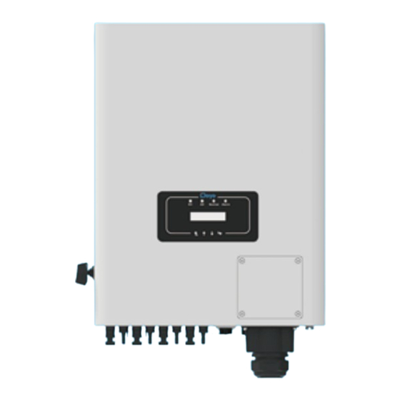
1. Introduction 1.1 Appearance Introduction On-grid Inverter can convert solar panel DC power into AC power which can directly input to the grid. Its appearance is shown below.These models contain SUN-25K-G04-LV, SUN-30K-G0 4-LV. The following is collectively referred to as “inverter”. -
Page 5: Labels Description
1.2 Labels description Description Label Caution, risk of electric shock symbol indicates important safety instructions, which if not correctly followed, could result in electric shock. The DC input terminals of the inverter must not be grounded. CE mark of conformity Please read the instructions carefully before use. -
Page 6: Product Handling Requirements
DRM connector T-type wrench Wrench x 1 Datalogger (optional) x1 (optional) x1 Three-Phase Smart Meter Solar Photovoltaic HJA4 Core Wire Female Connector Special *Sensor Clamp(optional) Meter(optional) Connector - Screw Crimp x1 Spanner x1 1.4 Product handling requirements Lift the inverter out of the packaging box and transport it to the designated installation location. transport CAUTION: Improper handling may cause personal injury! -
Page 7: Safety Warnings And Instructions
Safety warnings and instructions Improper use may result in potential electric shock hazards or burns. This manual contains important instructions that should be followed during installation and maintenance. Please read these instructions carefully before use and keep them for future reference. 2.1 Safety signs Safety symbols used in this manual, which highlight potential safety risks and important safety information, are listed as follows:... -
Page 8: Notes For Using
2.3 Notes for using The three phase string power inverter is designed and tested under related safety regulations. It can ensure the personal safety of the user. But as a electric device, it may cause shock or injury by incorrect operation. Please operate the unit under below requirements: 1. -
Page 9: Status Indicator
3.2 Status Indicator There are four LED status indicator lights in the front panel of the inverter. Please see table 3.1 for details. Indicator status Explanation Inverter detects DC input ● Low DC input voltage Grid Connected ● Grid Unavailable Under normal operating ●... - Page 10 ● Exposure to direct sunlight will increase the operational temperature of the inverter and may cause output power limiting. It is recommended that inverter installed to avoid direct sunlight or raining. ● To avoid overheating ambient air temperature must be considered when choosing the inverter installation location.
- Page 11 ≤15 ° Pic 4.2 Installation Angle ≥500mm ≥500mm Pic 4.3 Installation Gap - 08 -...
-
Page 12: Installations Tools
4.2 Installations Tools Installation tools can refer to the following recommended ones. Also, use other auxiliary tools on site. table 4-1 Tool specification Protective goggles Anti-dust mask Earplugs Work gloves Work shoes Utlity Knife Slotted screwdriver Cross screwdriver Percussion drill Pliers Marker Level... - Page 13 Procedure shows below: 1. Locate on the appropriate wall according to the bolt position on the mounting bracket, then mark the hole.On the brick wall, the installation must be suitable for the expansion bolt installation. Pic 4.5 Inverter hanging plate installation 2.
-
Page 14: Electrical Connection
2) Open circuit Voltage (Voc) of PV modules should be higher than min. start voltage. 3) The PV modules used to connected to this inverter shall be Class A rating certified according to lEC 61730. SUN-30K-G04-LV Inverter Model SUN-25K-G04-LV PV Input Voltage 400V (250V~800V) PV Array MPPT Voltage Range 200V~700V No. - Page 15 The steps to assemble the DC connectors are listed as follows: a) Strip off the DC wire about 7mm, disassemble the connector cap nut (see picture 5.3). Pic 5.3 Disassemble the connector cap nut b) Crimping metal terminals with crimping pliers as shown in picture 5.4. Pic 5.4 Crimp the contact pin to the wire c) Insert the contact pin to the top part of the connector and screw up the cap nut to the top part of the connector.
-
Page 16: Ac Input Terminal Connection
Max. DC input current should be 20A. if exceeds, it may damage the inverter and it is not covered by Deye warranty. 5.3 AC input terminal connection Do not close the DC switch after the DC terminal is connected.Connect the AC terminal to the AC side of the inverter, the AC side is equipped with Three phase AC terminals that can be conveniently connected. - Page 17 L3 PE L1 L2 Pic 5.7 AC input connection Warning: Be sure that AC power source is disconnected before attempting to wire it to the unit. 1. Before making Grid port connection, be sure to turn off AC baeaker or disconnector first. 2.
-
Page 18: The Connection Of The Ground Line
5.4 The connection of the ground line Good grounding is good for resisting surge voltage shock and improving EMI performance.There- fore, before connecting AC, DC and communication cables, you need to ground the cable firstly. For a single system, just ground the PE cable. For multiple machine systems, all PE cables of the inverter need to be connected to the same grounding copper platoon to ensure the equipotential connection. -
Page 19: Max. Over Current Protection Device
See table 5.3 below. Rated output Rated output Current for protection Inverter voltage(V) current(A) device(A) SUN-25K-G04-LV 127/133 65.7A SUN-30K-G04-LV 127/133 78.8A Table 5.3 Recommended current protector specifications 5.6 Inverter monitoring connection Inverter has the function of wireless remote monitoring. The inverter with Wi-Fi function is equipped with Wi-Fi Plug to connect the inverter and network. -
Page 20: Installation Of Datalogger
5.7 Installation of datalogger When installing the WiFi stick, tear off the sealing strip on the inverter. Insert the datalogger into the interface and fix it with a screw. The configuration of the datalogger needs to be performed after various electrical connections have been completed and the inverter DC power on. When the inverter is on the DC power, it is determined whether the datalogger is normally electrified (The LED light shines out of the shell). -
Page 21: Inverter Shutdown
6.2 Inverter Shutdown Must follow below steps while shutting down the inverter: 1. Switch off the AC breaker. 2. Wait for 30 seconds, turn off the DC switch (if any), or simply disconnect the DC input connector. The inverter will close the LCD and all LED within two minutes. 6.3 Anti-PID Function(optional) Inverter The Anti-PID module repairs the PID effect of the PV module at night.The PID module always... -
Page 22: Lcd Night Power Supply(Optional)
CHINT meter DTSU666 5(80) A is also supported, it can measure the Max. 80A current directly. More usable models of DTSU666 series , please refer to Pic 7.9-7.16. Suggest purchasing smart meters from authorized distributors of Deye or directly from Deye. When you are reading this, we believe that you have completed the connection according to... - Page 23 2 3 4 5 6 7 8 Eastron Gird Load (1,2,3,4) (5,6,7,8) B A G RS 485 RS 485 B RS 485 A Eastron SDM630-Modbus V2 Inverter Solar Panel array AC Breaker RS 485 Male connector Family load VCC_5V 485_B N L3 L2 L1 RS 485 Female connector...
- Page 24 2 3 4 5 6 7 8 Eastron Gird Load (1,2,3,4) (5,6,7,8) B A G RS 485 RS 485 B RS 485 A Eastron SDM630-Modbus V2 Inverter Solar Panel array AC Breaker RS 485 Male connector Family load VCC_5V 485_B N L3 L2 L1 RS 485 Female connector...
- Page 25 9 1 0 1 1 1 2 1 3 1 4 1 5 1 6 1 7 1 8 1 9 2 0 Eastron 15 16 17 18 19 20 1 2 3 4 Grid voltage Auxiliary Current inputs sampling power supply 1 4 1 3 1 2 RS 485...
- Page 26 9 1 0 1 1 1 2 1 3 1 4 1 5 1 6 1 7 1 8 1 9 2 0 Eastron 15 16 17 18 19 20 1 2 3 4 Grid voltage Auxiliary Current inputs sampling power supply 1 4 1 3 1 2 RS 485...
- Page 27 9 10 Grid Load Three-Phase Smart Meter (3,6,9,10) (1,4,7,10) 24 25 RS 485 CHINT DTSU666 5(80)A Pic 7.9 CHINT meter Inverter Solar Panel array AC Breaker RS 485 Male connector Family load 485_B L1 L2 L3 N VCC_5V RS 485 Female connector Three-Phase Smart Meter meter...
- Page 28 9 10 Grid Load Three-Phase Smart Meter (3,6,9,10) (1,4,7,10) 24 25 RS 485 CHINT DTSU666 5(80)A Pic 7.11 CHINT meter Inverter Solar Panel array AC Breaker RS 485 Male connector Family load 485_B L1 L2 L3 N VCC_5V RS 485 Female connector Three-Phase Smart Meter meter...
- Page 29 6 9 10 13 14 17 19 24 Three-Phase Smart Meter 230/400V, 3~100A/40mA 50/60Hz 24 25 Phase A current =5.000A 13 14 16 17 19 21 RS485 Phase B current =5.001A CHINT DTSU666 3x230/400V 3~100A/40mA Pic 7.13 CHINT meter Phase C current =5.002A Inverter Solar Panel array AC Breaker...
- Page 30 6 9 10 13 14 17 19 24 Three-Phase Smart Meter 230/400V, 3~100A/40mA 50/60Hz 24 25 Phase A current =5.000A 13 14 16 17 19 21 RS485 Phase B current =5.001A CHINT DTSU666 3x230/400V 3~100A/40mA Phase C current =5.002A Pic 7.15 CHINT meter Inverter Solar Panel array AC Breaker...
-
Page 31: Multiple Strings And Parallel Connection Meters
7.1 Multiple strings and parallel connection meters This application is that when the string inverters work in parallel, there is only one power grid and one load, and only one meter can be connected to prevent reverse current, so only this many-to-one anti-reverse current connection can be connected. - Page 32 Name Description Range AVG: Average power of three phase is zero exported. MIN: Phase with minimum load power is zero Exp_Mode AVG/MIN exported, while the other two phase may be in purchase mode. CT ratio of power grid side meter when extern CT is CT_Ratio 1-1000 applied.
- Page 33 2 3 4 5 6 7 8 Eastron Gird Load (1,2,3,4) (5,6,7,8) B A G RS 485 RS 485 B RS 485 A Eastron SDM630-Modbus V2 Master(Mst) Grid RS485 L1 L2 L3 N 485_B 485_A VCC_5V 485_B RS 485 Female connector Slave2(Slv2) Slave1(Slv1) RS485...
- Page 34 2 3 4 5 6 7 8 Eastron Gird Load (1,2,3,4) (5,6,7,8) B A G RS 485 RS 485 B RS 485 A Eastron SDM630-Modbus V2 Generator Master(Mst) RS485 L1 L2 L3 N 485_B 485_A VCC_5V 485_B RS 485 Female connector Slave2(Slv2) Slave1(Slv1) RS485...
- Page 35 9 1 0 1 1 1 2 1 3 1 4 1 5 1 6 1 7 1 8 1 9 2 0 Eastron 1 2 3 4 15 16 17 18 19 20 Grid voltage Auxiliary Current inputs sampling power supply 1 4 1 3 1 2 RS 485...
- Page 36 9 1 0 1 1 1 2 1 3 1 4 1 5 1 6 1 7 1 8 1 9 2 0 Eastron 1 2 3 4 15 16 17 18 19 20 Grid voltage Auxiliary Current inputs sampling power supply 1 4 1 3 1 2 RS 485...
- Page 37 9 10 Grid Load Three-Phase Smart Meter (3,6,9,10) (1,4,7,10) 24 25 RS 485 CHINT DTSU666 5(80)A Pic 7.26 CHINT meter Master(Mst) AC Breaker Solar Panel array Slave1(Slv1) AC Breaker Slave2(Slv2) Solar Panel array AC Breaker Solar Panel array AC Breaker load VCC_5V 485_B...
- Page 38 9 10 Grid Load Three-Phase Smart Meter (3,6,9,10) (1,4,7,10) 24 25 RS 485 CHINT DTSU666 5(80)A Pic 7.28 CHINT meter Master(Mst) AC Breaker Solar Panel array Slave1(Slv1) AC Breaker Slave2(Slv2) Solar Panel array AC Breaker Solar Panel array AC Breaker load VCC_5V 485_B...
- Page 39 6 9 10 13 14 17 19 24 Three-Phase Smart Meter 230/400V, 3~100A/40mA 50/60Hz 24 25 Phase A current =5.000A 13 14 16 17 19 21 RS485 Phase B current =5.001A CHINT DTSU666 3x230/400V 3~100A/40mA Pic 7.30 CHINT meter Phase C current =5.002A Master(Mst) AC Breaker Solar Panel array...
- Page 40 6 9 10 13 14 17 19 24 Three-Phase Smart Meter 230/400V, 3~100A/40mA 50/60Hz 24 25 Phase A current =5.000A 13 14 16 17 19 21 RS485 Phase B current =5.001A CHINT DTSU666 3x230/400V 3~100A/40mA Pic 7.32 CHINT meter Phase C current =5.002A Master(Mst) AC Breaker Solar Panel array...
-
Page 41: Use Of Zero-Export Function
7.2 Use of zero-export function When the connection is completed, the following steps should be refered to use this function: 1. Turn on the AC switch. 2. Turn on the DC switch, waiting for the inverter's LCD is turned on. 3. -
Page 42: Notes While Using Zero Export Function
7.3 Notes while using zero export function For your safety and the operation of limiter function of the inverter, we put forward the following suggestions and precautions: Safety Hint: Under zero export mode we strongly recommend that the two PV arrays are formed by the same number of PV panels of the same size, which will make the inverter more responsive to limit the power. - Page 43 And then choose your system type as “Self-consumption” Edit Plant Cancel Done Address : Basic Info YongJiang Road, Beilum,NingBo, 315806, China System Info Yield Info Coordinates : Owner Info Longitude 19.03 Latitude 36.11 ” ” Time Zone : Creation Time : 2020/04/08 (UTC+08:00) Beijing,Chongqing,Hong Kong,Urumqi System Info...
-
Page 44: General Operation
8. General Opera�on During normal operation, the LCD shows the current status of the inverter, including the current power, total generation, a bar chart of power operation and inverter ID,etc. Press the Up key and the Down key to see the current DC voltage, DC current, AC voltage, AC current,inverter radiator temperature,software version number and Wifi connection state of the inverter. - Page 45 Ac�veP Q-Mode VRated Q(%) ReactP Exp_Mode Fun- ISO CT_Ra�o 0 Fun RCD FeedIn SelfCheck Shunt ShuntQTY Island Generator Meter G.CT Setup G.MFR Limiter G.FeedIn Running param G.Pout Feed-in V1-V12 G.Cap DC1-Wind OFF/ON MPPT Num DC2-Wind OFF/ON WindTurbine Cancel OF-Derate UF-Uprate WGRa WGraStr LVRT...
- Page 46 *Note: These parameters will be avaiable after the meter is EN50549-1-PL connected successfully. Otherwise, it won't show. EN50549-1 IEC61727 Attention: For running param detail on the LCD display, please CUSTOM refer to the official Deye website https://www.deyeinverter.com VDE_4105 VDE_0126 Spain CEI_0-21 G98_G99 NB/T 32004-B...
-
Page 47: The Initial Interface
8.1 The initial interface From the initial interface, you can check PV power, PV voltage, grid voltage, inverter ID, model and other infomation. Power: Power: State: Standby State: Com.Error Pic 8.2 The initial interface Press UP or Down, you can check inverter DC voltage, DC current, AC voltage, AC current and inverter temperature. -
Page 48: Submenus In The Main Menu
ImpEp: Daily energy purchased from grid; ImpEp: 0.00KWh Total: Total energy purchased from grid. Total : 0.00KWh Pic 8.11 Electrical energy ExpEp: Daily energy sold to grid; ExpEp: 0.00KWh Total: Total energy sold to grid. Total : 0.00KWh Pic 8.12 Electrical energy 8.2 Submenus in the Main Menu There are five submenus in the Main Menu. - Page 49 8.2.3 ON/OFF setting ON / OFF << Turn ON << Setup Turn OFF Turn ON Turn OFF << Cancel << Cancel Pic 8.15 ON/OFF setting When the inverter is turned off, it stops working immediately, and go to standby mode and then will go to self-test program again.
-
Page 50: System Param Setting
8.3 System param setting System Param includes time set, language set, display set and factory reset. Time Set << Display Set Language Set Factory Reset << Factory Reset Set Restore << Pic 8.17 System Param 20200522 OK English << Polski 08:11:21 Cancel Pic 8.18 Time Bright Delay... -
Page 51: Protect Param Setting
8.4 Protect Param setting Warning: Engineer Only. We will set the param depends on the safety requirements, so customers don't need to reset it. The password is same as 8.4 Running param PassWord GridStanderd << Advanced Back << Pic 8.24 Password Braszil EN50549-1 EN50549-1-PL <<... - Page 52 OverVolt OverVolt Point 240.0V << Delay 1000ms << OverVolt OverVolt Point 240.0V << Delay 1000ms << OverVolt OverVolt Point 240.0V << Delay 1000ms << UnderVolt UnderVolt Point 235.0V << Delay 1000ms << UnderVolt UnderVolt Point 235.0V << Delay 1000ms << UnderVolt UnderVolt Point...
-
Page 53: Comm. Param Setting
UnderFreq Lv2 UnderFreq Lv2 Point 48.00Hz << Delay 1000ms << UnderFreq Lv3 UnderFreq Lv3 Point 48.00Hz << Delay 1000ms << Reconnection Reconnection 0.0V << Vdown 0.0V << Reconnection Reconnection 0.00Hz << Fdown 0.00Hz << OV 10 Minutes 10 Minutes Enable OFF <<... -
Page 54: Repair And Maintenance
9. Repair and Maintenance String type inverter doesn’t need regular maintenance. However,debris or dust will affect heat sink’s thermal performance. It is better to clean it with a soft brush. If the surface is too dirty and affect the reading of LCD and LED lamp, you can use wet cloth to clean it up. High Temperature Hazard: When the device is running, the local temperature is too high and the touch can cause burns. -
Page 55: Error Code
Check the solar panel output connection. Failure in reading memory (EEPROM). Restart the inverter if the Read the memory error fault still exists, contact your installer or Deye service. Failure in writing memory (EEPROM). Restart the inverter if the Write the memory error fault still exists, contact your installer or Deye service. - Page 56 3. Check if the inverter FW version is suitable for the hardware. 4. Restart the inverter, if the error still exists, please contact your installer or Deye service. DC leakage flow fault Hardly appear the code. Never ever happened so far.
- Page 57 1. Check AC current sensor and its circuit. AC over current(one cycle) 2. Restart the inverter, if the fault still exists, contact your installer or Deye service. DC over current Hardly appear the code. Never ever happened so far. Check the AC voltage protection setting. And Check if the AC AC Line W,U over voltage cable is too thin.Check the voltage difference between LCD and...
- Page 58 DC busbar voltage is too low then showing F56, maybe Loss of driver or need update firmware. 3. Restart the inverter, if the fault still exists, contact your installer or Deye service. AC reverse irrigation AC reverse irrigation. AC grid U over current Hardly appear the code.
-
Page 59: Specification
11.Specification Model SUN-25K-G04-LV SUN-30K-G04-LV PV String Input Data Max. PV Input Power(kW) 32.5 Max. PV Input Voltage(V) Start-up Voltage(V) PV Input Voltage Range(V) 250-800 MPPT Voltage Range(V) 200-700 Full Load MPPT Voltage Range(V) 250-700 Rated PV Input Voltage(V) Max. Input Short Circuit Current (A) -
Page 60: Eu Declaration Of Conformity
・ Low Voltage Directive 2014/35/EU (LVD) ・ Restriction of the use of certain hazardous substances 2011/65/EU(RoHS) NINGBO DEYE INVERTER TECHNOLOGY CO., LTD. confirms herewith that the products described in this document are in compliance with the fundamental requirements and other relevant provisions of the above mentioned directives. - Page 61 Models: SUN-50K-G04;SUN-45K-G04;SUN-40K-G04; SUN-25K-G04-LV;SUN-30K-G04-LV Name and address of the manufacturer: Ningbo Deye Inverter Technology Co., Ltd. No. 26 South YongJiang Road, Daqi, Beilun, NingBo, China This declaration of conformity is issued under the sole responsibility of the manufacturer. Also this product is under manufacturer’s warranty.
- Page 62 Add. : No.26 South YongJiang Road, Daqi, Beilun, NingBo, China. Tel. : +86 (0) 574 8622 8957 Fax. : +86 (0) 574 8622 8852 E-mail. : service@deye.com.cn Web. : www.deyeinverter.com...
Need help?
Do you have a question about the SUN-25K-G04-LV and is the answer not in the manual?
Questions and answers