
Related Manuals for Deye SUN2000G3


Summary of Contents for Deye SUN2000G3
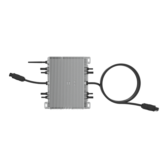
- Page 1 Installation / User Manual Photovoltaic Grid-connected Microinverter(Built-in WIFI-G3) Ver:1.2, 2022-12...
-
Page 2: Table Of Contents
Table of Contents Important Safety Instructions 01-03 Safety Instructions Radio Interference Statement The Meaning of Symbols Microinverter System Introduction 03-05 Microinverters Maximize PV Energy Production More Reliable than Centralized or String Inverters Simple to Install Microinverter Introduction Microinverter System Installation 06-10 Additional Installation Components Required Parts and Tools from You... -
Page 3: Important Safety Instructions
Important Safety Instructions This manual contains important instructions to follow during installation and maintenance of the Photovoltaic Grid-connected Inverter(Microinverter).To reduce the risk of electrical shock and ensure the safe installation and operation of the Microinverter, the following symbols appear throughout this document to indicate dangerous conditions and important safety instructions. -
Page 4: Radio Interference Statement
but maintain the protective earthing conductor in the branch circuit breaker connect to the inverter ,then disconnect the DC inputs. In any circumstance, do not connect DC input when AC connector is unplugged. Please install isolation switching devices on the AC side of the inverter. Radio Interference Statement CE EMC Compliance:The equipment can comply with CE EMC, which are designed to protect against harmful interference in a residential installation. -
Page 5: Microinverter System Introduction
CE mark is attached to the solar inverter to verify that the unit follows the provisions of the European Low Voltage and EMC Directives. Refer to the operating instructions. Person adequately advised or supervised by an electrically skilled person to enable him or her to perceive risks and to avoid hazards which electricity can create. -
Page 6: Microinverters Maximize Pv Energy Production
NOTE: If the wireless signal in the area where the microinverter is weak is weak, it is necessary to add a wifi signal booster at a suitable place between the router and the microinverter. This integrated system improves safety; maximizes solar energy harvest;increases system reliability, and simplifies solar system design, installation,maintenance, and management. -
Page 7: Simple To Install
For more information, please see the Technical Data page (P17~20) of this manual. Model Max. # AC grid Number Per branch SUN1300G3-EU-230 50/60Hz, 230V 4 for 25A breaker SUN1600G3-EU-230 50/60Hz, 230V 4 for 45A breaker SUN1800G3-EU-230 50/60Hz, 230V 3 for 45A breaker SUN2000G3-EU-230 50/60Hz, 230V 3 for 45A breaker - 05 -... -
Page 8: Microinverter System Installation
Microinverter System Installation A PV system using Microinverters is simple to install. Each Microinverter easily mounts on the PV racking, directly beneath the PV module(s). Low voltage DC wires connect from the PV module directly to the Microinverter, eliminating the risk of high DC voltage.Installation MUST comply with local regulations and technical rules. -
Page 9: Parts List
Parts list Please check the following table, to see whether all the parts are included in the package: User manual AC power connectors Microinverter x1 User manual x1 (op�onal) x1 *Antenna for WIFI module x1 * This antenna is for microinverter that has built-in wifi module. Installation Procedures - 07 -... - Page 10 a. Install an appropriate junction box at a suitable location on the PV racking system (typically at the end of a branch of modules). b. Connect the open wire end of the AC cable into the junction box using an appropriate gland or strain relief fitting.
- Page 11 WARNING: Prior to installing any of the microinverters, verify that the utility voltage at the point of common connection matches the voltage rating on microinverter label. WARNING: Do not place the inverters (including DC and AC connectors) where exposed to the sun, rain or snow, even gap between modules.Allow a minimum of 3/4 (1.5cm.) between the roof and the bottom of the Microinverter to allow proper air flow.
-
Page 12: Microinverter System Operating Instructions
NOTE:When plugging in the DC cables, if AC already available,the Microinverter should immediately blink red light and will start work within the setting time (default 60 seconds). If AC is not available,the red light will blink 3 times quickly and repeat after one second until AC is connected. -
Page 13: Troubleshooting
3. The units should start blinking red one minutes after turning on the AC circuit breaker. Then blue led blinking. This means they are producing power normally, the faster blinking of the blue led means more power generated. 4. Configure the internal wifi module according to its user manual. 5. -
Page 14: Troubleshooting A Non-Operating Microinverter
GFDI Error A four time red LED indicates the Microinverter has detected a Ground Fault Detector Interrupter (GFDI) error in the PV system. Unless the GFDI error has been cleared, the LED will remain four times blinking. Other Faults All other faults can be reported to the website and APP. WARNING: Never disconnect the DC wire connectors under load. - Page 15 2. Diagnosing from the network: a. No-Data-Display: The website and APP don't display any data.Check the network configuration. b. Only display microinverter is online but no data.This maybe because server is updating. To troubleshoot a non-operating Microinverter, Follow the steps below in order: 1.
-
Page 16: Replacement
Replacement Follow the procedure to replace a failed Microinverter A. Disconnect the Microinverter from the PV Module, in the order shown below: 1. Disconnect the AC by turning off the branch circuit breaker. 2. Disconnect the AC connector of the microinverter. 3. - Page 17 1300G3/1600G3 Microinverter Datasheet SUN1300G3- SUN1600G3- Model EU-230 EU-230 Input Data (DC) Recommended input power(STC) 210~420W(4 Piece) 210~500W(4 Piece) Maximum input DC voltage MPPT Voltage Range 25~55V MPPT Full Power Voltage Range(V) 30V-55V 33V-55V Min.DC input voltage(V) Max DC short circuit current 19.5Ax4 Max input current 13Ax4...
- Page 18 1800G3/2000G3 Microinverter Datasheet SUN2000G3- SUN1800G3- Model EU-230 EU-230 Input Data (DC) Recommended input power(STC) 210~600W(4 Piece) 210~500W(4 Piece) Maximum input DC voltage MPPT Voltage Range 25~55V MPPT Full Power Voltage Range(V) 40V-55V 36.5V-55V Min.DC input voltage(V) Max DC short circuit current 19.5Ax4...
-
Page 19: Wiring Diagram
Wiring Diagram - 17 -... - Page 20 - 18 -...
-
Page 21: Monitoring Platform
Monitoring Platform This series microinverter has built-in WIFI modular which is able to connect router directly. For WIFI configuration, please check the manual of“Built-in WIFI modular microinverter WIFI configuration Manual” Web monitoring address: ; (for Solarman distributor account) https://pro.solarmanpv.com (for Solarman end user account) https://home.solarmanpv.com For mobile phone monitoring system, scan the QR code to download the APP. -
Page 22: How To Configure The Microinverter To The Router Via Web
How to Configure the Microinverter to the Router Via Web 1. Turn on the wireless network of your PC or smartphone. 2. Select logger network (network name: AP_SN) and connect. The default password is 12345678. Safe Microinverter SN Safe Safe Safe Microinverter SN: 2208314002 Built-in datalogger :1704013242 3. - Page 23 Status Inverter information Help Wizard Inverter serial number Quick Set Firmware version(main) The device can be used as Advanced Firmware version(slave) a wireless access point(AP mode) to facilitata users to Upgrade Inverter model configure the device, or it can also be used as a Rated power Restart wireless information terminal...
- Page 24 Status Help Wizard Quick Set Please fill in the following information: Most systems support the Advanced function of DHCP to obtain IP address automatically. Upgrade Please select disable and Password(8-64 bytes) add it manually if your router Restart (Note: case sensitive) does not support such Show Password function.
- Page 25 Status Help Wizard Setting complete! Quick Set After clicking OK,the system will restart Advanced Click OK, the settings will take effect and the system will immediately. Upgrade restart immediately. Restart If you leave this interface without clicking OK, the settings will Reset be ineffective.
-
Page 26: How To Connect In App
How to connect in APP 1. Registration Open the app of SOLARMAN Smart and register an account. Click "Register" and create your account here. Register English SOLARMAN Smart Phone Number E-mail E-mail Phone Number Username E-mail E-mail Please enter E-mail E-mail Password Verification Code... - Page 27 3. Add a Logger Optional 1: Enter the logger SN manually. Optional 2: Click the icon in the right and scan the QR code to enter logger SN. You can find logger SN on the carton packaging or on the logger body. MY Plants Logger hinzufugen Create a Plant...
- Page 28 Step 1:Confirm Wi-Fi Info Please make sure your phone has connected to the right WiFi network. And click "Start to configure". Notice: 5G WiFi is not supported . Special characters (e.g. ,;‘’ =” ” `) in router name and password are not supported. SN:2312423 Password App_only...
- Page 29 WLAN settings Go to WLAN Setting and connect the following network manually WLAN Android MY NETWORKS ChinaNet AP_622602179 AP_622602179 Android HYH123 IGWN-5G ChinaNet IGWN-HILINK AP_622602179 HYH123 AP_622602179 IGWN-5G Password OTHER NETWORKS Show advanced options act-blue ChinaNet-igen Step 3:Auto Configuration Please wait for a while to complete the configuration. Then system will turn to the following page.
- Page 30 Device Configuration Configurtion succeeded Device data will be displayed in 10 mins. After that, Please shorten the distance between the device, you can check device status in device list. router and phone. Connect to device Configuring Restart Verified Done - 28 -...
Need help?
Do you have a question about the SUN2000G3 and is the answer not in the manual?
Questions and answers