
Related Manuals for Deye SUN-23K-G03-LV


Summary of Contents for Deye SUN-23K-G03-LV
- Page 1 Grid-connected PV Inverter SUN-��K-G��-LV SUN-20K-G02-LV SUN-��K-G��-LV SUN-23K-G03-LV SUN-25K-G03-LV User Manual SUN-30K-G03-LV...
- Page 2 �. Introduction ………………………………………………………… - � - �.� Appearance Introduction …………………………………………………… - � - �.� Parts list ……………………………………………………………… - � - �. Safety warnings and instructions ……………………………………… - � - �.� Safety signs ………………………………………………… - � - �.� Safety instructions ………………………………………………… - �...
- Page 3 �. Zero-export function via energy meter …………………………… - �� - �.� Multiple strings and parallel connection meters ……………………… - �� - �.� How to browse the load power of your PV grid-tieplant on monitoring platform? - �� - �. General Operation ……………………………………………...
-
Page 4: About This Manual
Documents must be stored carefully and be available at all times. Contents may be periodically updated or revised due to product development. The information in this manual is subject to The latest manual can be acquired via service@deye.com.cn change without notice. �. Introduction �.�... - Page 5 �.� Parts list Please check the following table, to see whether all the parts are included in the package: Mounting stainless steel screws M��� Grid-tied PV String Inverter Wall mounting bracket x � x �� x � DC+/DC- Plug connectors Stainless steel anti-collision including metal terminal bolt M����...
- Page 6 �. Safety warnings and instructions Improper use may result in potential electric shock hazards or burns. This manual contains important instructions that should be followed during installation and maintenance. Please read these instructions carefully before use and keep them for future reference. �.�...
- Page 7 Shock Hazard: When PV module is exposed to sunlight, the output will generate DC voltage. Prohibit touching to avoid shock hazard. Shock Hazard: While disconnect the input and output of the inverter for maintenance, please waits for at least � mins until the inverter discharge the remnant electricity. High Temperature Hazard: Local temperature of inverter may exceed ��℃...
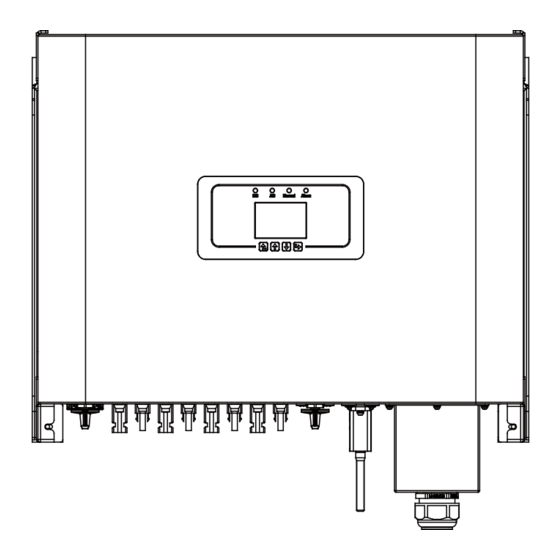
- Page 8 �. Operation Interface �.� Interface View Normal Alarm Pic �.� Front panel display �.� Status Indicator The inverter panel has � indicators, the left one is dc output indicators, green indicates normal DC input. Beside is the AC indicator, green indicating normal ac connection. Beside the AC indicator is the operating indicator, green indicating normal output.
- Page 9 �.� Buttons There are four buttons on the inverter panel:Above is Up and increase button(UP), Below is down and decrease button(DOWN), Left is ESC button(ESC), Right is Enter button(ENTER). Achieving below functions by the four buttons: Page turning (use UP and DOWN button) ●...
- Page 10 �. Product installation �.� Select installation location To select a location for the inverter, the following criteria should be considered: WARNING: Risk of fire Do not install the inverter in areas containing highly flammable materials or gases. ● Do not install the inverter in potentially explosive atmospheres. ●...
- Page 11 Install on a wall or strong structure capable of bearing the weight. ● Install vertically with a maximum incline of +/-��°. If the mounted inverter is tilted to an ● angle greater than the maximum noted, heat dissipation can be inhibited, and may result in less than expected output power.
- Page 12 ≥500mm ≥500mm Pic �.� Installation Gap �.� Mounting bracket of inverter Pic �.� Mounting bracket dimensions - �� -...
- Page 13 �.� Inverter Installation The inverter should be mounted in a vertical position. The steps of mounting are as follows �. For brick walls, the position of the holes should be suitable for the expansion bolts. �. Make sure the bracket is horizontal and the mounting holes are in the correct points. Drilling the holes on the wall according the marks.
- Page 14 � Electrical Connection �.� DC input terminal connection �. Switch the Grid Supply Main Switch(AC)OFF. �. Switch the DC lsolator OFF. �. Assemble PV input connector to the inverter. Warning: When using PV modules, please ensure the PV+ & PV- of solar panel is not connected to the system ground bar.
- Page 15 The steps to assemble the DC connectors are listed as follows: a) Strip off the DC wire about �mm, disassemble the connector cap nut (see picture �.�). Pic �.� Disassemble the connector cap nut b) Crimping metal terminals with crimping pliers as shown in picture �.�. Pic �.�...
- Page 16 Please use its own DC power connector from the inverter accessories. Do not interconnect the connectors of different manufacturers.Max. DC input current should be ��A. if exceeds, it may damage the inverter and it is not covered by Deye warranty. �.� AC terminal connection Copper core cable Cable specifications...
- Page 17 AC wire production method is the same as that of �.�.�. AC wire installation method: �) Remove the � fixing screws on the AC junction box of the inverter as shown in Pic �.�. After removing the junction box, you can see the terminals of the inverter. The default is � digits as shown in Pic �.�.
- Page 18 �) Screw the AC connection cover back to the shell and tighten all the screws to tighten the waterproof protection connector, as shown in Pic �.�� Pic �.�� Tighten the AC junction box �.�.� Recommended current protector specifications Inverter Rated voltage Rated output power(KW)...
- Page 19 �.� Connection of the ground line Good grounded is important for resist the surge voltage shock and improve EMI's performance. So before the connection of AC, DC, communication connections, inverter needs to ground first. For a single system, just ground the PE cable; For multiple machine systems, all PE cables of the inverter need to be connected to the same grounding copper platoon to ensure the equipotent connection.
- Page 20 Phone GPRS Router Web Server WIFI Pic �.�� Internet monitoring solution �.�.� Installation of datalogger When installing the WiFi stick, tear off the sealing strip on the inverter. Insert the datalogger into the interface and fix it with a screw. The configuration of the datalogger needs to be performed after various electrical connections have been completed and the inverter DC power on.
- Page 21 �.�.� Configuration of datalogger For the configuration of datalogger, please refer to illustrations of the datalogger. �. Start up and Shut off Ensure that the inverter meets the following conditions before starting the inverter, otherwise it may cause fire or damage to the inverter without quality assurance, at the same time the situation on our company does not undertake any responsibility.
- Page 22 �. Zero-export function via energy meter There're four kinds of energy meters for this series inverter. First type is Eastron SDM���-Mod- bus V� which is able to measure the Max. ���A current directly. More details please refer to Pic �.� & �.�. For the Eastron SDM��� MCT ��mA, it needs external CT to measure the current. The CT power range is from �A-����A.
- Page 23 1 2 3 4 5 6 7 8 Eastron (�,�,�,�) (�,�,�,�) B A G RS ��� RS ��� B RS ��� A Eastron SDM���-Modbus V� Pic �.� Eastron meter Inverter Solar Panel array limiter1 limiter2 AC Breaker for grid port SUN-��K-G��-LV:���A AC breaker SUN-��K-G��-LV: ���A AC breaker AC Breaker...
- Page 24 1 2 3 4 5 6 7 8 Eastron (�,�,�,�) (�,�,�,�) B A G RS ��� RS ��� B RS ��� A Eastron SDM���-Modbus V� Pic �.� Eastron meter Inverter Solar Panel array limiter1 limiter2 AC Breaker for gen port SUN-��K-G��-LV:���A AC breaker SUN-��K-G��-LV: ���A AC breaker AC Breaker...
- Page 25 9 1 0 11 1 2 1 3 1 4 1 5 1 6 1 7 1 8 1 9 2 0 Eastron 1 2 3 4 15 16 17 18 19 20 Grid voltage Auxiliary Current inputs sampling power supply ��...
- Page 26 9 1 0 11 1 2 1 3 1 4 1 5 1 6 1 7 1 8 1 9 2 0 Eastron 1 2 3 4 15 16 17 18 19 20 Grid voltage Auxiliary Current inputs sampling power supply ��...
- Page 27 (�,�,�,��) (�,�,�,��) Three-Phase Smart Meter RS ��� CHNT DTSU��� Pic �.� CHNT meter Inverter Solar Panel array limiter1 limiter2 AC Breaker for grid port SUN-��K-G��-LV:���A AC breaker SUN-��K-G��-LV: ���A AC breaker AC Breaker RS ��� Male connector Home load L� L� L� N VCC_�V ���_B RS ���...
- Page 28 (�,�,�,��) (�,�,�,��) Three-Phase Smart Meter RS ��� CHNT DTSU��� Pic �.�� CHNT meter Inverter Solar Panel array AC Breaker for gen port limiter1 limiter2 SUN-��K-G��-LV:���A AC breaker SUN-��K-G��-LV: ���A AC breaker AC Breaker RS ��� Male connector L� L� L� N Home load VCC_�V ���_B...
- Page 29 6 9 10 1314 16171921 Three-Phase Smart Meter 230/400V, 3~100A/40mA 50/60Hz 24 25 Phase A current =5.000A 13 14 16 17 19 21 RS485 CHNT DTSU��� Phase B current =5.001A �x���/���V Phase C current =�.���A ���A/��mA Pic �.�� CHINT meter Inverter Solar Panel array AC Breaker for grid port...
- Page 30 6 9 10 1314 16171921 Three-Phase Smart Meter 230/400V, 3~100A/40mA 50/60Hz 24 25 Phase A current =�.���A 13 14 16 17 19 21 RS485 CHNT DTSU��� Phase B current =�.���A �x���/���V Phase C current =�.���A Pic �.�� CHINT meter Inverter Solar Panel array AC Breaker for gen port limiter1 limiter2...
- Page 31 �. Press Enter button on the LCD panel in the main interface into the menu options, select [parameter setting] to enter setup submenu, and then select [run param], at this time please input the default password ���� through pressing the button [up down, enter], enter the operation parameter setting interface, shown as picture �.��.
-
Page 32: Menu Setting
�.� Multiple strings and parallel connection meters This application is that when the string inverters work in parallel, there is only one power grid and one load, and only one meter can be connected to prevent reverse current, so only this many-to-one anti-reverse current connection can be connected. - Page 33 Name Description Range AVG: Average power of three phase is zero exported. AVG/MIN Exp_Mode MIN: Phase with minimum load power is zero exported, while the other two phase may be in purchase mode. CT ratio of power grid side meter when extern �-����...
- Page 34 1 2 3 4 5 6 7 8 Eastron (�,�,�,�) (5,6,7,8) B A G RS 485 RS 485 B RS 485 A Eastron SDM���-Modbus V� Pic �.�� Eastron meter Master(Mst) Grid L� L� L� N RS��� 485_B 485_A L� VCC_�V ���_B RS ���...
- Page 35 1 2 3 4 5 6 7 8 Eastron (�,�,�,�) (5,6,7,8) B A G RS 485 RS 485 B RS 485 A Eastron SDM���-Modbus V� Pic �.�� Eastron meter Generator Master(Mst) L� L� L� N RS��� 485_B 485_A L� VCC_�V ���_B RS ���...
- Page 36 9 1 0 11 1 2 1 3 1 4 1 5 1 6 1 7 1 8 1 9 2 0 Eastron 1 2 3 4 15 16 17 18 19 20 Grid voltage Auxiliary Current inputs sampling power supply ��...
- Page 37 9 1 0 11 1 2 1 3 1 4 1 5 1 6 1 7 1 8 1 9 2 0 Eastron 1 2 3 4 15 16 17 18 19 20 Grid voltage Auxiliary Current inputs sampling power supply ��...
- Page 38 (�,�,�,��) (�,�,�,��) Three-Phase Smart Meter RS ��� CHNT DTSU��� Pic �.�� CHNT meter Master(Mst) AC Breaker L� L� limiter1 limiter2 L� Slave�(Slv�) Solar Panel array AC Breaker L� L� limiter1 limiter2 L� Slave�(Slv�) Solar Panel array AC Breaker L� L� limiter1 limiter2 L�...
- Page 39 (�,�,�,��) (�,�,�,��) Three-Phase Smart Meter RS ��� CHNT DTSU��� Pic �.�� CHNT meter Master(Mst) AC Breaker L� L� limiter1 limiter2 L� Solar Panel array Slave�(Slv�) AC Breaker L� L� L� limiter1 limiter2 Slave�(Slv�) Solar Panel array AC Breaker L� L� L�...
- Page 40 6 9 10 1314 16171921 Three-Phase Smart Meter 230/400V, 3~100A/40mA 50/60Hz 24 25 Phase A current =5.000A 13 14 16 17 19 21 RS485 CHNT DTSU��� Phase B current =5.001A �x���/���V Phase C current =5.002A Pic �.�� CHINT meter Master(Mst) AC Breaker L�...
- Page 41 6 9 10 1314 16171921 Three-Phase Smart Meter 230/400V, 3~100A/40mA 50/60Hz 24 25 Phase A current =5.000A 13 14 16 17 19 21 RS485 CHNT DTSU��� Phase B current =5.001A �x���/���V Phase C current =5.002A Pic �.�� CHINT meter Master(Mst) AC Breaker L�...
- Page 42 �.� How to browse the load power of your PV grid-tie plant on monitoring platform? If you want to browse load power of the system and how much energy (KWH) does it export to grid(inverter output power is used to power the load firstly and then the surplus energy will feed into grid).
- Page 43 Secondly, go to plant page, if it shows the PV power, load power and grid power, which means the configuration is correct. String inverter Solar Station Back to Plants list ID����� Compare Edit More Partially Offline No Alerts Last update ����/��/�� ��:��:�� UTC+��:�� String inverter Solar Sta...
- Page 44 �. General Operation During normal operation, the LCD shows the current status of the inverter, including the current power, total generation, a bar chart of power operation and inverter ID, etc. Press the Up key and the Down key to see the current DC voltage, DC current, AC voltage, AC current, inverter radiator temperature, software version number and Wifi...
- Page 45 P�-P� Q�-Q� Cut-In Back Cut-Out P�-P� PF�-PF� start Time stop RmpTime PtUsed ActiveP Curve Q-Mode ReactP Exp_Mode Fun- ISO CT_Ratio � AUTO ACREL Fun RCD EASTRON FeedIn CHNT SelfCheck Shunt ShuntQTY Island Generator G.CT AUTO Meter G.MFR ACREL EASTRON G.FeedIn Limiter Setup CHNT...
- Page 46 INMETRO EN����� EN����� IEC����� CUSTOM VDE_���� UTE_C�� RD���� CEI_�_�� G��_G�� AS����(.�) NB/T ����� GridStanderd Protect Param OV_�-OV_� ���.�V Advanced Tov_�-Tov_� ����ms UV_�-UV_� Back ���.�V Tuv_�-Tuv_� ����ms OF_�-OF_� ��.��HZ ����ms Setup Tof_�-Tof_� ��.��HZ UF_�-UF_� Tuf_�-Tuf_� ����ms Vrc_H Vrc_L Frc_H Frc_L VGrid ���/���V OV��Min Address:��...
- Page 47 �.� The initial interface From the initial interface, you can check power, daily generation, gross generation, invertert ID , model and time. �.�Kw SN-�� ����-��-�� ��:��:�� P - �� Kw Power: ��.��Kw Day : ���kWh Total : �� MWh State : Standby �...
- Page 48 Grid Ua : ���.�V Ia : �.�A Grid Freq : ��.��Hz PF : �.��� Pic �.� AC running state information You can check the three phase voltage, current, and grid frequency. Total DC Power: �.���W Lcd���� Inv���� Pic �.� Inverter firmware version You can check the inverter LCD software Ver����...
- Page 49 �.�.� Main Menu There are four submenu in the Main Menu. MENU Statistics 《 Fault Record ON/OFF Setup Pic �.� Main Menu �.� Statistics information There are five submenu in the statistics. MENU》 Statistics E-Day E-History E-Month Test Data 《 E-Year Pic �.�...
- Page 50 MENU》 Statistics》 E-Day <����-��-��> ��MWh � � �� �� �� Pic �.� E-Day MENU》 Statistics》 E-Month ����-�� �-�� �� �� <> ��MWh �� �� �� �� �� �� �� �� �� �� Pic �.� E-Month MENU》 Statistics》 E-Year <����> ���KWh ��...
- Page 51 MENU》 Statistics》 E-History <����-����> �KWh �� �� �� �� �� �� �� �� �� �� Pic �.�� E-History This information is for technician’s reference. PV� ����� �k� ����� ���� PV� ����� �k� ����� ��� : ���� ����� �k� ����� ��� ����...
- Page 52 �.� ON/OFF setting MENU》 ON/OFF Turn ON Turn OFF 《 Pic �.�� ON/OFF setting Into each submenu through cursor. MENU》 ON/OFF》 Turn ON 《 Turn ON Cancel Pic �.�� ON set MENU》 ON/OFF》 Turn OFF 《 Turn OFF Cancel Pic �.�� OFF set - ��...
-
Page 53: Menu Setup
�.� Parameter setting Setting includes system param, run param, protect param, comm.. param. All of these information for maintenance reference. MENU》 Setup System Param 《 Param Protect Param Comm. Param Pic �.�� Setting �.�.� System Param System Param MENU》 Setup 》 Time Set Language Set Display Set... - Page 54 �.�.�.� Time Set Time Set ����-��-�� ��:��:�� Cancel Pic �.�� System Param �.�.�.� Language Set Lauguage Set 简体中文 English 《 Polski Pic �.�� Lauguage set �.�.�.� Display Set Display Set Brightness Keep 《 Delay time ��S Cancel Pic �.�� Display set - ��...
-
Page 55: Factory Data Reset
�.�.�.� Factory data reset Factory data reset Confirm to reset 《 Cancel Pic �.�� Factory data reset set �.�.�.� Setting Restore Setting Restore Confirm to restore 《 Cancel Pic �.�� Factory data reset set Warning: Password required-- only for access-authorized engineer. Un-authorized access may avoid the warranty. - Page 56 �.�.� Run Param PassWord * * * * Pic �.�� Password MENU》 Setup》 Run Param ActiveP ��% SelfCheck ��S QMode Island ReactP �.�% Meter �.��� Limiter Fun_ISO Feed_In �% Fun_RCD OFF MPPT Num � Cancel - �� -...
- Page 57 Name Description Range 0-110% Adjust the output active power in % ActiveP OFF/Q(P)/PF(P) QMode Multiple reactive power control modes /Q(U)/PF/PER ReactP -100%-+100% Adjust reactive power output in % -1-0.8~+0.8-1 Power Fator Fun_ISO ON/OFF Insulation resistance detection Fun_RCD ON/OFF Residual current detection Self-check 0-1000s Inverter's self-check time.The default value 60s...
- Page 58 MENU》 Setup》 Run Param Vref �.�V OFDerate PowerLimit UFUprate VoltageRT WGra �.�% Sunspec WGraStr �.�% Cancel Name Description Range ON/OFF/Clear Arc-fault detection function OFDerate 0-100% Pmax/Hz Active power response to over frequency UFUprate 0-100% Pmax/Hz Active power response to under frequency ON/OFF power response to grid voltage deviation WGra...
-
Page 59: Power Limit
MENU》 Setup》 Run Param Vref �.�V OFDerate PowerLimit UFUprate VoltageRT WGra �.�% Sunspec Sunspec Cancel Voltage Ride Through HVRT OFF LVRT Vstart �.�% Vstart �.�% Vstop �.�% Vstop �.�% ZVRT Cancel Pic �.�� Voltage Ride Through - �� -... - Page 60 �.�.�.� Over-frequency Response This series inverter provides “over-frequency response” function. Long pressing the “OFD Derate” to enter the “over-frequency response” setting menu. MENU》 Setup》 Run Param Vref ���.�V OFDerate ON PowerLimit UFUprate OFF VoltageRT Sunspec WGra ��.�% Sunspec Cancel Definition of Over- frequency Response Parameters Description Parameter Range...
- Page 61 When the frequency exceeds StopPoint: ��.�Hz, the inverter output should stop (ie � W). When the frequency is lower than StopPoint: ��.� Hz, the inverter will linearly increase the power output with a gradient of ���% Pmax/Hz until it reaches StopPoint: ��.� Hz. In the hysteresis mode, when the frequency is lower than StopPoint: ��.�...
- Page 62 “Q(U)” Mode QU Setting Start ��.�% Stop ��.�% RmpTime �s PtUsed � Uref Curve UrfTime Back QU Setting V� ��.�% Q� -��.�% V� ��.�% Q� �.�% V� ���.�% Q� �.�% V� ���.�% Q� ��.�% V� ���.�% Q� ��.�% V� ���.�% Q�...
- Page 63 Parameter Range Description The QU mode starts when the active power Start 0%-130% Rate out power is greater than this value The QU mode stops when the active power 0%-130% Rate out power Stop is less than this value Increase or decrease the time required for RMpTime 0-1000s the reactive power to reach the specified...
- Page 64 “Q(P)” Mode The reactive power output by the inverter is controlled by the active power of the inverter. Upper Q/Pn lnd (P�,Q�) P�(P�,Q�) P/Pn P�(P�,Q�) P�(P�,Q�) P�(P�,Q�) Lower P�(P�,Q�) Q/Pn Cap Pic �.�� Reactive Power Regulation Curve in Q(P) Mode MENU》...
- Page 65 Parameter Range Descrption Value of Q/Pn at point (P1,Q1) on the Q(P) mode 0%-100% Pn curve Reactive power value at point (P1,Q1) on the Q(P) -60% -60% Q/Pn mode curve Value of Q/Pn at point (P2,Q2) on the Q(P) mode 0%-100% Pn curve Reactive power value at point (P2,Q2) on the Q(P)
- Page 66 PU Setting U� �.�% P� �.�% U� �.�% P� �.�% U� �.�% P� �.�% U� �.�% P� �.�% RmpTime �S Back U/Vref (U�,P�) (U�,P�) (U�,P�) (U�,P�) P/Pn Pic �.�� Active Power Regulation Curve in PU Curve Parameter Range Description Value of P/Pn at point (P1,U1) on the PU mode 0%-110% Pn curve Grid voltage limit at point (P1,U1) on the PU mode...
- Page 67 “PF(P)” Mode PFP Setting Cut_in �.�% Cut_out �.�% P� �.�% PF� -�.��� P� �.�% PF� -�.��� P� �.�% PF� -�.��� PF� -�.��� P� �.�% P� �.�% PF� -�.��� Back PFP Setting P� �.�% PF� -�.��� Time �s Back P�(P�,PF�) lagging P�(P�,PF�) P�(P�,PF�) P/Pn...
- Page 68 Parameter Range Description Power value at point (PF1,P1) on the PF(P) 0-110% Pn Curve PF value at point (PF1,P1) on the PF(P) 0.8 leading - 0.8 lagging Curve Power value at point (PF2,P2) on the PF(P) 0-110% Pn Curve PF value at point (P2,PF2) on the PF(P) 0.8 leading - 0.8 lagging Curve Power value at point (P3,PF3) on the PF(P)
- Page 69 �.�.� Protect Param MENU》 Setup》 Protect Param GridStandard 《 Advanced Cancel Pic �.�� Protect Param Warning: Engineer only. Standard Brazil EN�����-�-PL EN�����-� IEC����� Custom 《 VDE���� Cancel Standard VDE���� Spain CEI � �� 《 G�� G�� NBT�����-B Cancel - �� -...
- Page 70 Standard Australia-A Australia-B Australia-C 《 New Zealand Cancel Standard Norway Switerland R�� 《 CEI-��� Cancel Pic �.�� “Standard” - VoltageTriping Tov_� ����ms OV_� ���.�V Tov_� ����ms OV_� ���.�V OV_� ���.�V Tov_� ����ms UV_� ���.�V Tuv_� ����ms Tuv_� ����ms UV_� ���.�V Tuv_�...
- Page 71 - FrequencyTriping Tof_� ����ms OF_� ��.��Hz Tof_� ����ms OF_� ��.��Hz OF_� ��.��Hz Tof_� ����ms Tuf_� ����ms UF_� ��.��Hz Tuf_� ����ms UF_� ��.��Hz Tuf_� ����ms UF_� ��.��Hz Cancel - Miscellaneous �.�% Vrc_H �.�V Vrc_L �.�V Frc_H �.�Hz Frc_L �.�Hz VGrid ���/���V OV��Min Cancel Pic �.��...
- Page 72 �. Repair and Maintenance String type inverter doesn’t need regular maintenance. However, debris or dust will affect heat sink’s thermal performance. It is better to clean it with a soft brush. If the surface is too dirty and affect the reading of LCD and LED lamp, you can use wet cloth to clean it up. High Temperature Hazard: When the device is running, the local temperature is too high and the touch can cause burns.
-
Page 73: Error Code
Check the solar panel output connection. F�� Failure in reading memory (EEPROM). Restart the inverter if the Read the memory error fault still exists, contact your installer or Deye service. F�� Failure in writing memory (EEPROM). Restart the inverter if the Write the memory error fault still exists, contact your installer or Deye service. - Page 74 1. Check whether the 'BUSN' cable or driver board power supply F�� cable is loose. The DC busbar is unbalanced 2. Restart the inverter, if the fault still exists, contact your installer or Deye service. F�� DC end insulation error Hardly appear the code. Never ever happened so far. F��...
- Page 75 1. Check AC current sensor and its circuit. AC over current(one cycle) 2. Restart the inverter, if the fault still exists, contact your installer or Deye service. F�� DC over current Hardly appear the code. Never ever happened so far.
- Page 76 Error code Description Ongrid - Three Phase F�� AC grid V over current Hardly appear the code. Never ever happened so far. F�� AC grid W over current Hardly appear the code. Never ever happened so far. F�� Reactor A phase over current Hardly appear the code.
- Page 77 ��.Specification Model SUN-��K-G��-LV SUN-��K-G��-LV Input Side Max.DC Power(kW) ��.� kW �� kW Max.DC Input Voltage(V) ���V Start-up DC Input Voltage(V) ���V MPPT Operating Range(V) ���V~���V Rated DC input voltage(V) ���V MPPT Full Power Voltage Range(V) ���V-���V Max.DC Input Current(A) ��A+��A+��A ��A+��A+��A+��A Max.
-
Page 78: General Data
General Data DC Connection MC-� mateable AC Connection IP�� rated plug Display LCD ��� × ��� Interface RS���/RS���/Wifi/LAN ����-��-�� Ver: �.� - �� -... - Page 79 Add: No.�� South YongJiang Road, Daqi, Beilun, NingBo, China. Tel: +�� (�) ��� ���� ���� Fax: +�� (�) ��� ���� ���� E-mail: service@deye.com.cn Web: www.deyeinverter.com...
Need help?
Do you have a question about the SUN-23K-G03-LV and is the answer not in the manual?
Questions and answers