Table of Contents
Advertisement
Quick Links
Advertisement
Table of Contents

Subscribe to Our Youtube Channel
Related Manuals for Ford FG11050PBECO


Summary of Contents for Ford FG11050PBECO
- Page 1 MODEL#: FG11050PBECO Generator OPERATOR’S MANUAL www.fordpower.cc...
-
Page 2: Table Of Contents
TABLE OF CONTENTS Introduction.....................................3 Product Specifications..............................3 Parts Ordering / Customer Service..........................3 Safety Rules....................................4 Safety Symbols................................4 Safety Instructions ..............................4 Features....................................7 Assembly ....................................9 Unpacking ..................................9 Packing List ................................9 Remove Shipping Bracket ............................10 Attaching Wheels ..............................1 0 Installing support leg .............................. -
Page 3: Introduction
INTRODUCTION Thank you for purchasing this superior quality portable generator from Ford Power Equipment. When operating and maintaining this product as instructed in this manual, your generator will give you many years of reliable service. Product Specifications: This generator is an engine-driven, revolving field, alternating current (AC) portable generator. It is designed to supply electrical power to operate tools, appliances, camping equipment, lighting, or serve as a back up power source during power outages. -
Page 4: Safety Rules
SAFETY RULES Safety Symbols Indicates a potentially hazardous WARNING! situation which could result in serious injury or death if not avoided. Indicates a potentially hazardous CAUTION! situation which could result in damage to equipment or property. Toxic Fumes Risk of fire Risk of explosion Risk of electric shock Hot surface... - Page 5 SAFETY RULES WARNING! Never exceed generator’s wattage / amperage capacity. This could damage the generator and / or connected electrical devices. Check operating voltage and frequency requirements of all electrical devices prior to plugging them into the generator. • WARNING! Never start or stop engine with electrical devices plugged in to the receptacles.
- Page 6 • Never insert objects through cooling slots. WARNING! Never operate this unit if there are any broken or missing parts and only use Ford Power Equipment replacement parts specifically designed for this unit. • Improper treatment of generator can damage the unit and shorten it’s life.
-
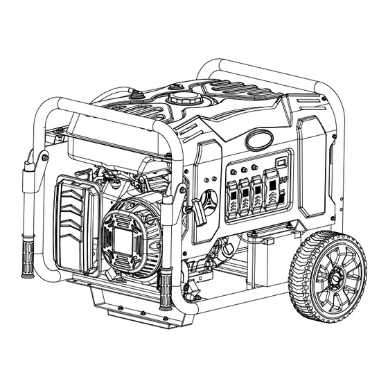
Page 7: Features
FEATURES A - CIRCUIT PROTECTORS E - 120 / 240 VOLT AC, 50 AMP RV OUTLET(NEMA14-50). B - HOUR METER F - 120/240 VOLT AC, 30 AMP TWIST LOCK RECEPTACLE (NEMA L14-30R). C - MAIN CIRCUIT BREAKER G - TWO 120 V GFCI DUPLEX RECEPTACLES. W - FUEL SELECTOR SWITCH D - START/ON/OFF SWITCH... - Page 8 FEATURES P - FUEL TANK H - FUEL GAUGE Q - FUEL FILL CAP I - FUEL TANK VAPOR VENT R - FUEL VALVE (ON/OFF) J - GENERATOR FRAME S - RECOIL STARTER GRIP K - CHOKE LEVER T - OIL FILL (DIPSTICK) L - AIR FILTER U - BATTERY M - HANDLES &...
-
Page 9: Assembly
ASSEMBLY Unpacking 1. Place box on a level surface. 2. Remove all items from box except the generator. Make sure all items listed on the packing list are included and not damaged. 3. Cut down the sides of box being careful to avoid hitting the generator. 4. -
Page 10: Remove Shipping Bracket
ASSEMBLY Remove Shipping Bracket (See fig 1) • Remove and discard the two RED shipping brackets and mounting hardware before starting the Generator. Attaching Wheels (See fig 2) • Parts needed - 2 wheels, 2 axles, 2 hair pins, 2 washers, 2 hub caps and 2 self-tapping screws. •... -
Page 11: Attaching Battery Cable
ASSEMBLY Attaching Battery Cable (See fig 4) • Parts needed - Black and Red battery cable • The Red (+) Connector should be attached to the battery first. • Remove the screw from the battery terminal. • Place the screw through the eyelet and tighten the screw and make sure the terminal will not touch any part of the frame. •... -
Page 12: Adding Oil/Checking Engine Oil
ASSEMBLY DANGER/POISON NON-SPILLABLE FLUSH EYES SEALED BATTERY IMMEDIATLEY WITH WATER This is a ready filled, SHIELD activated sealed battery. SULFURIC EYES. Never remove strip. EXPLOSIVE ACID MEDICAL SPARKS Refer to owner’s manual GASES CAN CAN CAUSE HELP FLAMES CAUSE BLINDNESS or instruction sheet for BLINDNESS OR FAST... -
Page 13: Adding Fuel
ASSEMBLY Adding Fuel (See fig 8) • Set generator on a clean and level surface in an area that is well ventilated. • Remove fuel cap. • Insert a funnel into the fuel tank and carefully pour gasoline into the tank until fuel level reaches 1 ½ inches below the top of the neck. -
Page 14: Operation
OPERATION Grounding the Generator (See fig 9) The ground terminal located on the back of the generator frame must always be used to connect generator to a driven ground rod. Connect the ground terminal to the driven ground rod with a No 8 AWG (American Wire Gauge) copper wire. The wire connects to the terminal between the lock washer and nut. -
Page 15: How To Stop Engine
OPERATION WARNING! Never start or stop engine with electrical devices plugged in to the receptacles. Failure to do so could damage the generator and / or connected electrical devices. • Always start the engine and let it stabilize before connecting any electronic devices. •... -
Page 16: Extension Cord Selection
OPERATION CAUTION! Do not connect 3-phase loads to generator. Extension Cord Selection Refer to the below table to ensure the extension cord used has the capacity to carry the required load. If the size of the cable is inadequate it can cause a voltage drop, which can damage the electrical device and cord. Load (Watts) Current Maximum Cord Length... -
Page 17: Wattage Reference Guide
OPERATION Wattage Reference Guide (Wattages listed are just approximations. Check electronic device for actual wattage) Essentials Rated Watts Surge Watts Bathroom Rated Watts Surge Watts 75W Light Bulbs 75 each 75 each Hair Dryer 1250 18 CU Ft Refrigerator / Freezer 2200 Curling Iron 1500... -
Page 18: Power Management
OPERATION Hour Meter (See Fig 20) The digital hour meter operates whenever the engine is running and keeps track of how many hours the unit has been used. Use this meter along with the manual to determine when and what type of service on the unit is needed. The display will show the word “LUBE”... -
Page 19: Maintenance
MAINTENANCE Creating a Temporary Cold Weather Shelter In an emergency, the original shipping carton can be used as a temporary shelter. The shelter should hold enough heat created by the generator to prevent icing. Cut off all flaps. Cut off one of the long sides of the carton to expose the units muffler and exhaust. Do not enclose the muffler / exhaust side of the generator. -
Page 20: Changing Oil
MAINTENANCE Changing Oil (See Fig 21) • Run the Generator until the Engine is warm. • Place generator on a level surface. • Remove the crankcase dipstick. • Place an oil pan underneath the oil drainage bolt to collect used oil. Oil Fill &... -
Page 21: Cooling System
MAINTENANCE CAUTION! Used oil should be disposed of at an approved disposal site. See your local oil retailer for more information. Air Filter (See Fig 22) A dirty air filter will reduce the life span of the engine, make it difficult to start the engine, and reduce the unit’s performance. •... -
Page 22: Carburetor Adjustment
MAINTENANCE Carburetor Adjustment The carburetor is low emission and is equipped with a non-adjustable idle mixture valve. If adjustment is needed contact an authorized dealer. Replacing Fuel Filter (See Fig 25) Occasionally the fuel filter may become clogged and need replacing. To purchase a replacement fuel filter contact customer service or your local small Engine repair shop. -
Page 23: How To Store
MAINTENANCE Draining the carburetor • Turn the engine OFF. • Turn the fuel valve to the OFF position. • Position a suitable container under the carburetor drain screw to catch fuel; loosen the screw. • Allow fuel to drain completely into container. •... - Page 24 CO SENSOR CO SENSOR The CO Sensor monitors for the accumulation of poisonous carbon monoxide gas around the generator when the engine is running. If increasing levels of CO gas are detected, the CO Sensor automatically shuts down the engine. The CO Sensor will also detect the accumulation of carbon monoxide from other fuel burning sources used in the area of operation.
-
Page 25: Troubleshooting
TROUBLESHOOTING Problem Cause Solution Engine is running, but AC output is not 1. Open circuit breaker 1. Reset circuit breaker available 2. Poor connection 2. Check and repair 3. Defective cord set 3. Check and repair 4. Connected device is faulty 4. -
Page 26: Diagrams
DIAGRAMS...
Need help?
Do you have a question about the FG11050PBECO and is the answer not in the manual?
Questions and answers