Table of Contents
Advertisement
Available languages
Available languages
Quick Links
Advertisement
Chapters
Table of Contents

Related Manuals for Ford FG5250PBE


Summary of Contents for Ford FG5250PBE
- Page 1 MODEL#:FG5250PBE ITEM#: F2E425E991 Generator OPERATOR’S MANUAL Warning: The Engine Exhaust from this product contains chemicals known to the State of California to cause cancer, birth defects or other reproductive harm. www.fordpower.cc...
-
Page 2: Table Of Contents
TABLE OF CONTENTS Introduction..................................... 3 Product Specifications..............................3 Parts Ordering / Customer Service..........................3 Safety Rules.................................... 4 Safety Symbols................................4 Safety Instructions............................... 4 Features....................................7 Assembly ....................................9 Unpacking ..................................9 Packing List ................................9 Remove Shipping Bracket ............................10 Attaching Wheels ..............................1 0 Installing support leg .............................. -
Page 3: Introduction
INTRODUCTION Thank you for purchasing this superior quality portable generator from Ford Power Equipment. When operating and maintaining this product as instructed in this manual, your generator will give you many years of reliable service. Product Specifications: This generator is an engine-driven, revolving field, alternating current (AC) portable generator. It is designed to supply electrical power to operate tools, appliances, camping equipment, lighting, or serve as a back up power source during power outages. -
Page 4: Safety Rules
SAFETY RULES Safety Symbols Indicates a potentially hazardous WARNING! situation which could result in serious injury or death if not avoided. Indicates a potentially hazardous CAUTION! situation which could result in damage to equipment or property. Toxic Fumes Risk of fire Risk of explosion Risk of electric shock Hot surface... - Page 5 SAFETY RULES Never exceed generator’s wattage / amperage capacity. This could damage the generator WARNING! and / or connected electrical devices. Check operating voltage and frequency requirements of all electrical devices prior to plugging them into the generator. • Never start or stop engine with electrical devices plugged in to the receptacles. Failure to do WARNING! so could damage the generator and / or connected electrical devices.
- Page 6 Never transport or make adjustments to this unit while it is running. • Never insert objects through cooling slots. Never operate this unit if there are any broken or missing parts and only use Ford Power WARNING! Equipment replacement parts specifically designed for this unit.
-
Page 7: Features
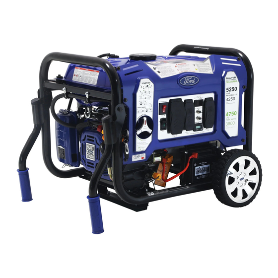
FEATURES A - Fuel Selector Switch F - Hour Meter G - 120 V duplex Receptacle (NEMA 5-20R). B - Main Circuit Breaker H - 120 Volt AC, 30 Amp RV receptacle (TT-30). C - Circuit Protector I - START/ON/OFF Switch D - Voltage Selector Switch E - 120 / 240 Volt AC, 30 Amp twist lock receptacle (NEMA L14-30). - Page 8 FEATURES Q - Support Leg (Foot) J - Fuel Gauge R - Fuel Tank K - Fuel Tank Vapor Vent S - Fuel Fill Cap L - Generator Frame T - Fuel Valve (ON/OFF) M - Choke Lever U - Recoil Starter Grip N - Air Filter V - Oil Fill (Dipstick) O - Handles &...
-
Page 9: Assembly
ASSEMBLY Unpacking 1. Place box on a level surface. 2. Remove all items from box except the generator. Make sure all items listed on the packing list are included and not damaged. 3. Cut down the sides of the box being careful to avoid hitting the generator. 4. -
Page 10: Remove Shipping Bracket
ASSEMBLY Remove Shipping Bracket (See fig 1) • Remove and discard the two RED shipping brackets and mounting hardware before starting the Generator. Attaching Wheels (See fig 2) • Parts needed - 2 wheels, 2 axles, 2 hair pins, 2 washers, 2 hub caps and 2 self-tapping screws. •... -
Page 11: Installing The Handles
ASSEMBLY Installing The Handles (See fig 4) Fig 4 Fig 5 Adding / Checking Engine Oil (See fig 6) • Place generator on a level surface. • Remove the crankcase dipstick to ensure you do not overfill the engine. • Insert a funnel into the crankcase dipstick hold and carefully add 4-Cycle engine oil (SAE10W- 30) to empty reservoir until oil reaches the outer edge of the oil fill hole (crankcase dipstick hole). -
Page 12: Connecting Generator To An Electrical System
OPERATION Fig 6 Fig 7 Connecting Generator to an Electrical System • If connecting generator to a building’s electrical system for standby power, you must use a qualified electrician to install a transfer switch. The power from the generator must be isolated from the circuit breaker or alternative power source. The connection must comply with all electrical codes and applicable laws. -
Page 13: How To Start Engine
OPERATION WARNING! Generator must be properly grounded to prevent electrocution. • Only operate generator on a level surface. • Always connect the nut and ground terminal on the frame to an appropriate ground source. How to Start Engine (See fig 9-16) Place generator on a level surface. -
Page 14: How To Stop Engine
OPERATION Never start or stop engine with electrical devices plugged in to the receptacles. Failure to WARNING! do so could damage the generator and / or connected electrical devices. • Always start the engine and let it stabilize before connecting any electronic devices. •... - Page 15 OPERATION 120 / 240 Volt AC, 30 Amp locking receptacle (L14-30R) • This receptacle has a 15A main circuit breaker to protect against overload. • This receptacle is rated to operate 120 Volt, AC, single phase, 60Hz loads requiring up to 3600 watts (3.6 kW) at 30 Amps.
-
Page 16: Don't Overload Generator
OPERATION Don’t Overload Generator Make sure you can supply enough rated watts and surge watts for all electronic devices connected to the generator. Rated watts refer to the power a generator must supply to keep a device running. Surge watts refer to the power a generator must supply to start an electronic device. -
Page 17: Cold Weather Operation
OPERATION Never exceed generator’s wattage / amperage capacity. This could damage the generator WARNING! and / or connected electrical devices. Check operating voltage and frequency requirements of all electrical devices prior to plugging them into the generator. • Hour Meter (See Fig 20) The digital hour meter operates whenever the engine is running and keeps track of how many hours the unit has been used. -
Page 18: Maintenance
MAINTENANCE Creating a Temporary Cold Weather Shelter In an emergency, the original shipping carton can be used as a temporary shelter. The shelter should hold enough heat created by the generator to prevent icing. Cut off all flaps. Cut off one of the long sides of the carton to expose the units muffler and exhaust. Do not enclose the muffler / exhaust side of the generator. -
Page 19: Changing Oil
MAINTENANCE Changing Oil (See Fig 21) • Run the Generator until the Engine is warm. • Place generator on a level surface. • Remove the crankcase dipstick. • Place an oil pan underneath the oil drainage bolt to collect used oil. Oil Fill &... - Page 20 MAINTENANCE Used oil should be disposed of at an approved disposal site. See your local oil retailer for CAUTION! more information. Air Filter (See Fig 22) A dirty air filter will reduce the life span of the engine, make it difficult to start the engine, and reduce the unit’s performance. •...
- Page 21 MAINTENANCE Carburetor Adjustment The carburetor is low emission and is equipped with a non-adjustable idle mixture valve. If adjustment is needed contact an authorized dealer. Replacing Fuel Filter (See Fig 25) Occasionally the fuel filter may become clogged and need replacing. To purchase a replacement fuel filter contact PULSAR customer service or your local small Engine repair shop.
- Page 22 MAINTENANCE Draining the carburetor • Turn the engine OFF. • Turn the fuel valve to the OFF position. • Position a suitable container under the carburetor drain screw to catch fuel; loosen the screw. • Allow fuel to drain completely into container. •...
-
Page 23: Troubleshooting
TROUBLESHOOTING Problem Cause Solution Engine is running, but AC output is not 1. Open circuit breaker 1. Reset circuit breaker available 2. Poor connection 2. Check and repair 3. Defective cord set 3. Check and repair 4. Connected device is faulty 4. -
Page 24: Diagrams
DIAGRAMS... -
Page 25: Warranty
From the date of original purchase, Ford Power Equipment warrants to the original purchaser that each portable generator sold, shall be free from defect in material and workmanship for the items and time period set forth below. Ford Power Equipment, at its discretion, agrees to repair or replace any defective part that upon examination, inspection, and testing by a Ford Power Equipment authorized service dealer, is found to be defective within the original warranty period. - Page 26 Take the original receipt and product to the place of purchase or mail the original receipt and product to the address found on the web site if purchased on-line. You can also locate your nearest Ford Power Equipment dealer for service or warranty questions by calling toll free at 1-888-863-7589.
- Page 27 MODELO: FG5250PBE Artículo: F2E425E991 Generador Manual del Operador ADVERTENCIA: El escape del motor de este producto contiene sustancias químicas que el estado de California causan cáncer, defectos congénitos u otros daños reproductivos. Producto Con Licencia Oficial www.fordpower.cc...
- Page 28 TABLA DE CONTENIDOS Introducción.....................................3 Especificaciones del Producto ............................3 Pedido de Piezas / Servicio al Cliente ........................3 Reglas de Seguridad ................................4 Símbolos de Seguridad ..............................4 Instrucciones de Seguridad ............................4 Características..................................7 Asamblea ....................................9 Desembalaje ................................9 Lista de Embalaje .
-
Page 29: Introducción
INTRODUCCIÓN Gracias por comprar este generador portátil de calidad superior de Ford Power Equipment. Al operar y mantener este producto según las instrucciones de este manual, su generador le dará muchos años de servicio confiable. Especificaciones del Producto: Este generador es impulsado por el motor, campo eléctrico giratorio, y alternando (AC) generador portátil corriente Está... -
Page 30: Reglas De Seguridad
REGLAS DE SEGURIDAD Símbolos de Seguridad ADVERTENCIA Indica un riesgo potencial de lo que podría resultar en lesiones graves o la muerte. PRECAUCIÓN Indica un riesgo potencial de lo que podría resultar en daños a equipamento o la propiedad. Humos Tóxicos Riesgo de Incendio Riesgo de Explosión Riesgo de Descarga Eléctrica... - Page 31 REGLAS DE SEGURIDAD Nunca exceda capacidad de potencia / amperaje del generador. Esto podría dañar e ADVERTENCIA generador y los dispositivos eléctricos conectados. • Compruebe el voltaje de funcionamiento y los requisitos de frecuencia de todos los aparatos eléctricos antes de conectarlos al generador.
- Page 32 Nunca opere esta unidad si hay piezas rotas o faltan piezas y sólo utilizan repuestos de ADVERTENCIA Ford Power Equipment diseñado específicamente para esta unidad. • El tratamiento inadecuado de este generador puede dañar la unidad y acortar su vida útil.
-
Page 33: Características
CARACTERÍSTICAS A - Selector de Combustible F - Medidor de Horas G - Un Enchufe de 120 V GFCI B - Cortacircuitos Principal H - Enchufe de 120 V CA, 30 RV (TT-30). C - Cortacircuitos I - Botón para ON/OFF D - Selector de Voltaje E - Enchufe de 120 V/240V CA, 30 A Twist Lock... - Page 34 CARACTERÍSTICAS Q - Soporte del Pie J - Indicador de Combustible R - Depósito de Combustible K - Ventilación De Vapor S - Tapa de llenado de combustible L - Marco del generador T - Válvula de Combustible (ON/OFF) M - Palanca De Estrangulación U - Arranque Manual N - Filtro de Aire V - Varilla y Entrada del Aceite...
-
Page 35: Asamblea
ASAMBLEA Desembalaje 1. Coloque la caja sobre una superficie plana. 2. Saque todos los artículos de la caja excepto el generador. Asegúrese de que todos los artículos que figuran en la lista de empaque están incluidos y no dañados. 3. Corte los lados de la caja con cuidado para evitar golpear el generador. 4. - Page 36 ASAMBLEA Retire Soporte (vea fig. 1) • Retire y deseche el soporte ROJO de transporte y accesorios de soporte antes de iniciar el Generador. Colocación de las Ruedas (vea fig. 2) • Piezas que se necesitan - 2 Ruedas, 2 Ejes, 2 pasadores de pelo, 2 Tapacubos y 2 Tornillos de rosca. •...
-
Page 37: Instalación De Las Manijas
ASAMBLEA Instalación de las Manijas (v fig 4) Fig 4 Fig 5 Agregando/Chequeado el aceite del motor (vea fig. 6) • Coloque el generador sobre una superficie nivelada. • Retire la varilla del cárter para asegurarse de que no desborde el motor. •... -
Page 38: Conectando El Generador A Un Sistema Eléctrico
ASAMBLEA Fig 6 Fig 7 Conectando el Generador a un Sistema Eléctrico • Si se conecta el generador al sistema eléctrico de un edificio para energía de reserva, debe utilizar un electricista calificado para instalar un interruptor de transferencia. La energía de el generador debe ser aislado de la interruptor de circuito o fuente de energía alternativa. - Page 39 OPERATION ADVERTENCIA Generador debe estar bien colocado adecuadamente para evitar electrocución. • Opere el generador en una superficie plana. • Siempre conecte la tuerca y el terminal de tierra en el marco de una fuente de tierra apropiado. Cómo arrancar el motor (vea fig 9-16) •...
-
Page 40: Funcionamiento
FUNCIONAMIENTO Nunca arranque o detenga el motor con los dispositivos eléctricos conectados a los ADVERTENCIA receptáculos. No hacerlo, podría dañar el generador y los dispositivos eléctricos conectados. • Siempre arranque el motor y dejar que se estabilice antes de conectar cualquier dispositivo electrónico. •... - Page 41 OPERATION 240 Voltios, 30 Amperios receptáculo de bloqueo • Este receptáculo tiene un empuje de 30 amperios para restablecer el disyuntor de protección contra sobrecarga. • Este receptáculo está clasificado para funcionar 120 voltios, AC, monofásica de 60 Hz que requieren cargas de hasta 3600 vatios (3.6 kW) a 30 amperios.
- Page 42 FUNCIONAMIENTO No Sobrecargue el Generador Asegúrese de que puede suministrar suficiente potencia nominal y sobretensiones vatios para todos los dispositivos electrónicos conectados al generador. Vatios nominales se refieren al generador de energía que debe suministrar para mantener un dispositivo que ejecuta. Vatios de carga se refieren a la potencia de un generador debe suministrar para comenzar un dispositivos eléctricos.
- Page 43 FUNCIONAMIENTO Nunca exceda vatiaje / amperaje del generador. Esto podría dañar el generador y / o ADVERTENCIA dispositivos eléctricos conectados. • Compruebe la tensión de funcionamiento y los requisitos de frecuencia de todos los aparatos eléctricos antes de conectarlos al generador. Medidor de Hora (vea fig.
-
Page 44: Mantenimiento
MANTENIMIENTO Creando un Albergue de Clima Frio Temporal En caso de emergencia, el carton original de envio puede ser usado como un albergue temporal. El albergue debe tener suficiente calor creado por el generador para prevenir congelamiento. 1. Cortar todas las aletas. 2. - Page 45 MANTENIMIENTO Cambiar el aceite (vea fig. 21) • Corra el generador hasta que el motor este caliente. • Colocar el generador en una superficie plana. • Saque la barilla del cárter. • Ponga un recipinte de aceite de bajo del perno del drenaje de aceite. •...
- Page 46 MANTENIMIENTO El aceite usado debe desecharse en un vertedro aprobado. PRECAUCIÓN Consulte a su distribuidor local de petróleo para mas información. Filtro de Aire (vea fig. 22) Un filtro de aire sucio puede reducir la vida del motor, haciendo dificultosamente el prender el motor y reduce el funcionamiento de la unidad.
- Page 47 MANTENIMIENTO Adjustamiento del Carburador El carburador es bajo en emisión y esta equipado con una valvula de mezcla de ralenti no adjustable. Si necesita ajustarle contacte un distribuidor autorizado. Reemplasando el filtro de gas (vea fig. 25) Ocasionalmente el filtro de gas puede taparse y necesitar reemplaso. Para comprar un reemplasante de filtro de gas contacte el servicio al cliente de o su taller de reparaciones de motores local.
- Page 48 MANTENIMIENTO Drenando el Carburador • Apagar el motor • Voltear la valvula de gasolina a la posición OFF • Posicionar un contenedor adecuado abajo del tornillo de drenaje del carburador para agarra la gasolina; afloje el tornillo. • Deje que la gasolina se drene completamente en el contenedor. •...
- Page 49 SOLUCIÓN DE PROBLEMAS Problema Causa Solución El motor esta corriendo 1. Abre el cortacircuitos 1. Reajustar el cortacircuitos 2. Conexión pobre 2. Examine y Reparar pero la salida del aire 3. Juego de cables defectuosos 3. Examine y Reparar condicionado no esta 4.
-
Page 50: Diagramas
DIAGRAMA... -
Page 51: Garantía
Cualquier producto que sea dañado por abuso o mal uso no sera cubierto por esta garantia. • El consumidor es responsable por el costo de la transportación a un centro de servicio autorisado de Ford Power Equipment. A menos que se solicite lo contradio, el envio por tierra sera aplicado como parte de envio y el cliente pagara cualquier cargo adicional de envios urgentes. - Page 52 Donde la Garantia es Validad: Para la cobertura de la garantia, este producto tiene que ser comprador de un distribuidor autorizado de Ford Power Equipment y la garantia solo se extiende al comprador original en los Estados Unidos, Canada, México. Renovados, usados, demostraciones, o modelos de piso no son cubiertas por esta garantia.
Need help?
Do you have a question about the FG5250PBE and is the answer not in the manual?
Questions and answers