
Subscribe to Our Youtube Channel
Related Manuals for Ford FG6250P


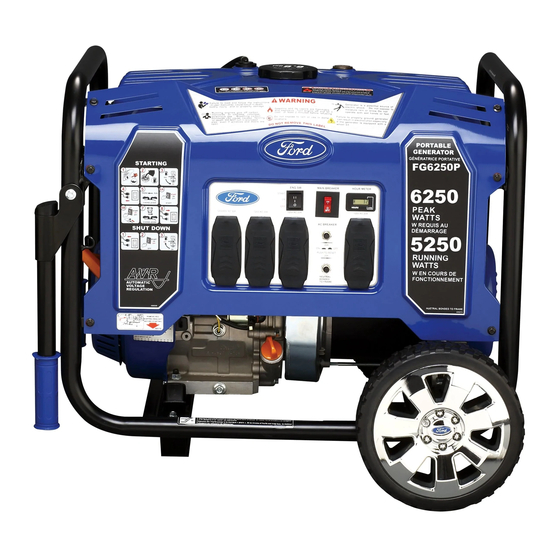
Summary of Contents for Ford FG6250P
- Page 1 FG6250P(E) - FG7750P(E) - FG9250P(E) Fig.A1 Copyright © 2016 P a g e www.fordpowerequipment.co.uk...
- Page 2 FG6250P(E) - FG7750P(E) - FG9250P(E) Fig. A2 Copyright © 2016 P a g e www.fordpowerequipment.co.uk...
-
Page 3: Table Of Contents
Installing Support Leg (See Fig.3) ............ 12 Attaching the Battery Cable (See Fig.4) ..........12 Installing the handles (Fig.5) ............13 Recoil starting (Fig.6)( FG6250P - FG7750P - FG9250P) ....13 BEFORE STARTING............14 Adding / Checking Engine Oil (See Fig.7) ......... 15 Adding Fuel (See Fig.8) .............. - Page 4 FG6250P(E) - FG7750P(E) - FG9250P(E) TO BALANCE THE LOAD ............. 20 CREATING A TEMPORARY COLD WEATHER SHELTER ..20 PRE-OPERATION STEPS ............ 20 AFTER EACH USE ............... 20 MAINTENANCE SCHEDULE ..........21 CHANGING OIL (SEE FIG.19) ..........21 OIL RECOMMENDATIONS ..........22 AIR FILTER (SEE FIG.20) ..........
- Page 5 FG6250P(E) - FG7750P(E) - FG9250P(E) 35.2 Maintenance ........Fout! Bladwijzer niet gedefinieerd. SERVICE ................30 Copyright © 2016 P a g e www.fordpowerequipment.co.uk...
-
Page 6: Application
FG6250PE - FG7750PE - FG9250PE – RECOIL/ELECTRIC STARTER Thank you for purchasing this superior quality portable generator from Ford Power Equipment. When operating and maintaining this product as instructed in this manual, your generator will give you many years of reliable service. -
Page 7: Package Content List
FG6250P(E) - FG7750P(E) - FG9250P(E) 3 PACKAGE CONTENT LIST Unpacking Place box on a level surface Remove all items from box except the generator. Make sure all items listed on the packing list are included and not damaged. -
Page 8: Safety Instructions
FG6250P(E) - FG7750P(E) - FG9250P(E) 5 SAFETY INSTRUCTIONS The manufacturer cannot anticipate every possible hazardous circumstance that the user may encounter. Therefore, the warnings in this manual, on tags, and on affixed decals are not all- inclusive. To avoid accidents, the user must understand and follow all manual instructions and use common sense. - Page 9 FG6250P(E) - FG7750P(E) - FG9250P(E) Tie back or wear protective head covering to contain long hair. WARNING! Keep engine away from flammable objects and other hazardous materials. The fuel and its vapors used to power this unit are highly flammable and could explode resulting in serious injury or death.
- Page 10 Never insert objects through cooling slots. WARNING! Never operate this unit if there are any broken or missing parts and only use Ford Power Equipment replacement parts specifically designed for this unit. Improper treatment of generator can damage the unit and shorten it’s life.
-
Page 11: Assembly (Fg6250P(E),7750P(E),Fg9250P(E))
FG6250P(E) - FG7750P(E) - FG9250P(E) 6 ASSEMBLY (FG6250P(E),7750P(E),FG9250P(E)) 6.1 Remove Shipping Bracket (See Fig.1) Remove and discard the RED shipping bracket and mounting hardware before starting the Generator. 6.2 Attaching Wheels (See Fig.2) Parts needed - 2 wheels, 2 axles, 2 hair pins, 2 washers, 2 hub caps and 2 self-tapping screws. -
Page 12: Installing Support Leg (See Fig.3)
FG6250P(E) - FG7750P(E) - FG9250P(E) 6.3 Installing Support Leg (See Fig.3) Parts needed - Support leg & M8 screw (2). Raise the front end of the generator high enough to gain access to the bottom of the frame. -
Page 13: Installing The Handles (Fig.5)
FG6250P(E) - FG7750P(E) - FG9250P(E) 6.5 Installing the handles (Fig.5) Fig. 5 6.6 Recoil starting (Fig.6 Attach the Recoil Starter Grip to the bracket. Fig.6 Copyright © 2016 P a g e | 13 www.fordpowerequipment.co.uk... -
Page 14: Before Starting
FG6250P(E) - FG7750P(E) - FG9250P(E) 7 BEFORE STARTING SULFURIC SHIELD EYES. NON-SPILLABLE ACID EXPLOSIVE FLUSH EYES •SPARKS SEALED BATTERY GASES CAN CAUSE IMMEDIATLEY •FLAMES CAUSE BLINDNESS This ready filled, WITH WATER BLINDNESS OR SEVERE •SMOKING activated sealed battery. INJURY BURNS Never remove strip. -
Page 15: Adding / Checking Engine Oil (See Fig.7)
FG6250P(E) - FG7750P(E) - FG9250P(E) 7.1 Adding / Checking Engine Oil (See Fig.7) Place generator on a level surface. Remove the crankcase dipstick to ensure you do not overfill the engine. Insert a funnel into the crankcase dipstick... -
Page 16: Operating Instructions
FG6250P(E) - FG7750P(E) - FG9250P(E) Never plug electronic devices into generator having frayed, worn, or bare wires. Never touch bare wires or make contact with receptacles. Never permit a child or unqualified person to operate generator. Keep children a minimum of 10 feet away from the generator at all times. - Page 17 FG6250P(E) - FG7750P(E) - FG9250P(E) WARNING! Pull cord recoils rapidly and pulls arm towards engine faster than you can let go which could result in injury. To avoid recoil, pull starter cord slowly until resistance is felt, then pull rapidly.
-
Page 18: Battery Charger For Electric Starter (For Fg6250P(E)
FG6250P(E) - FG7750P(E) - FG9250P(E) 8.3 Battery Charger for Electric Starter (FOR FG6250PE - FG7750PE - FG9250PE only) Keep the generator battery fully charged and ready to use to avoid the need to use the recoil starter to start the generator manually. -
Page 19: Vft Meter (Vft = Volts - Frequency - Time ) (See Fig.18)
FG6250P(E) - FG7750P(E) - FG9250P(E) within a +/- 10% voltage variation, and +/- 3 Hz frequency variation from the generator name plate ratings. To reduce the risk of damage, always have an additional load plugged into the generator if solid state equipment (such as television set) is used. A power line conditioner is recommended for some solid state applications. -
Page 20: Cold Weather Operation
14 TO BALANCE THE LOAD To obtain the best output and performance of your Ford Generator it is best to make every effort to balance the load on the outlets. Attempt to spread the load as evenly as possible by utilizing all outlets and try to run higher wattage device on separate outlets when possible. -
Page 21: Maintenance Schedule
FG6250P(E) - FG7750P(E) - FG9250P(E) 18 MAINTENANCE SCHEDULE After First 5 Hours Change Oil After 8 Hours or Daily Clean Debris Check Engine Oil Level Annually (25 hr Use) Check and Clean Air Cleaner Change Engine Oil (Service more often under dirty or dusty conditions) -
Page 22: Oil Recommendations
FG6250P(E) - FG7750P(E) - FG9250P(E) 20 OIL RECOMMENDATIONS Do not use special additives. Outdoor temperatures determine the proper oil viscosity for the engine. Use the chart to select the best viscosity for the outdoor temperature range expected. Note: Below 40°F (4°C) the use of SAE 30 will result in hard starting. -
Page 23: Air Filter (See Fig.20)
FG6250P(E) - FG7750P(E) - FG9250P(E) 21 AIR FILTER (SEE FIG.20) A dirty air filter will reduce the life span of the engine, make it difficult to start the engine, and reduce the unit’s performance. To clean, remove the air filter cover. -
Page 24: Replacing Fuel Filter (See Fig.23)
FG6250P(E) - FG7750P(E) - FG9250P(E) 26 REPLACING FUEL FILTER (SEE FIG.23) Occasionally the fuel filter may become clogged and need replacing. To purchase a replacement fuel filter contact your supplier (see manual back) or your local small Engine repair shop. -
Page 25: Draining The Carburetor
FG6250P(E) - FG7750P(E) - FG9250P(E) 27.2 Draining the carburetor Turn the engine OFF. Turn the fuel valve to the OFF position. Position a suitable container under the carburetor drain screw to catch fuel; loosen the screw. Allow fuel to drain completely into container. -
Page 26: Technical Data
FG6250P(E) - FG7750P(E) - FG9250P(E) 30 TECHNICAL DATA MODEL FG6250P(E) FG7750P(E) FG9250P(E) AC Output Frequency 50Hz 50Hz 50Hz Rated power 4000W 5000W 6000W Peak power 5500W 6500W 7500W Voltage 110V / 230-240V AC Engine 420cc OHV, 4 Stroke, Air Cooled... -
Page 27: Troubleshooting
FG6250P(E) - FG7750P(E) - FG9250P(E) 32 TROUBLESHOOTING Problem Cause Solution Engine is running, but AC Open circuit breaker Reset circuit breaker output is not available Poor connection Check and repair Defective cord set Check and repair Connected device is faulty... -
Page 28: Electrical Diagram (Recoil Starter Type)
FG6250P(E) - FG7750P(E) - FG9250P(E) 33 ELECTRICAL DIAGRAM (RECOIL STARTER TYPE) Copyright © 2016 P a g e | 28 www.fordpowerequipment.co.uk... -
Page 29: Electrical Diagram (Electric Start Type)
FG6250P(E) - FG7750P(E) - FG9250P(E) 34 ELECTRICAL DIAGRAM (ELECTRIC START TYPE) Copyright © 2016 P a g e | 29 www.fordpowerequipment.co.uk... - Page 30 FG6250P(E) - FG7750P(E) - FG9250P(E) 35 SERVICE How to contact us: To order parts, receive warranty assistance, or other services inquiries, you can contact us by : Please see contact data on the back of this manual. Record the following information bellow for service or warranty assistance...
Need help?
Do you have a question about the FG6250P and is the answer not in the manual?
Questions and answers