
Subscribe to Our Youtube Channel
Related Manuals for Ford FG7750


Summary of Contents for Ford FG7750
- Page 1 MODEL#: FG7750(E) FG(T)9250(E) FG(T)11050(E) Gasoline (Petrol) Generator OPERATOR’S MANUAL ORIGINAL INSTRUCTIONS LICENCED BY: PULSAR PRODUCTS INC 2051 S Lynx Place, Ontario, California, U.S.A 91761...
-
Page 2: Table Of Contents
TABLE OF CONTENTS Introduction..................................... 3 Product Specifications..............................3 Safety Rules.................................... 4 Safety Symbols................................4 Safety Instructions ..............................4 Features....................................7 Assembly....................................11 Unpacking ...................................11 Packing List ................................11 Attaching Wheels............................... 14 Attaching Battery Cable............................. 15 Adding / Checking Engine Oil............................15 Adding Fuel. -
Page 3: Introduction
INTRODUCTION Thank you for purchasing this superior quality portable generator from Ford Power Equipment. When operating and maintaining this product as instructed in this manual, your generator will give you many years of reliable service. Product Specifications: This generator is an engine-driven, revolving field, alternating current (AC) portable generator. It is designed to supply electrical power to operate tools, appliances, camping equipment, lighting, or serve as a back up power source during power outages. -
Page 4: Safety Rules
SAFETY RULES Safety Symbols Indicates a potentially hazardous situation which could result in serious injury or death if not avoided. Indicates a potentially hazardous situation which could result in damage to equipment or property. Injury of damage Read manual before use Wear noise protection Toxic fumes Risk of fire... - Page 5 SAFETY RULES Engine exhaust contains chemicals that lead to cause cancer and birth defects. • Always wash hands after handling generator. To reduce the risk of serious injury, avoid attempting to lift the generator alone. Never exceed generator’s wattage / amperage capacity. This could damage the generator and / or connected electrical devices.
- Page 6 Never transport or make adjustments to this unit while it is running. • Never insert objects through cooling slots. Never operate this unit if there are any broken or missing parts and only use Ford Power Equipment replacement parts specifically designed for this unit. •...
-
Page 7: Features
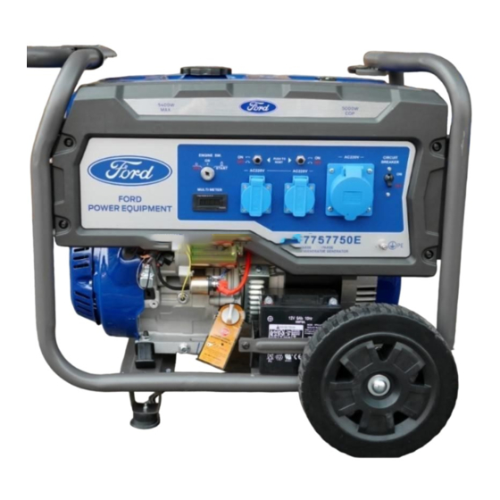
FEATURES A - Circuit Protectors (UK without) E - Grounding Stud (UK without) B - ON/OFF/Start Switch F - Outlets C - VFT Meter (Voltage, Frequency, Time/hours) D - Main Circuit Breaker... - Page 8 FEATURES - UK B - ON/OFF/Start Switch E - Grounding Stud (UK without) C - VFT Meter (Voltage, Frequency, Time/hours) F - Outlets D - Main Circuit Breaker...
- Page 9 FEATURES - THREE PHASE B - ON/OFF/Start Switch E - Grounding Stud (UK without) C - VFT Meter (Voltage, Frequency, Time/hours) F - Outlets D - Main Circuit Breaker...
- Page 10 FEATURES G - Fuel Gauge M - Fuel Tank N - Fuel Fill Cap H - Generator Frame O - Fuel Valve (ON/OFF) I - Air Filter P - Recoil Starter Grip J- Handles & Grips Q - Oil Fill (Dipstick) K - Oil Drain Plug R - Battery (Where Applicable) L - Support Leg (Foot)
-
Page 11: Assembly
ASSEMBLY Unpacking 1. Place box on a level surface. 2. Remove all items from box except the generator. Make sure all items listed on the packing list are included and not damaged. 3. Cut down the sides of the box being careful to avoid hitting the generator. 4. - Page 12 ASSEMBLY Universal Pattern Guide for AC Power Plugs/Sockets Electrical plugs and their sokets differ by country in shape, size, and type of connectors. The current worldwide plug/ socket pattern types are shown below-- categorized alphabetically by country or region. Country/Region Country/Region Voltage Voltage...
- Page 13 ASSEMBLY Universal Pattern Guide for AC Power Plugs/Sockets Country/Region Country/Region Voltage Voltage Pattern type Pattern type Country/Region Country/Region Voltage Voltage Pattern type Pattern type Country/Region Country/Region Voltage Voltage Pattern type Pattern type Okinawa Jamaica Uganda Japan 50/60 Oman Ukraine Jordan B,C,D,F,G,J United Arab Emirates C,D,G...
-
Page 14: Attaching Wheels
ASSEMBLY Remove Shipping Bracket (See fig 1) • Remove and discard the two RED shipping bracket and mounting hardware before starting the Generator. Attaching Wheels (See fig 2) • Parts needed - 2 wheels, 2 axles, 2 hair pins, 2 washers, 2 hub caps and 2 self-tapping screws. •... -
Page 15: Attaching Battery Cable
ASSEMBLY Attaching Battery Cable (See fig 4) • Parts needed - Black and Red battery cable • The Red (+) Connector should be attached to the battery first. • Remove the screw from the battery terminal. • Place the screw through the eyelet and tighten the screw and make sure the terminal will not touch any part of the frame. •... -
Page 16: Adding Fuel
ASSEMBLY Fig 5 Fig 6 Adding Fuel (See fig 6) • Set generator on a clean and level surface in an area that is well ventilated. • Remove fuel cap. • Insert a funnel into the fuel tank and carefully pour gasoline into the tank until fuel level reaches 1 ½ inches below the top of the neck. -
Page 17: Operation
OPERATION Grounding the Generator (See fig 7) The ground terminal located on the back of the generator frame must always be used to connect generator to a driven ground rod. Connect the ground terminal to the driven ground rod with a No 8 AWG (American Wire Gauge) copper wire. The wire connects to the terminal between the lock washer and nut. - Page 18 OPERATION Pulling direction Start handle Switch handle is in Switch handle is in run position Start position Fig 8 Fig 9 Fig 10 CHOKE CHOKE LEVER Fig 11 Fig 12 WAIT 5sec CHOKE CHOKE LEVER Fig 13 Fig 14 Never start or stop engine with electrical devices plugged in to the receptacles. Failure to WARNING! do so could damage the generator and / or connected electrical devices.
-
Page 19: Battery Charger For Electric Starter
OPERATION Battery Charger for Electric Starter Keep the generator battery fully charged and ready to use to avoid the need to use the recoil starter to start the generator manually. How to Stop Engine (See fig 15-18) All loads MUST be disconnected from the generator. Never start or stop the engine with electrical devices plugged in •... -
Page 20: Receptacles And Extension Cords
OPERATION • After moving the generator set, place the handle on the handle support block, as shown in the figure on the right, to ensure that the handle pins are locked. Then run the generator set. In storing and transporting the generator set, it is also necessary to put the handle back on the handle support block. -
Page 21: Don't Overload Generator
OPERATION Moving the Generator • Disconnect any electronic devices from generator then turn generator off. • Turn fuel valve to the “OFF” position. • Tilt generator until it balances on wheels. Roll machine to desired location. • If the generator must be carried, fold handle to the down position. Never lift or carry generator by its handle. This product is heavy and requires several people to lift. -
Page 22: Wattage Reference Guide
OPERATION Wattage Reference Guide (Wattages listed are just approximations. Check electronic device for actual wattage) Essentials Rated Watts Surge Watts Bathroom Rated Watts Surge Watts 75W Light Bulbs 75 each 75 each Hair Dryer 1250 18 CU Ft Refrigerator / Freezer 2200 Curling Iron 1500... -
Page 23: Cold Weather Operation
To Balance the Load To obtain the best output and performance of your Ford Generator it is best to make every effort to balance the load on the outlets. Attempt to spread the load as evenly as possible by utilizing all outlets and try to run higher wattage device on separate outlets when possible. -
Page 24: Maintenance
MAINTENANCE Creating a Temporary Cold Weather Shelter In an emergency, the original shipping carton can be used as a temporary shelter. The shelter should hold enough heat created by the generator to prevent icing. Cut off all flaps. Cut off one of the long sides of the carton to expose the units muffler and exhaust. Do not enclose the muffler / exhaust side of the generator. -
Page 25: Changing Oil
MAINTENANCE Changing Oil (See Fig 19) • Run the Generator until the Engine is warm. • Place generator on a level surface. • Remove the crankcase dipstick. • Place an oil pan underneath the oil drainage bolt to collect used oil. Oil Fill &... - Page 26 MAINTENANCE Used oil should be disposed of at an approved disposal site. See your local oil retailer for more information. Air Filter (See Fig 20) A dirty air filter will reduce the life span of the engine, make it difficult to start the engine, and reduce the unit’s performance. •...
- Page 27 MAINTENANCE Carburetor Adjustment The carburetor is low emission and is equipped with a non-adjustable idle mixture valve. If adjustment is needed contact an authorized dealer. Replacing Fuel Filter (See Fig 23) Occasionally the fuel filter may become clogged and need replacing. To purchase a replacement fuel filter contact the customer service or your local small Engine repair shop.
-
Page 28: Storage And Transportation Of The Generator
MAINTENANCE Draining the carburetor • Turn the engine OFF. • Turn the fuel valve to the OFF position. • Position a suitable container under the carburetor drain screw to catch fuel; loosen the screw. • Allow fuel to drain completely into container. •... -
Page 29: Troubleshooting
TROUBLESHOOTING Problem Cause Solution Engine is running, but AC output is not 1. Open circuit breaker 1. Reset circuit breaker available 2. Poor connection 2. Check and repair 3. Defective cord set 3. Check and repair 4. Connected device is faulty 4. -
Page 30: Diagrams
DIAGRAMS DIAGRAMS FG7750/FG9250/FG11050... - Page 31 DIAGRAMS FG7750E/FG9250E/FG11050E DIAGRAMS-...
- Page 32 DIAGRAMS UK: RECOIL START TYPE...
- Page 33 DIAGRAMS UK: ELECTRIC START TYPE...
- Page 34 DIAGRAMS - THREE PHASE RECOIL START...
- Page 35 DIAGRAMS - THREE PHASE ELECTRIC START...
-
Page 36: Noise
This information, however, will enable the user of the machine to make a better evaluation of the hazard and risk. Measured according with ISO8528-10, ISO 3744 and Noise Directive 2000/14/EC. MODEL FG7750(E) FG9250(E) FG(T)11050(E) Emission sound pressure level at the operator’s operation (according with... -
Page 37: Service
SERVICE WARRANTY: Please see the separate sheet in accessories. CE DECLARATION: Please see the separate sheet in accessories. HOW TO CONTACT US: To order parts, receive warranty assistance, or other services inquiries, please see the warranty sheet. Record the following information bellow for service or warranty assistance. Date of Purchase: Model Number: Series Number:...
Need help?
Do you have a question about the FG7750 and is the answer not in the manual?
Questions and answers