Table of Contents
Advertisement
Quick Links
Advertisement
Table of Contents
Troubleshooting

Related Manuals for Enerpac XC2402M


Summary of Contents for Enerpac XC2402M
- Page 1 Operation and Maintenance Manual XC2 Series Cordless Hydraulic Pumps Models XC2402M and XC2404M Document Number: L4587 Document Revision: E Issue Date: January, 2024 Language: English To reduce the risk of injury, user must read and understand this document before use.
-
Page 2: Warranty
Enerpac for quality tools, services and solutions. For additional information, visit www.enerpac.com. WARRANTY Refer to the Enerpac Global Warranty document for terms and conditions of the product warranty. Such warranty information can be found at www.enerpac.com. NAMEPLATE Refer to the pump nameplate for the product model number, serial number and other applicable information. -
Page 3: Table Of Contents
CONTENTS PAGE SAFETY ..............................4 COMPLIANCE ............................6 PRODUCT DATA ............................7 FEATURES AND COMPONENTS ......................9 DESCRIPTION ............................10 BATTERY ..............................11 OPERATION ............................. 12 MAINTENANCE ............................15 CLEANING ............................... 19 10.0 STORAGE ..............................19 11.0 SAFE DISPOSAL PROCEDURE ......................19 12.0 FIRMWARE UPDATES .......................... -
Page 4: Safety
All hoses, fittings and couplers used force hydraulic tools is required prior to the operation of with the pump must be rated at 10,150 psi [700 bar] the pump. If training is needed, contact your local Enerpac minimum. distributor or authorized service center for information •... -
Page 5: Battery Operated Pump Safety Precautions
• Avoid situations where loads are not directly centered • Use the Enerpac XC2 Series pump only with the on the cylinder plunger. Off-center loads produce specified Enerpac 54 volt Li-Ion battery. Use of any considerable strain on cylinders and plungers. -
Page 6: Compliance
Other symbols may be informational only. Understand the meaning of each symbol before using the pump. Enerpac declares that the model XC2402M and XC2404M Selected symbols are shown in the following chart: cordless hydraulic pumps have been tested and conform... -
Page 7: Product Data
0.82 0.33 XC2404M 10,150 * Maximum system pressure is limited to approximately 10,400 -10,800 psi [717 - 744 bar] by an internal safety relief valve. 3.3 Performance Graphs XC2402M & XC2404M ( XC2402M & XC2404M ( odels MetriC odels iMperial... -
Page 8: Battery And Battery Charger
Pendant Extension Cord, 10 ft [3 m] CC010 XC2404M Shoulder Strap, XC2 Series Pumps SSTRP55 Note: Refer to Enerpac website or catalog for a complete description of available pump accessories. 3.7 External Dimensions Dimension Models XC2402M & XC2404M Item inch 11.7... -
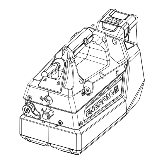
Page 9: Features And Components
17. Battery Charger 18. Remote Pendant Item may be included with pump or may need to be purchased sepa- rately. Refer to Enerpac website or catalog for ordering information. Optional Accessory Figure 1: Features & Components, Models XC2402M and XC2404M L4587_e... -
Page 10: Description
OFF ( O ) . Or, remove the battery Designed for use with double-acting hydraulic cylinders from the pump (if installed). and tools, pump models XC2402M and XC2404M feature a high-performance, brushless DC electric motor, two- Move the control valve lever several times back and stage hydraulic pump element and a manual 4-way, forth between the “A”... -
Page 11: Battery
Note: Hydraulic components are sold separately and are not included with the pump. Note: Shown in this graphic are various hydraulic components and devices typically recommended for Key: use with a double-acting cylinder or 1. Swivel Connector 5. Hose (advance) 8. -
Page 12: Operation
To ensure compatibility and proper operation, use by the pump’s built-in trigger or the optional remote only the specified Enerpac 54V Lithium-Ion battery with pendant. The trigger switch and pendant buttons are the pump. Refer to Section 3.5 for battery specifications non-functional when the power switch is in the OFF ( ... -
Page 13: Before Start-Up
Pump relief valve is factory set to approximately 10,150 psi [700 bar]. If a lower setting is desired, readjust the relief valve pressure as described in Section 8.5. 7.3 Operating Precautions WARNING Never allow any personnel to be under an object that is being supported only by the pump hydraulics. -
Page 14: Control Valve Operation
A - Advance N - Neutral B - Retract Figure 10: Control Valve Lever Positions 7.5 Control Valve Operation The pump’s manual control valve is operated by a rotary lever located at the front of the pump. See Figure 10 for valve positions. -
Page 15: Maintenance
Before moving or transporting the pump, be sure that the pump power switch is OFF ( O ) or that the battery is Use only Enerpac HF hydraulic oil when adding additional removed. This will help prevent accidental pump startup. -
Page 16: Adding Oil
Check oil for contamination by comparing the color of the and that the load is completely removed. oil in the reservoir fill tube to new unused Enerpac HF oil. Move the control valve lever back and forth between Unused Enerpac HF oil is a crisp blue color. - Page 17 11. Remove the oil fill plug and fill the reservoir with Turn off the pump power switch ( O ) . new Enerpac oil. Refer to Section 8.2 for hydraulic oil requirements and Section 8.3 for detailed oil fill Relieve any residual hydraulic pressure and instructions.
- Page 18 5/16 inch 7/32 inch Figure 15: Relief Valve Pressure Adjustment g. After adjusting the pressure setting, release the NOTICE Maximum system pressure limited trigger switch to stop the motor. approximately 10,400-10,800 psi [717 - 744 bar] by an internal safety relief valve. h.
-
Page 19: Cleaning
Do not spray water or cleaners inside the vents. The Enerpac Connect App is available for download on the Apple App Store and on Google Play. • Wipe the pump exterior with a dry, soft cloth. Avoid using strong detergents or cleaners. -
Page 20: Troubleshooting Guide
(pumps equipped with the pendant. optional remote pendant only) h. Motor and/or electronic Contact Enerpac authorized service center. control board damaged. i. Pump jammed due to Contact Enerpac authorized service center. obstruction. Possible internal damage to pump. - Page 21 Bypass valve malfunction. Contact Enerpac authorized service center. c. Oil intake screen clogged Contact Enerpac authorized service center. with debris. d. Control valve internal Contact Enerpac authorized service center.
- Page 22 Refer to procedure in Section 7.9. b. External hydraulic leak. Tighten connections. Replace damaged components. c. Control valve internal Contact Enerpac authorized service center. leakage, wear and/or damage. d. Pump element internal Contact Enerpac authorized service center. leakage, wear and/or damage.
-
Page 23: Repair Parts Section
14.0 REPAIR PARTS SECTION CONTENTS PAGE FIGURE 16: MAIN ASSEMBLY ......................... 24 FIGURE 17: SHROUD HALVES ........................26 FIGURE 18: RIGHT-HAND SHROUD COMPONENTS ..................28 FIGURE 19: PUMP BASE ASSEMBLY ......................30 FIGURE 20: POWER UNIT & RESERVOIR ASSEMBLY .................. 32 FIGURE 21: CONTROL VALVE &... - Page 24 Figure 16: Main Assembly 25A, 25C, 25D XC2402M Only Notes: Torque to 18-26 in-lbs [2-3 Nm]. Secure with Loctite 243 thread locking compound. Refer to manufacturer’s technical data sheet for application instructions. Be sure that valve is in the neutral (center) position before installing valve handle (item 5).
- Page 25 Parts List for Figure 16 Part Number Item Description Model XC2402M Model XC2404M Washer, Lock #10 B1086066 B1086066 Screw, SHCS Hex, M5 CBZ517028-1A CBZ517028-1A Handle, Valve Lever DD3398070 DD3398070 Pin, 6 mm x 45 mm Lg...
- Page 26 Figure 17: Shroud Halves Notes: Torque to 18-26 in-lbs [2-3 Nm]. Secure with Loctite 243 thread locking compound. Refer to manufacturer’s technical data sheet for application instructions. Torque to 25-30 in-lbs [2.8-3.4 Nm]. L4587_e...
- Page 27 Parts List for Figure 17 Part Number Item Description Model XC2402M Model XC2404M Plug, Soc Hd St Thread 0.750-16 B1006006 B1006006 Washer, Flat CAE1050108-1A CAE1050108-1A Screw, SHCS Hex, M5 CBZ517028-1A CBZ517028-1A Plug, Dome, 28 mm DD4112009 DD4112009 ...
- Page 28 Figure 18: Right-Hand Shroud Components Circuit App Board Connections Pendant Trigger Connector Cable Notes: Torque to 120-144 in-lb [13.6 - 16.3 Nm]. Torque to 60-80 in-lb [6.8 - 9.0 Nm]. Torque to 8-10 in-lb [0.9 - 1.1 Nm]. Secure with Loctite 271 thread locking compound. Refer to manufacturer’s technical data sheet for application instructions.
- Page 29 Parts List for Figure 18 Item Description Part Number Screw, M4 x 10 Thrd FRM DD3883028 Trigger, Variable Speed DD7874372 ✬ Shroud, Right-Hand DD7921424 Retainer, XC2 Oil Fill DD7926160 ✫ Circuit App Board DD7929827 Tube, Oil Vent DD7962268 ...
- Page 30 Figure 19: Pump Base Assembly Notes: Torque to 18-26 in-lb [2.0 - 3.0 Nm]. Torque to 10-12 in-lb [1.13 - 1.36 Nm]. Pull wires for switch through hole in housing. Pull wires through hole in housing. L4587_e...
- Page 31 Parts List for Figure 19 Item Description Part Number Screw, Flat Hd M5 CBA517028-1B Plate, Battery Interface w/Cable DD7953101 Bracket, Motor, XC2 DD8251111 Screw, M5 x 10, Thread Forming,Torx DD8781028 Base, XC2 Pump DD8836005 Switch, Rocker DPST 30 VDC 10A DD8866372SR Items included in 54V Battery Guide Kit, XC2BGK.
- Page 32 Figure 20: Power Unit & Reservoir Assembly Notes: Torque to 45-60 in-lbs [5.1 - 6.8 Nm]. Torque to 12-15 ft-lbs [16.3 - 20.3 Nm]. Secure with Loctite 2760 thread locking compound. Refer to manufacturer’s technical data sheet for application instructions. Install on eccentric housing (item 16).
- Page 33 Parts List for Figure 20 Part Number Item Description Model XC2402M Model XC2404M Ball Cap A8038570 A8038570 Spring, Compression A8126110 A8126110 Ball, 0.125, Stl B1003016 B1003016 O-Ring, Round, 0.219, 0.344, 0.063 B1004503 B1004503 ★ ★ ...
- Page 34 Figure 21: Control Valve & Miscellaneous Components View A Enlarged View Notes: Torque to 45-60 in-lbs [5.1 - 6.8 Nm]. Secure with Loctite 243 thread locking compound. Refer to manufacturer’s technical data sheet for application instructions. Lubricate seals before assembly. Apply PTFE tape.
- Page 35 Parts List for Figure 21 Item Description Part Number O-Ring, Round, 0.250, 0.375, 0.063 B1005503 ✾ ✤ O-Ring, Round, 0.219, 0.344, 0.063 B1009803 ✾ ✤ Back-Up Ring, Split, 0.250, 0.375, 0.045 B1010564 ★ ✾ ✤ O-Ring, Round, 0.938, 1.063, 0.063 B1227503 ✾...
- Page 36 Figure 22: Control Valve Assembly, 4-Way, 3-Position, Manual Orient Holes as Shown Note: Lubricate seals before assembly. L4587_e...
- Page 37 Parts List for Figure 22 Item Description Part Number O-Ring, Round, 0.156, 0.281, 0.063 B1002503 ✾ ✤ O-Ring, Round, 1.250, 1.438, 0.094 B1259503 ✾ ✤ Poppet DA11071041 ✾ ✤ Washer, Back-up DA7285566 ✾ ✤ Manifold, 4/3 Valve DD2997840 ✤ Spring, 0.25 OD, 0.172 ID DD4446110 ✾...
- Page 38 Figure 23: Control Valve Cover Assembly Sectional View (enlarged) Notes: Press fit into item 7. Press fit into item 11 when aligned with item 2. Secure with Loctite 243 thread locking compound. Refer to manufacturer’s technical data sheet for application instructions. Torque to 21-26 in-lbs [2.4 - 3.0 Nm].
- Page 39 Parts List for Figure 23 Item Description Part Number Ring, Round, 0.250, 0.375, 0.063 B1005503 ✾ ✤ Pin-Spring, 0.094, 0.750, Stl B1040057 ✤ Pin-Spring, 0.250, 0.625, Stl B1126057 ✤ Needle Bearing CB183155 ✾ ✤ Thrust Race CB184155 ✾ ✤ Plug and Disc Assembly DA7289900 ✤...
- Page 40 Figure 24: Eccentric Shaft & Housing Subassembly Notes: Position grey coated side of bushing (item 5) toward eccentric (item 3). Spin test after assembly (1 full eccentric rotation). Use a pick to align the gears with the ring gear. L4587_e...
- Page 41 Parts List for Figure 24 Item Description Part Number Ring Gear DC7089228 Bearing DC7096155 Assembly, Eccentric Shaft (See Figure 25) Key, Ring Gear DC7452251 Bushing DC7464108 Eccentric Housing DD8425001 Items included in Eccentric Housing Service Kit, XC2ECK. ...
- Page 42 Figure 25: Eccentric Shaft Assembly Sectional View Notes: Position grey coated side of thrust washer (item 4) toward lip seal (item 1). Figure 26: Pump Element L4587_e...
- Page 43 Parts List for Figure 25 Item Description Part Number Lip Seal DC7090476 Eccentric, 4mm DC7117537 Subassembly, Eccentric Shaft DC7870950 Washer, Thrust DC7186108 DC7191251 Spring, Wave DC7750410 Subassembly, Cam DC7755950 Items included in Eccentric Housing Service Kit, XC2ECK. ...
- Page 44 Figure 27: Pump Element Components 0.59 - 0.63 inch [15.0 - 15.9 mm] Notes: Torque to 9.6-11.8 ft-lb [13 - 16 Nm]. Torque to 44.3-52.3 ft-lb [60 - 71 Nm]. Torque to 18.5-22.1 ft-lb [25 - 30 Nm]. Adjust length of bypass end cap (item 18) to between 0.59-0.63 inch [15.0 - 15.9 mm] from spot face.
- Page 45 Parts List for Figure 27 Item Description Part Number Plug, Flush, Hex 27.0 Stl Teflon A1006245 ✦ Ball Cap A8038570 ✦ Spring, Compression A8126110 ✦ Ball, 0.125 Stl B1003016 ✦ Ball 0.188 Stl B1005016 ✦ Back Up Ring, Split B1006564 ★...
- Page 46 • Charger must be purchased separately if not included in the shipment with the battery or tool. Unit is auto-voltage sensing, 100-240 VAC, 50/60 Hz. • North America, Europe and Australia: Charger and power cord includes one Enerpac EC1F54 battery charger and the AC power cord for use in the selected region. Charger not sold without power cord.
- Page 47 Parts List for Figure 28 Item Description Part Number Battery, 54V, Lithium-Ion, 4.0 Ah, 216 Wh EBH544 Battery Charger & Power Cord, Australia - 230V EC1F542A Battery Charger & Power Cord, North America - 115V EC1F541B Battery Charger & Power Cord, European Union - 230V EC1F542E Power Cord, Japan - 100V ECC541N...
- Page 48 Figure 30: Hydraulic Schematic PUMP OUTLET PORTS 4-WAY, 3-POSITION DIRECTIONAL CONTROL VALVE CHECK VALVE USER-ADJUSTABLE RELIEF VALVE ELECTRIC MOTOR Note: Pump internal safety relief valve set at 10,400- 10,800 psi [717 - 744 bar]. PUMP OIL INTAKE FILTER HYDRAULIC RESERVOIR L4587_e...
- Page 49 Figure 31: Electrical Schematic L4587_e...
- Page 50 NOTES _______________________________________________________________________________________ _______________________________________________________________________________________ _______________________________________________________________________________________ _______________________________________________________________________________________ _______________________________________________________________________________________ _______________________________________________________________________________________ _______________________________________________________________________________________ _______________________________________________________________________________________ _______________________________________________________________________________________ _______________________________________________________________________________________ _______________________________________________________________________________________ _______________________________________________________________________________________ _______________________________________________________________________________________ _______________________________________________________________________________________ _______________________________________________________________________________________ _______________________________________________________________________________________ _______________________________________________________________________________________ _______________________________________________________________________________________ _______________________________________________________________________________________ _______________________________________________________________________________________ _______________________________________________________________________________________ _______________________________________________________________________________________ _______________________________________________________________________________________ L4587_e...
- Page 51 NOTES _______________________________________________________________________________________ _______________________________________________________________________________________ _______________________________________________________________________________________ _______________________________________________________________________________________ _______________________________________________________________________________________ _______________________________________________________________________________________ _______________________________________________________________________________________ _______________________________________________________________________________________ _______________________________________________________________________________________ _______________________________________________________________________________________ _______________________________________________________________________________________ _______________________________________________________________________________________ _______________________________________________________________________________________ _______________________________________________________________________________________ _______________________________________________________________________________________ _______________________________________________________________________________________ _______________________________________________________________________________________ _______________________________________________________________________________________ _______________________________________________________________________________________ _______________________________________________________________________________________ _______________________________________________________________________________________ _______________________________________________________________________________________ _______________________________________________________________________________________ L4587_e...
- Page 52 ENERPAC TOOL GROUP CORP N86 W12500 Westbrook Crossing Menomonee Falls, WI 53051, USA © 2023 Enerpac Tool Group, All Rights Reserved. www.enerpac.com...
Need help?
Do you have a question about the XC2402M and is the answer not in the manual?
Questions and answers